The "General Faves" have been updated with the new poche pen for all the model elements. If you are going to change poche pen color in a current project, and you use Favorites, you should load the new version.

Click the flyout on the favorites palette and choose "Load Favorites". Navigate to the favorites file you want. We keep general favorites at 3 Resources : Favorites.
If you already have favorites in the list, you will be asked if you want to Merge or Replace the existing favorites. Unfortunately, "Replace" refers to the list as a whole: All the current favorites will be deleted. To overwrite current favorites with those in the new file, while leaving the others alone, you need to choose "Merge." This has its own quirk: When a matching name is found, you will be offered the options "Skip" (don't overwrite), "Skip All" (which cancels all remaining overwrites), and "Overwrite". There is no "Overwrite All", so in order to accept all the incoming favorites, you have to click "Overwrite" however many times. Another D-minus interface element.
Also, I can't stand the word "favorites". It means I have a great subjective, emotional, aesthetic interest in the item, much greater than in most items. "OMG, I loooooove this 2x4 wall!!!" No. They should be called presets.
It will be a few minutes until I can update the relevant Workflow posts re the new plotter.
PLN:
Poche Pen: Instead of using a pen from the gray region, we have a dedicated poche pen. This should make changing the color of poche easier in the future, if we ever have to do it again. It's pen 50. All the model tool defaults and composites are updated. (This change is optional for current projects, but it is supported by the new layout book.)
Finish fill pen to 92 from 93. Default of fill tool changed accordingly, along with cover fill setting for cover fill elements.
Title block, drawing area, detail area, SK objects switched to new version. Drawing area and title block hotspots replaced.
New pen settings: Adjusted weights, and color of pen 50. Attribute file: Color Pens 0105.aat. PlotMaker Pens are in Black Pens 0105.aat.
Deleted stupid drawing area from Perspective View window.
LBK:
New pen settings: Adjusted weights, and color of pen 50.
Plot setup tiffs removed.
Changed page setup for each master layout.
Adjusted title block, sheet number text, and detail grid locations for each master.
Here's a new category where I'm going to log changes to the templates. It's not required reading, but if you're curious go ahead.
This is how to install our gigantic new plotter. Installing other printers is similar in some respects.
System Preferences, Print & Fax, Set Up Printers.
Click "Add".
At the top, select "IP Printing"
Printer Type: LPD/LPR
Printer Address: 192.168.1.29
Queue Name: WINPRINT (Case sensitive)
Printer Model: Other...
Navigate to 3 Resources : Printers : RW470 : RW-470.ppd
Choose.
Add.
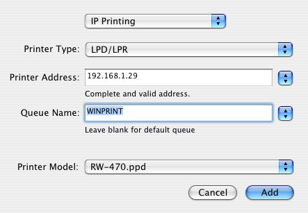
If the settings look like this, click Add.
The new printer should appear as "WINPRINT on 192.168.1.29". This is also the name you will see in Page Setup. It will be the default, unless you want to make another printer the default. (If so, select it and click "Make Default".)
Don't forget to do page setup in PlotMaker:
Go to File -> Page Setup. (Not Plot Setup!) At "Format For", select "WINPRINT 192.168.1.29". Select the Paper Size from the next pulldown. 18x24 is ARC C. 24x36 is ARC D. 30x42 is 30X42, not ARC E.
If you don't see 30X42, make sure you got the ppd file from the RW470 folder, nowhere else.
No, that's not all there is to it.
The camera makes it look fat
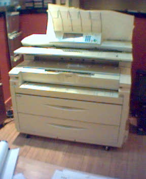
We have a new plotter. Actually it's a printer. Everybody calls it a plotter, though. Soon we won't plot anymore, we'll just print, like everyone else, and then we'll call printing on big sheets plotting, like everyone else, and we'll call the big new output device a plotter.
(You think I'm being technical and pedantic, but one of the main sources of trouble in getting this thing in here has been that there IS a difference, and the people selling us the, ah, machine think there isn't. It's also the cause of the hard labor you will have to do on each project to get your output looking as good as it did before.)
So we have a good news/bad news/bad news/good news situation.
The good news is that it works.
The bad news is the hard labor of adjusting our workflow.
The other bad news is the plotter requires a "PC" in order to function. A PC is sort of like a computer except it breaks a lot.
The other good news is the output is insanely fast (7 pages a minute). And, since they're forcing us to print, we will gain several appealing advantages of printing over plotting, such as easier publication, sharing, and archiving. I.e., PDFs. And it scans large sheets, so we can electronically archive Jim's basement, including the hand-drawn stuff. Wild!
Here's a summary of the changes to our lives:
� Plotting is going away, including Plot Setup, PlotFlow, and the Plot command. We will print instead.
� We won't send drawings out as often. We can print a 35-page set in 5 minutes! Twenty 35-page sets, we'll still send that out.
� You have some work to do on current projects to get them looking good. This is a big change and it just isn't magic.
� We will archive using PDF instead of PLT files. We can scan old paper sets to archive them to PDF.
Thank you for your patience as we work out the remaining kinks.
By the way, up to this point I have been trying to get our plotting ability back on line, so I'm not an expert in scanning and copying yet, let alone changing the toner and whatnot. One thing at a time.
Several related posts:
Installation
New Title Block
Project Changes
Layout Book Changes
This is an unpleasant task you should never have to do, unless we get a new plotter. You don't even have to do it then.
On the Options menu, All Pens And Colors. You get this:
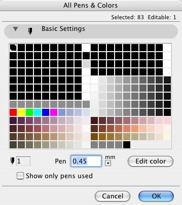
A pen has two attributes, color and width.
Set the width using the field marked "Pen". Make sure the units are mm, not Pt (points).
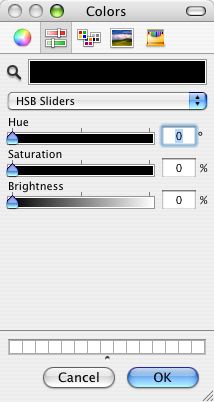
To change the color, double-click the pen's square in the grid, or select it and click "Edit Color". I recommend using the HSB sliders to edit color.
You can select multiple pens at once and edit their color or width together. Cmd+click on pens to accumulate them, or Shift+click to select a range. Like a lot of things.
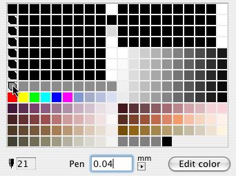
Selecting all the pens between 21 and 141.
Editing pens in Archicad is similar, but we can use Attribute Manager instead.
Since we got a new plotter, we need a new title block. Makes sense to me.
Before printing from the new plotter, you must switch to this title block object. When switching, hold down command and option and click on the new object. This is very important so you don't lose your old issue dates. If you try switching and it doesn't work, cancel out of the object settings and try again.
The object looks the same, but I took the opportunity to fix/add a couple things.
The overall size of the object, including the margins, is the same as the paper in the layout. In the previous version, the size matched the printable area. When changing an existing project, make sure the lower left corner of the title block drawing is on the lower left corner of the paper. (The outermost rectangle, if you can see a difference, which for large sheets you won't.)
You can have up to eight dates instead of five. You can limit the number date spaces to four.
If the client name doesn't fit the title block horizontally, you can make the point size smaller (Custom Project Size), or put part of the name on a second line (More Project Name). Note: This parameter is separate from the Book Info. You can still use the Book Info for the other fields. That is, if you want the second line, you have to set it in Archicad.
I turned all the pens black, and lightened the gray on the square a little.
Location: 01 General / 1 Graphic Symbols
Just like Slope Symbol JAM8, except it's a label. Used as associated label on a roof, it will convert the slope to n/12 and draw the triangle correctly. This symbol is typically used in section and elevation, but I could see using it in the roof plan.
Select the roof you want to label and check 'Label Elements' in the Info Box.
(To set the label tool to use this label on roofs, go to the default settings of the label tool, highlight Roof Tool in the top panel, and select Roof Slope JAM9 from the flyout.)
After activating the label, you will have to move it into position. Make sure "Use Symbol Arrow" is checked in the Info Box. This keeps the leader from being drawn.
To label a roof which slopes in the other direction, switch the "Mirror" parameter to On. Conventional mirroring doesn't work.
You can stretch the length using the green node.
The hypotenuse is optional for outsiders. In our standards it is on.
See Also: Labels
You can drag and drop libraries to the Library Manager from the Finder.
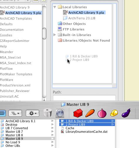
Like this
This is recommended for lots of issues, and it's at least partially voodoo. But it worked for me.
This is one of the stock OS X troubleshooting tips. It does actually solve some problems, and it doesn't do any harm.
Open the Disk Utility application in Applications : Utilities.
Select your hard disk name in the left panel. Select the First Aid tab in the right panel. Click the Repair Permissions button at the bottom.
It will take about 5 minutes, depending on the size of the disk. When the repair finishes, quit Disk Utility and restart the machine.
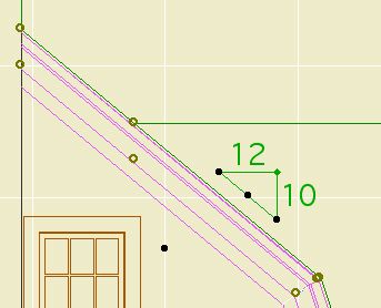
The label gives the height of a wall. It will typically be used for knee walls. It can be used in section or in plan. It will only work as an associated label; select the wall and check the "Label Elements" box.
The value displayed is the height of the wall in the settings. This means that for trimmed walls, you have to "Set wall height to highest point" when trimming, or manually set the wall height to an appropriate value. Tip: trim the wall using "highest point", then round the height UP to the next 1/4", 1/2", or whole inch.

See Also: Labels
Location - 13 Special Construction
From the Objects We Wouldn't Need If the Tools Worked Right...
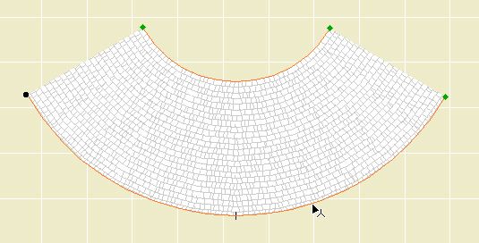
The object makes a roof curved around the Z axis. That is, it's not a vault. Here's three of the four that are in use on Vassos.
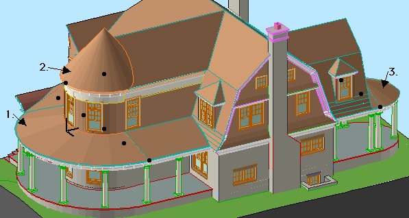
The point is: If you use roof elements, you get a lot of extra lines. With this object you don't. You will still get a line where the object meets a regular roof, but I can't do anything about that. Instead of 16 extra lines, you have two. We do what we can.
The outer radius is controlled by the length parameter. The inner radius, as shown on the porch roof above, is controlled by the "Inner Radius" parameter. If this is zero, you get a point, as shown on the tower.
Naturally you can set the slope and the thickness. Currently the bottom edge is always horizontal; place a slab under it. You can set the three materials separately, as with a conventional roof.
The edge of the roof is detectable in plan, and there are editing hotspots for the arc degrees and the two radii.
The object can show a fill in plan. The fill orients itself to the slope. The fill is a cover fill, so its display will follow the display of the conventional roof fills.
Location: 06 Wood & Plastic : Structure
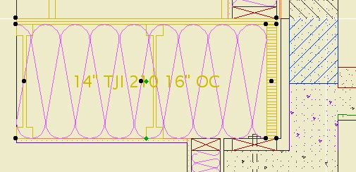
A 2D symbol for framing in section. It's been around a while, but I added a couple things.
Choose the member type (2x, TJI, LVL) and the spacing. The spacing can be customized.
In building sections (1/4" and 3/16" scales), the label or the joists themselves can be turned off. The label turns itself off when there's not enough room for it. The label can be dragged with in symbol. Turn the joists off when the section cut is parallel to the joists.
In wall sections (3/4" scale and larger), there are some more options. You can show TJIs sideways, which will show the top and bottom flange, along with the rim joist. For cut TJIs, you can choose to show the end joist as a rim joist or not. You can show sheathing on top of the joists. Finally, you can turn on the insulation symbol, so you don't have to draw the insulation separately.
L Wall2 and L Wall3 are for landscape walls.
L Wall2 shows in the floor plan, while L Wall3 does not. L Wall2 is hidden in the structure plans. We want to see landscape walls in the architectural plans for clarity, but we want to omit them from the framing plans if the aren't in the main contract/permit.
Location: 01 General / 6 Zone Stamps
This is a lot like the JAM8 zone stamp, which was a lot like the room name object.
You can select the room name and the floor finish. The font of the room name comes from the main settings of the stamp. The font of the material has its own setting.
One new feature is the option to show the room number along with, or instead of, the name. The number should generally be shown in the construction documents, in conjunction with the finish schedule. If the number is shown, the floor finish will not be.
The other new feature is the listing parameters for ceiling finish, crown, and baseboard for the finish schedule. These parameters are independent of elements placed in the room.
Since AC8, objects have had the ability to have nodes that edit parameters other than height and width. In GDL jargon, this functionality is called Graphical Editing. These nodes respond to the stretch command as well as the stretch button of the pet palette. Even though they can do things besides stretch.
Since AC8.1, editing nodes have been diamond-shaped instead of round, so you can tell them from the non-editing ones.
In AC9, they decided that wasn't clear enough, and now editing nodes can have a different color. (Options -> Preferences -> Miscellaneous) The default is green, and I haven't been motivated to change it. When you see a green, diamond-shaped node, try it and see what it does.
Editing a crown miter
While editing with one of these nodes, a palette pops with the name and value of the parameter(s) being edited. (Some nodes edit two parameters at once.) If you type "N", the value in the palette will highlight and you can enter the value directly, just like typing "R".
In Library Manager, the History tab shows the libraries that have been loaded recently (since the last Clear or Clear All). This list is independent of any particular project.
Typically we use the exact same libraries all the time. But there are exceptions; sometimes you need the version 7 library, for example. If you've loaded that library recently, you can add it from the history tab instead of scrolling through the whole Local/LAN tree.
It's also helpful if you take projects home. When you open a project in a different location, the library manager will come up because the servers aren't there and your local Archicad folder path is different. But the history tab remembers the local instances of the libraries, making it easy to load them quickly.
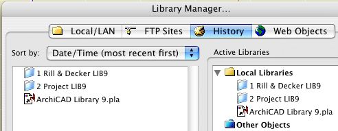
If you load a "wrong" library at some point, you can use the "Clear" button to delete it from the history so you're not tempted by it in the future.
This layer sort of "forks off" from the layer S Slab.
Use it for framed structural decks (TJIs, 2x12s, etc). Continue to use S Slab for concrete slabs.
Why? Because decks aren't slabs. Yes, they're both made with the slab tool, but layers represent project elements, not tools. As much as possible, layer names should represent real things.
Where does this leave the layers A Deck2 and A Deck3? Right where they were. Model the deck surface on A Deck3. Model the structure of a deck on S Deck. Place 2D elements representing the (architectural) deck on A Deck2.
Problem: When dragging roof handles, they would sometimes end up at an arbitrary point, rather than where they were dragged.
Other problem, which only emerged after reinstalling AC: Attempting to pan with the scroll wheel would zoom instead.
We tried everything*, including wiping the disk. The fresh system fixed the panning problem. We were bringing in the work environment when we discovered that the trouble was caused by the User Preference Schemes segment of the RND Profile. We re-exported the scheme to the Onion.
Fortunately, that scheme is easily rebuilt. If the shortcuts or the Info Box had been the problem, I would have been very sad.
Moral: If you see weird behavior in Archicad, try switching to a standard Work Environment profile. If that fixes it, recreate the needed profile and trash the old one, and don't reinstall your system!
* Unrotating the grid. Looking for pattern related to shift constraining. Trying different files, and new roofs. Trying to reproduce the problem on another machine. Checking permissions. Saving locally. Saving and reopening an archive. Trashing the prefs. Trashing the caches. Creating a new user and seeing if "he" has the problem. Reinstalling Archicad.
It's odd that neither trashing the prefs or creating a new user solved the issue, since the Work Environment is in the prefs. But we tested the cause carefully as we brought the WE back, and it's definitely the culprit, probably in combination with an underlying system problem.
UPDATE: The precise setting that caused the problem is the "Pet palette movement" under User Preference schemes -> Dialog boxes and palettes. "Follow Cursor" was the culprit. Switching to "Jump to preferred position" fixed it.
A particularly self-starting member of the Archicad community, Karl Ottenstein, has developed an add-on called QuickDisplay, which allows us to assign keyboard shortcuts to various display options. The commands are toggles, which means you can strike a key turn the Section Depth (e.g.) on, and then strike the same key to turn them off. He has generously allowed this add-on to be used free of charge. Here is the Archicad Talk topic where mad, righteous praise is heaped upon him.
Here is Karl's page with full instructions for the add-on. I will summarize the high points.
Get the file from 3 Resources : Add-Ons. Place it in your local Applications : Graphisoft : Archicad 9 : Add-Ons. Launch or relaunch Archicad.
Your Display menu should now have a QuickDisplay submenu at the end. Here you will see commands for toggling various display options.
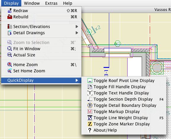
QuickDisplay Submenu
Naturally, and I hope obviously, you don't go to this menu to activate the commands. That wouldn't be much of a shortcut would it. The commands have to be on a menu in order to have shortcuts assigned to them.
As you can see, I only have shortcuts assigned to two of the commands, Section Depth and Line Weights, on F4 and F5 respectively. I toggle the others much less and I don't need a shortcut for them. You can do whatever you want.
I have updated the RND Keyboard scheme with these two shortcuts. You can import the updated scheme at Options -> Work Environment. The scheme is located at 3 Resources : Work Environment : RND Profile : Shortcuts.
For information on assigning shortcuts, see the Archicad Reference Guide, page 153, or ask for help.