On Land

Environment Information
At Rill Architects we run ArchiCAD on macOS. If you work at Rill, this is your stuff. If you don't, but you work in ArchiCAD, you may find something interesting. Anybody else, I don't know.
RSS
March 2005 Archive

All Entries | 1 | 2 | 3 | 4

I redrew the "Flagstone Random" fill pattern, in an attempt to get it to redraw faster in vectorial. I cut the number of lines by about 50%. There are now only 1700 lines in a 10' x 6' rectangle.

It's a little faster. Not as much as I expected, but every little bit yada yada.

If you want to try it, you can pull it from the Vassos project using Attribute Manager. Here's the before and after:


I think the new one looks better too.

If no one complains I will replace the fill in the templates in a little while.

Location: 03 Concrete

The main parameters are the height, width, and thickness.

By default, the overlap matches the thickness, and the tread is double the thickness. To change either value, set the parameters to other than zero.

The length of the object cannot be controlled. The idea is to let the object tell how much length is needed to step up the required height. The resulting length is the distance between the adjacent slabs. The length is shown, locked, in the length field.

The object "starts" at the bottom. When the length changes, the top end moves.

The top of the object will match the top elevation of the upper slab footing. The bottom, it depends:

If meeting the lower footing "in line", the bottom elevation should match the top of the lower slab, and the "Bottom Lap Segment" should be on. If meeting the lower slab at a "T", the bottom of the object should match the bottom of the slab, and the lap segment should be off. I think the second case is more typical, and is shown in the image below.

The "length" rectangle is shown with the floor plan pen of the object. The adjacent slabs should meet the ends of this rectangle. The red line indicates the bottom of the object, and the extent of the Bottom Lap Segment, if on. The light pink line shows the physical extent of the object at the top. Both these lines print white. The lines in between represent the elevation changes (steps).


In plan.

Placement: The object should be drawn with a dashed line. I suggest using a different pen from your footing slabs, with the same weight. Use the layer S Footing. Set the bottom elevation first, as described above. Next, set the top elevation. The object will extend to accommodate the needed "treads". Then adjust the upper slab to meet top end of the object. (This end is represented by two small lines instead of a full line, so it doesn't interfere with the end line of the slab.) Whenever you change any parameter of the object, you will need to adjust the top slab too.

Cutting the foundation wall: The wall which sits atop the object should extend to the edge of the top slab. The wall's base should be at the top of the lower footing. Subtract the object from the wall with downward extrusion. Without SEOs, this object wouldn't be possible.


Cutting the wall.

I was happily (!?!) putting in the rake mouldings for the gambrels on Vassos. On the sixth one, the outer rake failed to subtract from the steep roof of the gambrel. All the others had worked. Imagine my joy when I saw that all five previous subtractions at the same condition had also failed.

The "solution" is to slightly change the edge angle of the upper roof edge. In my case, the angle of the edge when mitered to the upper roof was 74.3651º. I rounded up to the nearest hundredth of a degree, to 74.3700º. To keep the section through the miter looking presentable, I had to change the adjacent edge angle of the upper roof.

Over time I have have seen these subtractions continue to deteriorate, and I have to change the angles again. It's a pain, but there is no other way to model complex rakes.

Update: This issue is greatly improved in 10 and in the later patches of 9.

A single building element, how about a window, will be represented multiple times in the construction documents.

There's the window in a plan, at least one elevation, often two or more sections, maybe/probably an interior elevation, maybe a wall section, and the window schedule. Then there are dimensions and annotations related to the window. Five to fifteen representations of one element is probably typical.

The goal is to generate these representations with as few project elements as possible. The ideal is one. With a one-to-one ratio of project elements to building elements, you can focus on manipulation of an element, knowing the representations will largely take care of themselves.

With multiple project elements per building element, it falls to you to maintain the integrity of each and every representation. You work more, do the same things over and over, have less fun, and make more mistakes, which, considering how hard you've been working, is a downer.

When you choose to draw a building element that could be modeled, you are shifting the responsibility for the representation of that element away from the software and onto yourself. When you unlink a section/elevation, you are signing on to change that one door or window multiple times. As multiple building elements change multiple times, the added work, and the risk of error, grows exponentially.

This ideal of of unity is only partially attainable with current technology. But you should have a good grasp of how attainable it is.

For example, full-height walls are relatively unified. They display well, automatically, in a wide variety of contexts. Low walls, however, are less unified: Since the plan and section fills can't differ, you need two elements, a wall and a slab, for the the plan and the section. (Update: In 10 this is somewhat improved. You can show a top view of a wall, but you can't control the fill.) (Update: In 20, you can use Graphic Overrides to put a background fill color on the top. No fill pattern, just the background, but still an improvement.)

The reflected ceiling plan is a great divider. Many elements need to be drawn over. Beams, dashed in plan, need to drawn solid, while floor elements, solid in plan, need to be drawn dashed. Given the current design of the software, we're stuck with this. Update: Graphic Overrides changed everything.

A lot a higher-level object design is concerned with getting objects to multi-represent themselves better.

Our job as users is to know these limits, do our best within them, and work around them when we can. If you can cut the number of project elements for a building part from 5 to 3, do it. Reduce repetition where it can't be eliminated.

Part of knowing the limits is noticing when they change; note the RCP comment above. It's important to stay informed about developments in technology which can lessen repetition. This includes improvements in software and in our own libraries and standards. This, in turn, means a willingness to change our habits, abandon obsolete workarounds, and adopt better techniques.

Wall section stuff.

Added layer, F Clg Fin3.

Added LCs, 3. Working Wall Section and A3 Wall Section. Ceiling layer shows in these two, and Working SE (not A2), and Working Model Complete.

Location: 13 Special Construction

When using a thin wall for casing or paneling, a window for cutting the outside of an arch casing. You can set the height and the width. You can choose to extend the hole on either side of the arch to cut more wall.

Like the Openings in the Archicad library, you can preview the shape of the window in the settings box elevation view.

Here's what it's for. I used an Archicad library arch opening for the inside.


I just realized I never mentioned this. I don't use it very often, but that doesn't mean you shouldn't.

In all of the library part settings dialogs, you can search for library parts by keyword.

At the upper left click 'Folder View' and choose 'Find Library Parts'.


Enter the keyword(s) and click 'Find'. Resist the temptation to strike return; that will close the dialog. You can also refine how the keywords are searched for and limit the search to certain libraries.


The matching objects are shown. If you highlight an object and then switch back to 'Folder View', you will get the folder of that object.

When selecting objects this way, be careful to use the most current version. The find function will show objects in the 'xOld RND' folder the same as any other. Make sure not to choose them by accident.

Remember that it's very easy to drag drawings between layouts while in Tree by Subsets view.

If you have a big pile of new drawings (details, interior elevations) destined for multiple sheets, import them all at once into one layout. Then distribute them by dragging them in the tree.

Q
When I paste elements, is there a way to select those elements?

A
Complete the paste. Undo (Cmd+Z). Redo (Cmd+Shift+Z).

Q
Working in section, is there a way to reveal selected elements in plan?

A
Yes.

Q
How can I tell what elements were affected by a marquee stretch?

A
Undo, redo. The affected elements are selected. Current story only, natch.

When an editing action is undone, the edited element will typically be selected. Comes in handy.

These are the primary functions of layering, in order of importance:

1. Control of display for output. The finished output has to show and hide the right elements.

2. Control of display for working on the project. Showing and hiding elements depending on the work you are doing at the moment.

3. Promotion of logical thinking about the project as a building rather than as a bunch of drawings.

4. Protection of elements used for reference. For example, the walls are locked when working on the structure plans.

Layers exist so elements can be shown, hidden, and locked as needed. Beyond that, layering helps keep the project straight in our minds as we work on it. To this end, layers should be:

Sensible. An architect using an architecture-oriented CAD program should expect to find a layer for "Walls". They would also expect a layer for fireplaces, even though walls and fireplaces display together and don't technically need separate layers. "Put the fireplace on the wall layer" doesn't sound right. In keeping with Virtual Building principles, our layers relate to building parts first, and annotations or drawing types second.

Truthful. I recently added a layer, S Deck, for floor-structure slabs. Previously, we used S Slab. I decided it was poor thinking to call joist decks and concrete slabs by the same name. Layers should encourage clear thinking about the building itself.

Logically Consistent. A stair will be made of elements which display in plan and elements which are 3D-only. So we have two layers, A Stair2 and A Stair3. This arrangement should apply to all assemblies which are split between plan and 3D, such as soffits.

Here's another way of looking at it:

In the design of Archicad, the floor plan is the "main" window. Close it and you close the file. Every element must be on a story, and therefore visible in the plan window at some point. (Even though you can place elements in 3D.)

The first function of layering is to separate the Plan- and 3D-only elements. If we only did architectural drawings, we could get by with just those two layers, Plan and 3D. We would have two layer combinations, Plan, showing only the plan layer, and 3D, showing both layers. This setup meets the minimal display requirement above.

But it would be very difficult to work with. Productivity would suffer as the user went insane. So within the architectural, we have lots of plan layers and lots of 3D layers, which correspond to building parts. In the plan we have walls, cabinets, fixtures, etc. In 3D we have floors, structure, trim, etc. The addition of these layers doesn't advance the display requirement at all, it just helps us stay sane.

It helps our work to have layout and guide elements. Those need layers, since they have to be hidden for output. It's convenient to be able to "permanently" hide elements without deleting them, trashcan-style. It's handy to keep area-measurement fills in the project, but we don't look at them very often. So there are several kinds of administrative layers that don't directly represent the project or the output.

Then there's the invisible modeling tools, cutting roofs and SEO operators.

Once we get into other drawing types, structure plans, etc., those drawings have their own annotations, and require different architectural elements to be shown and hidden. The structure plans require that the landscape walls (hide) be separated from the architectural walls (show). The reflected ceiling plan requires that the crown moulding (show) be separated from the other high trim (hide). If you have two site plans, you need layers for each of their annotations, and for the annotations they share.

The layer setup we have is the product of a years of refinement along these principles. When we add a layer, it should be in order to improve the logic of the system or to facilitate a new/better mode of work. For example, to model wall sections, the crown needs to be positioned taking the ceiling finish into account, and the ceiling finish itself needs to be modeled. But since the ceiling finish is only useful for wall sections, we don't take the time to build it everywhere. Since it stops and starts, it needs to be hidden in building sections so we don't have jaggy ceiling lines. Therefore we need the layer F Clg Fin, as well as layer combinations for wall sections separate from building sections.

I hope this helps answer the question, "Why are there so many layers?"

Location: 06 Wood & Plastic : Railings & Stairs

This is essentially the same as Newel STUM8. It has a cap and a plinth. The only thing I added is the ability to have a different pen when shown one story up, so it can match the behavior of Railing JM9. I figured you wouldn't show it on the story below very often.

Why: Same reason as always. Model views are more consistent and easier to maintain. Modeling is the better way to work things out for real. You can block up passable wall sections earlier without sacrificing consistency. To get them graphically perfect will require conversion to drawing in the end, but you can put it off at least through design development.

How: Lots of 2D fills, lines, and objects placed over empty model elements. You were going to use all that 2D stuff anyway. A lot of the fill-placement is to make up for the fact that composites can't be scale sensitive yet.

More»

Location: 01 General : 1 Graphic Symbols

I actually updated this about 3 months ago. The only differences from the previous version are the addition of the Z shape option, and the ability to flip the direction in plan, using the hotspot above (UP) or below (DN) the direction text.


Location: 06 Wood and Plastic / Railings & Stairs

Here's a new railing object. It should be the only (simple) one you need, since it can be interior or exterior, and level or sloped.

More»

The Work Environment offers the ability to export the keyboard shortcuts as a web document. So why not. Here it is. This link will stay on the Standards section of the sidebar over there on the left. If any of these don't work for you, you can import the current shortcuts from 3 Resources / AC / Work Environment / Rill [version] / Shortcuts.

A Flue is for modeling chimney flues. It shows in plan and section. In section, the layer should be wireframe to show the flue void. In general use, elements on the A Flue layer will be subtracted from each part of the Fireplace/Chimney. The templates have a new layer combination, 'View Flues', which shows the flues solid inside the wireframe chimney.

A Chimney3 is for chimney parts that should not show in plan. Formerly we used A Wall Hi for this purpose. Putting these elements on their own layer allows you to show an axonometric of just the chimney. The templates have a new layer combination, 'View Chimney', which shows the chimney solid by itself. You can use a marquee to create a cutaway axon to show the flues.


Elevate, v. syn: lift, hoist, raise, pull up...

Now that you have a fireplace, you'll likely need a chimney.

More»

Location: 04 Masonry : Chimney & Fireplace

The missing link between Firebox JM9 and Flue JM9. You could use a mesh and a slab in its place, but why?

The smoke chamber fits on top of the firebox. The width, depth, and firebox Back width should match the Firebox Lining object. The flue width and depth should match the Flue object. The front of the flue lines up with the back of the firebox. You can't change this.

The throat height is the distance from the top of the firebox to the start of the smoke chamber slope. The shelf depth is the distance from the slope start point down to the bottom of the smoke shelf, behind the firebox. The throat adjustment is for hiding the edge of the smoke shelf inside the top of the Firebox Lining. (Very easy to see in section image below the fold.)

The object should be placed on the layer A Flue. Model it with a visible, white-printing pen such as 40. For the material, use the material you want to see inside the flue. The Flue Pen should be a printing pen, to show the start of the flue above.

More images below the fold.

More»

Everybody knows this, right?

Do not use the "Cloud" objects in the Archicad library. They are the worst objects in the world. Update: I killed these with my bare hands. They're gone and you needn't fear them any more.

Clouds should be drawn with a closed spline using the "cloud" linetype. The only glitch is that sometimes the cloud will be inside out when you are done. If this happens mirror the cloud, or, if the shape is non-mirror-friendly, draw the spline again, in the opposite direction. Sometimes the spline doesn't quite close. Pretend not to notice.

For the triangle, use the object Character+Shape JAM8 Shape Tag JM9. The number comes from the ID.


Bad cloud. Looks like a chunk of foam rubber from an AirTran pillow. Also missing marker.


Pretty cloud, reminds one of heaven.

Attention: The only reason to plot instead of print is to send drawings out, until the print shops learn to print our PDFs without mangling them. DO NOT PLOT for archiving, or for printing in-house. PLTs look pretty bad when printed here. This method is offered as an emergency backup for when we run out of paper, or to print more sets than we can comfortably collate & staple ourselves.

I look forward to informing you that this technique is no longer needed.

More»

Current naming standards. Still very boring.

These rules aren't set in stone, but if we all stay near the rules we all stay near each other. Like all standards, they work MOST of the time. If a situation is addressed by the standards, save your creativity for the projects.

More»

Every drawing or set we give to someone else should be archived as a PDF in the project folder at 2 Output : PDF Archive. This is for convenience and our own protection.

Archives should be named with the date, and a description if the set is for a specific purpose, such as a permit set. Example: Somebody 2005-03-11 Permit.PDF.

In OS X, PDFs can be created from any print dialog by clicking the Save As PDF button.

PDFs saved in this way will be single files with all the printed sheets in them.

You can use PDFs to send drawings to consultants, if they just want to view the drawings and don't need CAD data. If they need actual drawing stuff, you need to send DWGs.

You can view drawing set PDFs using Adobe Reader or Preview, the OS X PDF viewer. Preview is generally better.

For large format output we use that enormous, hot, 16-amp-pulling thing in the middle of the office.

Here is how to install the plotter on your machine.

In PlotMaker, Page Setup. Go to File -> Page Setup. (Not Plot Setup!) At "Format For", select "WINPRINT 192.168.1.29". Select the Paper Size from the next pulldown. 18x24 is ARC C. 24x36 is ARC D. 30x42 is 30X42, not ARC E. (11x17 should be printed on the "small" printer.) To summarize, the only sizes we use are ARC C, ARC D, and 30x42.

In PlotMaker, Display Options. Make sure the fills are set to display "All Vectorial."

If you plan to print "Selected in Navigator", see below, highlight the layouts you want to print.

To print, issue the Print command by File -> Print, Cmd+P, or a toolbar button. Make sure the WINPRINT printer is selected. Set the number of copies. Click Copies & Pages and choose PlotMaker. Select what to print. Don't check "All Colors to Black."

All of the above can be automated by using Publisher, which is a really good idea.

When you print, the print job actually goes to the PC [insert snark] next to the plotter. Depending on the size of the job, it can take a while for the job to process. If you bring the PlotBase application forward, you should see your job at the bottom of the list. It will read Preparing Data, Pending, then Plotting. To reprint a job, right-click on and choose Status -> Pending. I know, real intuitive. The last 50 jobs are saved.

Plotbase troubleshooting: Make sure the "Play" button is pressed (gray). Make sure the "reader" is on (Configuration Menu).

Once the sheets start coming out, it's quick, seven D sheets a minute. Right now we don't have any facility for catching the sheets as they come out. You can grab them one at a time, or pick up the pile at the end. We'll keep working on it. Also not well-solved: binding.

Publisher is the best way to get output from PM. It allows you to save view sets with output settings, so you get the same result every time. I recommend it for printing and DWG creation.

Publisher is based on the view set concept, like in Archicad, except that in PM view sets are only used for publication and you won't encounter them otherwise. You should have a view set for each output you produce with any regularity.

More»

Print Complete
Print T/A1/A2
Print Custom
Plot Custom
DWG Stake
DWG A1/A2
Print SKs

We have long had the convention of beginning our layout names with the number of the sheet, e.g., A1-1 1st Floor Plan.

This is no longer needed.

PM has a feature to "Show Names & Numbers" in the Navigator. It's had this throughout the life of PM3/PM9, but in the beginning, plot file names would not include the number even if it was displayed, so we had to put the numbers in the names to get the plot files named correctly.

Two things have changed. First, if you plot a layout with the number showing, the filename will have the number. (I don't know when they fixed it.) The same goes for DWGs. Second, we don't plot anymore; our archive files are multipage PDFs where the individual layout names are not seen.

So: Switch your Navigator tree views to "Show Names & Numbers" using the flyout at the bottom of the tree; and stop putting the numbers in the names. I recommend fixing the names of layouts in running projects; it doesn't take that long.

I have updated the templates with this change.

Don't forget to install the plotter.

Do the Archicad stuff first.

More»

You need a PMK which has the pen settings you require.

If you are changing the pens in order to plot, or toggle between printing and plotting, use the PMKs located at 3 Resources : Attributes.

If for some reason you need Archicad pens in Plotmaker, save any PMK from AC.

Import the PMK to your layout book. Place the drawing outside the printable area. Option+click on it. Cmd+Option click on the corner of the paper (the larger rectangle, if your margins aren't zero, which they probably are.) Check both boxes, and OK.

If you like, you can create an empty layout to hold the drawings.

That's it.

You can use this to get the new pen settings into existing layout books, instead of importing the whole book into that empty file. The standard printing pens are in the file "Standard Pen Table Mar05.pmk", also in 3 Resources : Attributes.

Start with a polygon wall in the shape of the firebox and chimney plan. The height should be the height of the firebox opening. The fill should be rubble, assuming stone veneer.


1 Stone polygon wall

More»

Location: 04 Masonry : Chimney & Fireplace

Just the fire brick part. Looks good in plan, section, and elevation. For a correct section, align the polygon wall of the firebox core with the inside of the Lining object, then subtract the object from the wall.

Images below the fold.

More»

Location: 04 Masonry / Chimney & Fireplace

A round or rectangular tube for modeling chimney flues. The top can be offset for a sloping flue.

Plan Display & Editing

"Show Cut" means a white box with a X. "Show Slant" means the path of the sloping flue, typically shown dashed. Both can turned off, in which case the object will be invisible, but the nodes will remain. The cut polygon can represent the top or bottom. The flue size is stretchable by any corner. The top offset can set by stretching the green node.

3D Editing

The offsets and the height can be edited with the green node in 3D.

Offset stretch in 3D

General use

The idea is to build the flues out individual segments using the object. Use the layer A Flue. Subtract the flue objects from everything they pass through. When subtracting, use "Inherit attributes of operator".

The layer A Flue should generally be set to wireframe.

I had a thickness parameter in there, to show the flue material itself at large scales, but I had to take it out because of incompatibility with the smoke chamber object.

UPDATE 3-16-05: Round option. Duh.

It's slow to open the settings dialog when you can use the info box.

It's slow to choose File -> Save rather than typing Cmd+S.

It's slow to choose File -> Merge rather than typing Opt+M.

It's slow to hunt down the close button at the top of a window rather than typing Cmd+W. However: it's slow to bring a window to the foreground so you can close it, if you can click its close button in the background.

It's starfish-slow to choose Edit -> Copy, choose Options -> Stories -> Go Up A Story, choose Edit -> Paste, rather than holding down Cmd and typing C, 6, V.

It's canyon-formation-slow to choose Tools -> Display Order -> Bring Forward, Tools -> Display Order -> Bring Forward, Tools -> Display Order -> Bring Forward, Tools -> Display Order -> Bring Forward, rather than holding down Ctrl and typing 6, 6, 6, 6.

It's slow to right-click and choose Undo, right-click and choose Undo, right-click and choose Undo, right-click and choose Undo, right-click and choose Undo, rather than holding down Cmd and typing Z, Z, Z, Z, Z.

It's slow to drag windows around until you see the one you want rather than use Exposé.

It's slow to go to Display Options when you can use this.

It's slow to go to the Project Map, scroll to the Details part, right-click on it, and choose New Independent Detail, rather than typing Ctrl+D.

It's slow to right-click and choose Open Section/Elevation, or Last Section/Elevation, but unfortunately we don't have a choice.

The fastest way to cancel anything is to type Esc.

The fastest way to deselect is to type Esc.

The fastest way to remove marquee is to type Esc.

The fastest way to switch to the Arrow is to type Esc. The second fastest way is to type Right Arrow, and that's better a lot of the times because it doesn't require that you have no selection and no marquee.

The fastest way to activate the Marquee tool is to type ` (the key above Tab).

The fastest way to activate the Wall tool is to type 1.

The fastest way to activate the Slab tool is to type 2.

The fastest way to activate the Roof tool is to type 3.

The fastest way to activate the Text tool is to type E.

The fastest way to activate the Fill tool is to type F.

The fastest way to activate the Door or Window tool is to type D or W respectively.

The fastest way to change the reference line side of a wall is to type C.

The fastest way to change the geometry method (box, rotated box, polygon, etc) of any tool is to type G. It's also the fastest way to switch the orientation of the dimension tool.

The fastest way to turn on gravity and choose the gravity element type is to type V.

You can do all those things without moving your left arm. You have to move your left arm a little, but it's still fastest to

...activate the arc tool by typing 0 (zero),

...activate the Object tool by typing (letter) O,

...activate the line tool by typing L,

...activate the Dimension tool by typing /.

...toggle the rotated grid by typing K.

Plenty more where those came from.

I will try to flesh this out when I have time. It's a solid method, and touches on a lot of useful techniques.

• 3 coincident walls for fire box: Stone veneer, block core, fire brick. All go on A Fireplace.

• Use roof for back of fire box; SEO add to firebrick wall. Roof goes on X SEO General.

• SEO Subtract firebrick assembly from core. Subtract FB assembly and core from veneer.

• On top of firebox, 2 slabs or walls, one inside the other, veneer and core. Both go on A Chimney3. Subtract core from veneer.

• Smoke chamber: Mesh. connect firebox void to smoke chamber with slab. Both go on X Flue. Use print-white pens. Subtract both from the core Chimney3 element.

• Flue: Object, Flue JM9. Can be plumb or offset. Build the flue out of segments, attach to smoke chamber, work your way up. Some flues will show in plan, check the "Show Cut" box in settings.

• Subtract the flues from everything they pass through.

• Use slabs for hearths, adjust Chimney3 elements as needed. Fill in with Chimney3 walls or slabs as needed.

Move everything to the new domain, check.

Convert all the links to the new Movable Type name instead of number format, check.

Convert everything to php, cuz that's what all the coolkids are doing, check.

Strip down the old site and put in the auto-redirect code, check.

Make that welcome post stick to the top, check.

Notice that, while the site is nicely spruced up, some of the actual info is showing its age, so renovate the standards posts about pens and layers, check.

Pat self on back for pen table graphic, check. Fantasize about developing some rollover map of the pen table where you hover over a tile and it shows the weight and color, and hover over a region name and it highlights the region or something, settle for animated gif, check. That would be cool though.

Unchecked: Those !@#$% workflow posts about the new plotter.

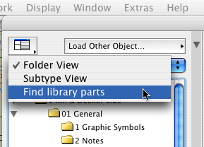
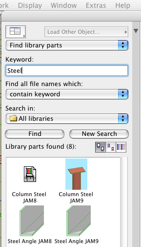
(I solved the screenshot problem by taking fewer screenshots.)


Pen table in Archicad...PM...

• Most work is done using the typical rows. The first pen is thinnest, at 0.04mm. Each sucessive pen is slightly thicker, up to 0.8 mm. The pens darken very slightly from left to right. The color change should not be apparent in general use.

For typical rows, the pens ending in the same number are the same weight. 11, 21, 31, 41, etc are all the same, they all turn black in layouts, where you can't tell them apart. Use the colors to differentiate parts of the model. Within the colors, set the line weight. Be consistent in what colors you use for different purposes. These are my habits:

Walls: Black (10's)
Roofs: Cyan (80's)
Doors & Windows: Brown (20's)
Soffits & Ceilings: Orange (60's)
Panel walls: Yellow (110's)
Counters: Purple (120's)
3D stairs, decks, terraces: Dark Red (50's)
Appliances, fixtures: Green (30's)
Main crown: Pink (70's)

When using the same color for different types of elements, make sure the types are spatially and conceptually separate. You can use your roof color for trim, but if you used it for ceilings it would get confusing.

For trim elements, use a different color for each type. I make the main crown pink and the baseboard dark red. If there's a chair or picture rail, I'll use cyan. This makes it easier to tell them apart when they're all stacked together.

Many CAD standards use color to represent output line weight. This is a help to drafting but is useless for model building. The most important issue for us is maintaining order and telling what is what. By using matching color for the plan, section, and fill pattern pens, the element will be recognizable from any point of view.

Fill patterns in section (brick, stone,etc) should have pen 11 (or 21, 31, 41,...). Composite separators that aren't set to hide should have pen 12 (or 22, 32, 42,...). Use a 13 (23, 33, 43,...) weight pen for edges in plan, such as counters and stair treads. Weight 15 (25,35,45,...) is used for cut elements in plan and section. I didn't forget 14 (24,34,44,...), it's used for the cut pen on elements that are either thin, curvy, or small, making the 15 weight seem too heavy.

The heavier pens in each row are there if you need them. You usually don't, and having so many is overkill, but we don't need the space. I use pen 36 instead of 35 for the cut pen of a site mesh, so the grade line is heavier.

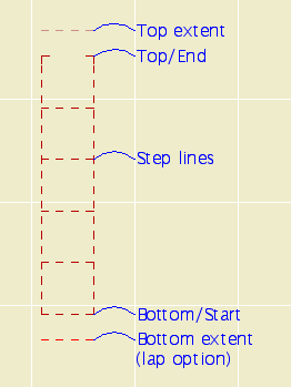
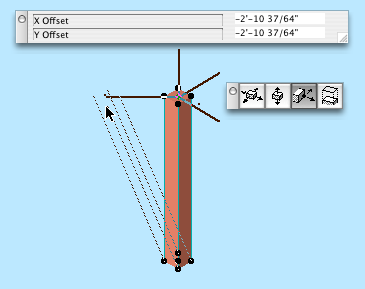
The last pen of each typical row is consistent in color but not in weight. Each n9 pen is 0.2mm thicker than the previous; 19 is 1.0mm, 129 is 2.8mm. See image.

• Pen 1 is black. It has the same weight as pen 15. Pen 2 is an anomaly, we shouldn't use it but we do. It has the weight of pen 13. We use it for structural slabs and decks in plan. In section, these slabs use pens 11 and 15.

• Pens 3 through 9 are used for differentiating things that don't print, and therefore don't need a particular line weight. Especially S/E elements. I organize my sections like this:

Exterior elevations: 9 (purple)
Long sections: 4 (green)
Cross sections 3 (orange)
Interior elevations: 6 (cyan)
Wall sections: 7 (blue)
Sometimes you have to cut a section just to generate a detail; I use pen 5 (dark red) for those.

Pens 6 & 7 are used for dimensions. They have special weights and your dimensions won't look right with other pens.

• Multiples of ten are an odd group. They used to be mostly white, but lately we've found the need for several dedicated pens, and this is where they are.

Pen 10 is the primary guideline pen. It is white in PM.

Pens 20, 40, 60, and 80 are all white in PM. I use 20 for junk sections, and 80 for white masking fills. Use these pens for anything you need to see but not be distracted by, or anything that needs to print white but be visible in Archicad.

Pen 30 is for the marked distant area of a section. It is gray in Archicad, and plots as a fine black line. When using marked distant area, always "Use One Pen" and choose pen 30.

Pen 50 is the dedicated poche pen. It should be the background color of most cut elements in new construction.

Pen 70 is light orange, and is intended for beam centerlines. The default was white, but they were hard to see. It plots white, and the display options turn the beam centerlines off for output anyway.

Pens 90 & 110 are white. They don't have any particular purpose as of yet. Don't use them. When you need a white pen that's white, use pen 91. It will never change.

Pens 100, 120, 140, 160, 180 are part of the grayscale pens.

Pen 140 is a thick, white pen for making wall-masking hatches for structure plans. More on this later.

Pen 150 is for material (surface) fill patterns. This means cover fills, 2D floor finish fills, and the vectorial pen of materials.

• Pens 141-149 match the weights of a typical row, but they plot at 50% gray.

• Pens 91-100, 111-120, 131-140, 151-160, 171-180 are the grayscale pens. They plot as they are seen in Archicad.

Again: For white white, use pen 91, and no other. Also, never change the color of pen 91. The whiteness of 91 is deeply embedded in Archicad culture. Most (all?) library parts with white in their symbols use this pen, because it's a given that no one will change its color. Other white pens, you can't be sure. Eg, pen 30 used to be white, now it's not.

• Pens 161-170 & 181-255 are not used. Archicad provides 255 pens for compatibilty with AutoCAD; it's really too many. Pen 255 is black in case you put in a pen number greater than 255 by accident, which gives you pen 255. If this pen were a color, it would print in color, causing your plots to have gray lines.

All Entries | 1 | 2 | 3 | 4