
This is our 'stair helper'. As described here, I'm not a fan of all-in-one solutions for stairs or other complicated assemblies. I would rather build from discrete parts, each of which does its own job well. The main structure of a stair consists of slabs for landings and Stair Body objects for the flights. The railings and newels are separate.
The RiserMeter is one piece of the whole stair method complex. It performs several helpful tasks:
• It helps 'calculate' the stair.
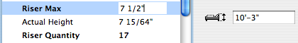
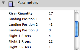
Set the height of the object, or use Automatic Height, which sets the height to the distance from the home story to the next story. Set the Riser Max, and the object will calculate the Riser Quantity and their Actual Height. (Note: After placing the object, open it and close it to ensure the story height gets picked up.) Or set the Riser Quantity manually, and the object will calculate the Riser Height. It's easy to add or subtract a riser and see the effect on the height.
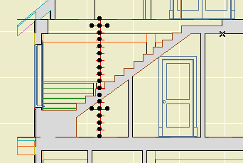
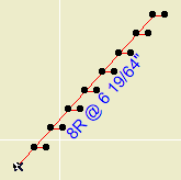
• It guides the vertical arrangement of landings and stair flights in section.
Once the risers are set, you can view the object in a section. There's a node at each tread elevation. You can slide the landings around vertically and then set the stair body objects to meet them.
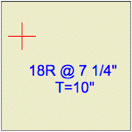
• It can annotate the riser and tread dimensions and quantities for the floor plan.
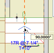
The text can be dragged away from the main object, and rotated to match the angle of the stair. You might want the 'stick' in a certain position so you can work with it in section, while the note text needs to sit on the stair.
The text can be shown on the home story, one story up, and one story down. The display, position, rotation, and 2-line setting of each text is independent.
If you're not going to use the note, you can put the object on a non-printing layer such as ! Guide.NP. To see the note, you need to use an annotation layer such as +A Arch Note Reg Scale. In this case, you don't want the 'stick' or the cross in plan to print. The White Pen parameter is used for this purpose. Printed white, the stick is virtually invisible in section. If you have a case where it is visible against a background, you can turn the 3D off.
To me, the design help function of the RiserMeter and the annotation function are far apart in workflow time: By the time you are annotating the stair, the design is fixed. So you could handle the display solely with layers, moving from hidden to showing at the CDs stage. Or use two objects. Etc.
Obsolete IMO