
In Archicad terminology, a marker is a special object that has a subordinate relationship to another element, representing the element and/or saying something about it. Viewpoint markers represent viewpoints in project windows. Each viewpoint type has its own marker objects. There are default markers for each one in the Archicad library, but we (as usual) use customized stuff. Each marker is dedicated to a viewpoint, but all the markers have a lot of parameters in common. Here I will lay out those similarities, as well as the special features of each marker, while making sure we're clear on the correct marker for each viewpoint type.
Remember that markers can be Source (creating a viewpoint) or Linked (calling out a drawing*). Additionally, a Source marker can refer to itself (a viewpoint) or a drawing based on itself. Our markers are designed to express the state of these conditions.
If a source marker is referring to the viewpoint, the bubble will display the ID and name of the viewpoint. This is the information you see in the Info Box or settings dialog when the section (e.g.) is selected. It has nothing to do with the name and sheet number of any placed drawing. Because it's not referring to the drawing, right? In this situation the text is written with pen 10, the red pen that prints white. If the marker is on a printing layer, it will appear blank in the output.
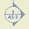
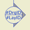
If a source or linked marker is referring to a drawing, the bubble will display the drawing number and sheet number of the drawing. The text is written with the pen of the marker, which will print black. If you see '#DrgID/#LayID' in the bubble, the drawing has not been placed yet. This can happen if the marker is set to refer to 'the first placed drawing' of either 'the viewpoint' or 'the selected view'. Once you actually place the drawing, the marker will fix itself.
Sometimes marker text will not display properly, even though you're doing everything right. Try flipping the 'with marker reference to' setting back and forth. Don't fiddle around with the source/linked setting.
In summary, a marker's text can appear three ways:
In the end, all markers in the output must refer to placed drawings. At some point all the blank and '#DrgID' markers have to be brought into line.
Diameter is the on-paper size of the marker circle.
Fill Pen is the fill color of the other polygons in the marker, the triangle points and the 'tail'. This is pen 95 (50% gray) by default. If the pen is zero, the marker pen is used, which prints black.
Fill Circle puts opaque white fill in the circle, which allows it to mask elements beneath.
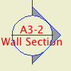
Section: Section marker JM11. Wall sections use the same marker with the Wall Section option on. To move the bubble to the other end of the line, turn on the Flip parameter. Junk sections use Plain Section JM11, the one with two tails.
Elevation: Elevation Marker JM11. The Int Elev Mode parameter turns of the side points so it looks like a single-sided IE marker. (There are occasions you might use the elevation tool to create an IE. Specifically, the IE tool doesn't offer the Marked Distant Area option.)
Interior Elevation: For Singles, IE Single Marker JM11. For groups, IE Group Marker RND.
Worksheets: They can have a marker like any other viewpoint, but in our workflow they never do. If you find yourself wanting to refer to a worksheet, you need a detail instead.
The 'Linked' idea becomes more prominent when discussing details. Considering linked markers as a whole, the detail tool will be used to place most of them. It would be rare, though possible, to place a linked section or elevation marker using those tools. Remember that you can refer to any type of drawing using a linked detail marker. Example: Wall sections are section viewpoints, but you would call them out within building sections using the detail tool, and the Detail Area marker.
Further, of our (current) five detail markers, four are always placed Linked. The exception: If you are creating a detail from existing geometry, use the Detail Area JM10 marker, placed with a 'box' geometry method.
Detail Area JM10 is a dashed box with a circle off the corner. There are parameters for the Corner Radius and the Tag Offset. Always place it with the 'box' geometry method; if you forget you'll see this:
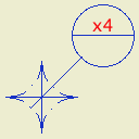
Delete it and do it over. All the other detail markers are placed with the 'spot' (first) geometry method.
For standard assemblies such as walls, use Assembly Marker JM10. It can be stretched to fit the thickness of the assembly.
Detail Flag JM10 is the one-sided section-looking thing with the tail. The tail and bubble can switch ends using the Flip parameter, exactly like Section Marker JM11.
Detail TagOnly JM11 is just a circle, and Detail TextOnly JM11 is just text.
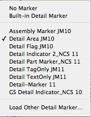
Don't be distracted by the AC library markers. If it says NCS, or doesn't say JM or RND in some form, don't use it. Again, I have no control over those other markers showing in the list.
Before AC11, sections and elevations were a unified tool and they both used SectionMarker JM10. This marker is still available in the list, for backward compatibility. Don't use that either; it will not refer to drawings correctly.
Believe me, I share your frustration with the marker choosing interface. It is ridiculous that we can't sort out the old from the new and the food from the trash.
Section and Elevation markers go on +Z SE Hide or +Z SE Print. Guess what the difference is. The preset sections and elevations in the templates are all on +Z SE Hide. As you develop these drawings and want to show the markers in the plan, change their layer to +Z SE Print. Note: Around the same time, you will switch the reference from viewpoint to drawing.
Interior Elevations have a matching pair of layers on the same principle. +Z IE Hide and +Z IE Print. There are no preset IEs in the templates for obvious reasons, but you still may find yourself creating them before you're ready to call them out.
In non-plan windows, all markers go on a Note layer, usually +A Arch Note Reg Scale. If you are using the Drawing Area marker to call out an enlarged plan in the regular plan, that also goes on +A Arch Note Reg Scale.
Create viewpoint: Marker refers to viewpoint
Create view or use clone
Place drawing
Switch marker reference to drawing
For section, elevation, or interior elevation, switch layer to Print
To refer to that drawing from elsewhere: Place additional Linked markers.
To refer to independent details, such as assembly types:
Merge or hotink as needed
Create view or use clone
Place Linked markers
To refer to PDF details in layouts, such as scanned structure stuff
Place drawing
Place Linked markers
* Linked markers are technically allowed to refer to viewpoints instead of drawings. Personally I don't see the value in this feature. I think it simplifies the workflow if the only viewpoint a marker can reference is its own. If a marker is Linked, it should be to a drawing only.