On Land

Environment Information
At Rill Architects we run ArchiCAD on macOS. If you work at Rill, this is your stuff. If you don't, but you work in ArchiCAD, you may find something interesting. Anybody else, I don't know.
RSS
Archicad Archive

« Newer | All Entries | 1 | 2 | 3 | 4 | 5 | 6 | 7 | 8 | 9 | 10 | Older »

If we had this model view option, it would greatly help the scale-sensitivity problem for composites and profiles. Background only for small scale output, detailed fills at large scales.

I've wanted scale-sensitive composites as long as I can remember. This seems easier? Note the cover fill option right there. Drafting fills too, sure. Consistency.

Solid Background On Cut Fills Please

These guidelines are current as of Archicad 17-18.

More»

Renovation is a feature set to control the display of existing, new, and demolished elements in the workflow of addition and renovation projects. It began in Archicad 15. This feature means we no longer have three of each layer in addition projects.

In the Renovation workflow, there are three kinds of elements: Existing Elements, Elements to be Demolished, and New Elements. This property is the Renovation Status. With a few unimportant exceptions, all elements have a renovation status, and it cannot be blank.

Renovation Filters control whether and how elements of the three statuses are displayed. Filters are saved with Views.

The filters control whether the elements of each status are Shown, Hidden, or Overridden.

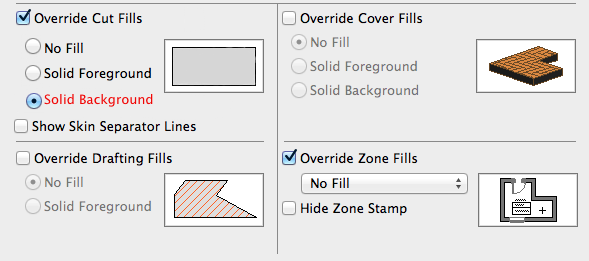
I hope showing and hiding are self-explanatory. If elements are overridden, their appearance is controlled by Renovation Override Styles. The attributes covered by the styles are: Line type; Line pen; Fill type, pen, and background pen; and material. There is no consideration for fill category, so cover and cut fills are handled the same. (Fail.) There is only one set of override styles, and they do not vary by filter. (Another fail.) For example, you can't have one filter where overridden demo elements are dashed, and another where they are dense dashed. Whatever the style of overridden demo elements, that's the style for all filters where Demo is overridden.

Because the override styles are responsible for the appearance of overridden elements, elements of different status will have the same "natural" settings. You don't change the line type or fill color of individual elements to show they are demolished.

The styles are set in the template and should be considered set-and-forget.

There are also Additional Filter Options for existing and demolition elements. Right now the only one of these we are using is to turn off markers for doors and windows.

Renovation Palette
The 
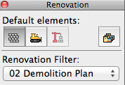
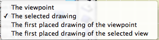
Renovation palette allows the user to control the current filter, the default status (of elements when they are placed), and the status of selected elements. It also gives access to the Renovation Filter Options and renovation override styles. The palette must always be open when working on addition/renovation projects.

And, keep an eye on it, it will try to mess with you. The current filter can change by viewpoint; it can be new construction in plan and existing conditions in 3D. When this happens, stuff will "disappear". Check the palette. Once the filter is set for a given viewpoint, it seems to stay put. (Both the default filter and the default status seem to sometimes change spontaneously, especially when opening a project on a different machine.)

The status setting is not transferred by eyedropper/syringe. The default setting on the palette always controls. You can change the status of an element in the settings dialog under Tags and Categories, but the palette is obviously easier and a better habit.

Our Override Styles

New elements are never overridden, and have no override style changes. (N.B. This is our decision, not a design limitation of the new status itself.) New elements act as if the filters don't exist. The background pen is gray (#50), same as it ever was.

Existing: The fill is overridden to be Empty Fill. The fill background pen is overridden to be pen 91 (white).

Demolished: The fill and fill background are overridden like existing, and the line type is overridden to be Dense Dashed.

Again, the natural settings of existing and demolished elements are the same as new. The override style turns them white and/or dashed.

See the appendix at the end of this post for examples of the different kinds of output.

Our Renovation Filters

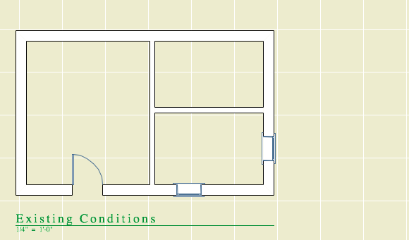
01 Existing Conditions
Existing: Override
Demolished: Show
New: Hide
This is used for building the existing model, and publishing the existing plans and elevations.
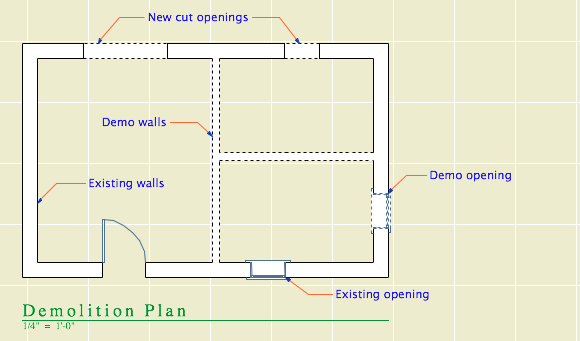
Existing Conditions

02 Demolition Plans
Existing: Override
Demolished: Override
New: Hide
All the walls have white background, and the demo elements are dashed.
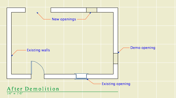
Demolition Plan

03 After Demolition
Existing: Override
Demolished: Hide
New: Hide
Existing elements only, with the demo elements removed.
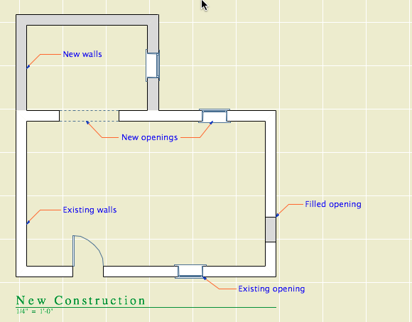
After Demolition

04 New Construction
Existing: Override
Demolished: Hide
New: Show
This is used for most work and output. Existing walls are white, new walls are gray.
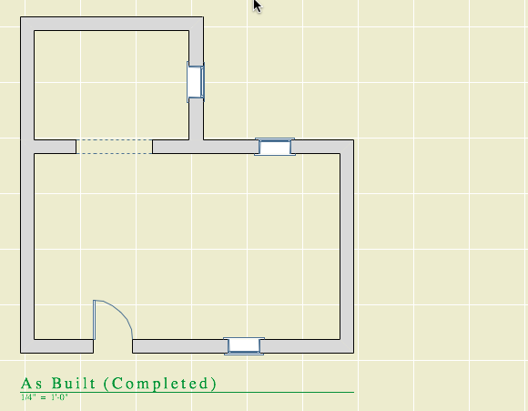
New Construction

05 As Built
Existing: Show
Demolished: Hide
New: Show
This shows the project when finished, as if it were all new. All the walls are gray.
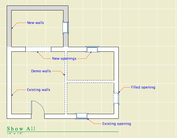
As Built

06 Show All
Existing: Override
Demolished: Override
New: Show
All statuses are shown, and you can tell the statuses apart.

Show All

How to Demolish Things

Select an element and, on the renovation palette, click the demolished button. That changes its status from Existing to Demolished. Unless the current filter is Demolition Plans or Show All, the element will vanish. If you switch to Demolition Plans, the element will reappear with dashed lines.

Wall demolition
Demolishing a wall

That's basically it. Of course, you might have to split an element first to demolish only part of it.

The big difference between the new method of demolition and the old layer-based one is in the handling of doors and windows. Doors and windows are now demolished the same way as other elements. Just select them and change their status. There is no need to split the wall and demolish the piece with the opening in it. When you demolish an opening, it is replaced by a portion of new wall. (Note: That new piece is shown using the natural settings of the existing wall. It's no longer being overridden. That's why all elements have the same natural settings.)

Doors

Further, you don't need to split an existing wall to place a new opening. Just place it normally (check the status!), and you will have a new-status opening in an existing-status wall. And in the demolition plan, the new opening location will be shown dashed.

Renovation Filters in New Projects

Unlike layers, renovation filters have only one purpose. (There's not going to be any hacking the demolition status to do something else.) If there's no renovating or demolishing, you don't need them. So in the New Home template they are not used. The filters are in there, but they are modified to show all statuses all the time, with no overrides. All the views are set to Show All. The palette can be put away.

Special Cases Where Multiple Layers Are Still Needed

Even on a New Home project there are some sneaky existing conditions, those pertaining to the site. We have separate layers for existing and new topography contours. We have layers for existing, "demo" and new trees. We have an optional layer for backing up the existing site's mesh.

I don't think these things are what renovation filters are for, and I can't see "using" them throughout a New Home project just to address these tiny parts of the project work. So we ignore the filters, and we have a few oddball E and D layers left. To remove a tree, change its layer and enjoy the nostalgic moment.

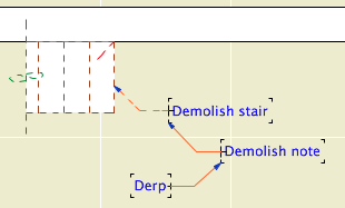
Don't Demolish Notes, Silly Rabbit

Demo derp

Another layer we didn't delete is +D Demo Note. I have heard of people trying to use one note layer and then make some notes demolition notes by changing their status. This is a category error. Renovation status is for project elements, which represent real things in the world. You're demolishing that note, are you? How? What is the result of demolishing it? Keeping different types of annotation straight is a proper use of layers.

And if we still have the Demo Note layer, we still have the Demo Plan layer combination.

Changes to the Templates

Removed lots of layers.

Implemented renovation filters and override styles.

Applied filters to views.

Updated favorites and default layers.

Created pen set for existing plans.

Secondary Info on Renovation

All element types have a renovation status except hotspots, drawings, figures, and viewpoint-creating tools (Section, etc.).

Elements have a setting in the Tags and Categories division where they can be set to show only on a specific filter, rather than "All Relevant Filters". There's also a button on the renovation palette for this setting. I can't imagine an occasion to use this. That setting is where the warning comes from when you delete a filter: "By deleting a renovation filter, you will lose all elements which are shown only on that specific filter." Since we don't use that setting, we aren't scared of this warning. Further, I don't see the need to delete filters very often.

The filter settings can be imported and exported; they are xml files like Model View Option combinations. (But they import badly, extant filters can't be overwritten.)

There seem to be no GDL globals for renovation status, which seems like a missed opportunity.

As of Archicad 16, sea level is part of the new Project Location dialog box. (Options -> Project Preferences -> Project Location)

The sea level value is the elevation of project zero in the real world, which is usually the framing floor of the main story of the building (Story 1). This value is entered as a positive number in Project Information.

Project Location

It gets automatically copied as a negative number to the Reference Levels, where it is locked and only for display.

Reference levels

With sea level set correctly, you can build your site model mesh using sea level topo data. Level dimension texts have autotext elements that can refer to sea level. Our standard story level markers and elevation marker objects can refer to sea level or project zero.

If you change the actual elevation of the project, you need to recalculate the sea level value and change it.

Sea level and the other reference levels are only for display and input assistance. Elements are always placed relative to their stories and project zero. If you change sea level, you don't have to worry about your site mesh moving around, even if you used sea level values to set it up.

Intersection priorities help the user control interactions between certain elements. Wall and beam elements have their own intersection priority; I'm calling that the element priority. Composite skins (and components of custom profiles) have their own intersection priorities. Those are skin priorities. Neither of these should be confused with the intersection group number property of layers, though that bears on intersections too!

Element priorities effect plan and 3D geometry. Skin priorities effect only plan. Managing skin priorities is the key to proper automatic joint cleanup between composite walls in plan. Here's a look at the essentials of skin priorities and our standard composite setup.

More»

Update: This method works through Archicad 12, with the key Recent Files. In 13 through 15, it still works, but the key you need to modify is called "Recent Documents". In 16, the Recent Documents key disappeared. Unfortunately I haven't been able to find where the recent documents are stored in 16 and 17.

Also: Under Mavericks (OS X 10.9), the developer of Pref Setter comes up as unidentified, and the current version will not run without modifying security preferences. The old version (I have 1.2.2) will run and seems to work fine.

It may happen that you would like to manually hack Archicad's recent files list. Recent projects are shown in the Start Archicad dialog box when AC launches. Recent projects and library parts are shown at File -> Recent Documents. One good reason to prune this list is that you can get apparent-duplicate items if you open a files from different locations, such as a server v. a local folder. Another reason is if you change servers and you need to make sure the recent items have the right address.

These are OS X instructions. We use the free utility Pref Setter to edit plist files. On Windows, use whatever Windows users use.

The AC preference files are at [home]/Library/Preferences/. There are a number of AC prefs; the one we want is com.graphisoft.AC .plist. You can right-click on the file and choose Open With... Pref Setter, or open the file from Pref Setter's File Menu.

The Pref Setter window will present all the 'Keys' in the plist file. Scroll to Recent Files.

Recent Files

Projects are listed first: Plan File_1., Plan File_2.,... You can delete any of these items. You can also modify the path in the Value field, to point to a different server, for example. Following the projects themselves, there is a Plan FileType_ item for each project. If you are deleting project items, you can delete these items as well, or not. It doesn't matter. Following that is a Plan Number item. This value is set automatically; you can ignore it.

After all the project list information, there is a similar arrangement for recent library parts that have been created or opened for editing. In this context the word 'Symbol' means library part: Symbol File_1., Symbol File_2.,... You can delete or hack these exactly like the project items.

(There are also integer keys for the number of RecentPlans (projects) and RecentObjects (library parts) you would like to see in the list. These are set to 12 by default, perhaps you would like more or fewer.)

We had to do some of this recently when we moved our projects, libraries, modules, etc. to a new server with a different address. When AC launches, it will try to make sure the recent files are accessible. This may lead to a prompt to log in to the missing server. Or, if the password for the server is stored in the user's keychain, the old server volumes can mount without you noticing it. Next comes confusion about where you are actually working, which is never good. Tip: Delete the password to the old server in Keychain Access. That way, you will be notified when AC wants to go looking where it shouldn't and you need to hack your prefs.

(To be honest, even after carefully working through this, I have seen AC mysteriously seek out the old volumes. There's some glitchy behavior going on, but it seems to settle down over time. We do what we can.)

All 3D elements have a User ID, known simply as the 'ID'. It can be observed and edited in the Info Box (near the top in our setup) and in the Settings dialog under the Listing And Labeling division.

The only 2D element with an ID is the Fill.

I wish other 2D elements had IDs. Then I could 'name' topo contours after their elevations.

You can access the ID field of a selected element by typing 'I'.

If the default settings ID ends with a number, the number will increment (increase by one) as elements are placed. Unless you switch off this preference in Preferences -> Miscellaneous. N.B.: The numbers will only cycle through the available numeric places. I.e., ABC9 will be followed by ABC0, but ABC09 will be followed by ABC10.

The default IDs of the tools in your templates should consist of an identifier for the tool (E.g., 'Roof' or 'R') followed by at least two digits, maybe three. This gives the incrementing room to operate.

Other than the automatic increment, Archicad never changes IDs by itself, and there's no problem with elements having identical IDs. (This is different from viewpoints, where the name/ID combination must be unique.) When you drag-copy or multiply an element, the copies will have the same ID as the original. When you eyedropper (alt/opt+click) an element, the ID of the next element will match, but the next one will increment, assuming the switch is on.

The ID is picked up by the eyedropper, but an existing element's ID isn't changed by the syringe.

I keep that Auto-increase preference on, and the only time it bugs me is when I'm placing Shape Tag objects for revisions, and I have to make sure the triangles say 2, 2, 2 instead of 2, 3, 4. (Really, that's just an illustration, because that object has a setting to use a custom text instead of the ID, but using the ID is easier because you edit it directly by typing 'I', bla bla bla)

Letter IDs do not increment, which makes sense now that I think of it. (WALL, WALM, WALN,... that's no good.)

If an element has an error in it, the ID will often appear in the report window warning. This is helpful, because you can use Find and Select to find elements by their ID, then track down the problem from there.

When you're searching for errant elements in this way, you will probably find many of a given ID, because of the drag-copying and eyedroppering described above. To isolate the troublemakers further, you can manage element IDs using a schedule.

We schedule doors and windows by their IDs, and you can change IDs directly within the schedule.

The only element type we deliberately give a blank ID is doors and windows we want to leave out of the schedule. This includes empty openings and weird openings like trim panels.

Zones have the same ID field as other model elements, but we ignore it in favor of the Zone Number field.

The GDL global variable for user ID is GLOB_ID. Elements also have an internal unique ID which is unmodifiable and invisible except in GDL. That global is GLOB_INTGUID. (I promised you trivia.) I can't recall using that one, but you need GLOB_ID all the time for markers and labels.

Somebody asked:

I have finally gotten frustrated enough with the way line types are (dis)organized to focus some effort on it. Have you figured out any tricks to getting line types to show up in any logical sequence at all in your files? I can't believe that after all this time GS hasn't just made it alphabetical. How hard can that be...?

Linetypes are sorted by their internal ID. All attributes (pens, materials, fills, etc.) have an internal ID. This ID is never visible in the general Archicad interface, though it winds up being very important. In settings dialogs, object parameters, and within other attributes (E.g., a composite uses a fill), the ID is what matters, not the name. The only place you can view and (sort of) manipulate IDs in in the Attribute Manager.

The other attribute types sort alphabetically in their lists, but for some reason linetypes don't. There's no excuse for this from the user's perspective, but you've probably noticed it's not the only charming eccentricity of AC's interface.

If you want the linetypes list to sort in a predictable way, you will need to hack their IDs. This is both a pain in the chair and not entirely free of risk.

If you change the geometry and/or name of the linetype at ID #4, all placed instances of linetype #4 in the project will change. If library objects have linetype #4 in their default parameters, suddenly they will have new defaults in those linetype parameters. Elements only care about IDs. Modifying libraries to adapt to such a change is prohibitive. Where the Archicad library is concerned, it's practically impossible because it's bad form to modify it at all. And, if you modify your own library, you have to be wary of affecting past projects going back however far, should you ever reopen them.

I did try to sort my linetypes a few years back. I survived, because we don't actually use very many, and I did some investigation to see what linetypes the AC library cares about. There is compromise involved. Our primary dashed line is at ID #2, but the AC library expects a dashed line at ID #4. If I put something else at ID #4, AC objects will display that instead of a dashed line. If I delete ID #4, those objects will have a missing linetype, which renders as solid, same problem. Meanwhile I can't abandon ID #2 because my libraries are hooked to that. So I'm stuck with two dashed linetypes at the top of my list, nothing I can do.

One more thing: If you do whip your list into shape, it will still be two lists, with the symbolic types following the vector types. Like symbolic and vector fills, that sorting can't be hacked.

As for how hard it might be for GS to fix this sort of thing, well, empirically it looks impossible. Hope to proved wrong.

Autogroup: On
Hide locked layers: Yes
Pet Palette movement: Jump
Tracker: Off
Coordinate Box: On
XY Button: Up
RA Button: Down
Move the origin a lot: Yes
Do that thing where you rest the cursor on a point and enter distances followed by + or -: No
Magnet: On
Info Box: Vertical
Navigator Preview: Off
Quick Layers: Off (Toolbar buttons)
Surface highlight selection: On
Contour highlight selection: Off
Info Tag: On, 100 second delay

I guess Autogroup isn't really an interface thing.

Or, seen and not seen. Fills, white pens, and materials.

More»

The user has requirements. The software has capabilities. Where the capabilities end and the requirements keep going is a limit. To get beyond the limit requires workarounds. Some limits are harder than others and all we can do is wish (beg) them removed.

Here's a rich example concerning structural posts (columns) in residential construction. These are things like 4x4s, multiple 2x_s, steel pipe columns, tube (TS) shapes, and the occasional W shape placed vertically. Hard limits in Archicad are in bold. Stuff I've figured out is the rest of it.

More»

A reference marker is a special object that can intelligently refer to viewpoints within the project or drawings placed on layouts. They also create viewpoints, which is a strange kind of double duty. Then you can also create viewpoints without markers... it's not intuitive overall. For most cases, you can think of a viewpoint as an application window. Sections, elevations, interior elevations, details, and worksheets are all viewpoints. So are schedules and even stories, but they are not related to the marker discussion in the same way. Everything in here applies equally to sections, elevations, and details.

A source marker creates a viewpoint. It is the viewpoint, in a manner of speaking. If you delete a source marker, you delete the viewpoint. If you copy a source marker, a new, additional viewpoint is created.

A linked marker is more like an object, though still a special one. When you place a linked marker, no viewpoint is created; the marker points to something. Any number of linked markers can point to a particular viewpoint or drawing. They are just pointers, and they can be created or destroyed without affecting anything else.

Both source and linked markers can refer to drawings.

You can have a viewpoint with no marker. Such a viewpoint is independent. You will very often have independent details. At this time all of our worksheets are independent. You can even have independent sections and elevations, but I don't see any advantage to these. Interior elevations can't be independent.

Choosing Source or Linked

When you get ready to place a marker, whether to draw a new section or refer to an existing detail, you will see these choices in the info box:

Marker creation options

When you select a marker, the options look like this:

Marker selection options

You can turn a source marker into a linked marker and vice versa, but don't. It's complicated, potentially destructive, and I'm pretty sure it's silly. Treat your viewpoints as 'real' things, and use linked markers to point to drawings in any way you like.

With Marker reference to
Marker ref to viewpoint
In our usage, markers usually refer to drawings in layouts, though they can also refer to viewpoints. Before a drawing is placed, source markers should refer to their viewpoints. In our section, elevation, and detail markers, you can tell the marker is referring to the viewpoint because the ID and name of the viewpoint are shown in the tag. The text is written with pen 10 (red), so if you print them they will appear empty.

In practice, a linked marker should always refer to a drawing. It makes for a smoother workflow if you place the drawing in the layout before placing linked markers.

When you choose to refer to the drawing rather than the viewpoint, you have three choices.

Marker reference to

The selected drawing lets you choose the drawing manually from the layout tree.

The first placed drawing of the viewpoint means you don't have to choose the drawing. The marker will find the first drawing of that viewpoint in the set and refer to that. You can choose this option before the drawing is placed. If you go this route, make sure the first drawing is the only drawing, or you are sure the first one is the one you want. N.B.: In our layout tree, the schematics sub-book comes before the CDs, so this 'first' thing will always use a schematic elevation instead of the same elevation in the CDs.

• Similarly, the first drawing of the selected view lets you name a view in advance of placing any drawing. When the drawing is placed in due time, the marker will refer to it. This 'first' method is safer, because 'view' is more specific than 'viewpoint'. For example, the schematics and CDs use different views.

With a source marker, you can only choose a viewpoint, view, or drawing associated with the marker's viewpoint. A linked marker can point to anything.

No drawing placed
If a marker is set to refer to a drawing but no drawing is placed yet, the tag will read #DrgID / #LayID. If you see this in a marker, it means the drawing isn't placed. Remember, if you see red text, the marker is still referring to the viewpoint.

Warnings about deleting markers

When you have a source marker selected and you strike delete, you will get a warning to the effect that deleting a source marker will also delete that marker's viewpoint, unless you choose to keep it as independent. If you confirm that you want to delete the viewpoint along with the marker, you be warned again, to the effect that deleting sections (e.g.) is not undoable. This second warning is as old as the section tool itself, and you know what it means.

If you delete a viewpoint from the Project Map, you will only get the warning about undoability. When a viewpoint is deleted in this way, its source marker and any linked markers are automatically deleted.

When you delete a linked marker, you don't get a warning, because nothing important or non-undoable is happening.

« Newer | All Entries | 1 | 2 | 3 | 4 | 5 | 6 | 7 | 8 | 9 | 10 | Older »