On Land

Environment Information
At Rill Architects we run ArchiCAD on macOS. If you work at Rill, this is your stuff. If you don't, but you work in ArchiCAD, you may find something interesting. Anybody else, I don't know.
RSS
Archicad Archive

« Newer | All Entries | 1 | 2 | 3 | 4 | 5 | 6 | 7 | 8 | 9 | 10 | Older »

MVOlist
Model View Options, formerly known as Display Options, can be organized into combinations, kind of like layers, and MVO combinations can be saved with views. Naturally, this is all set up in the templates. MVOs are completely separate from On-screen View Options, which are screen-only and do not affect output.

The MVO dialog has three divisions. Options for Construction Elements concerns the display of real things, including openings, columns, beams, and markers. Options for Fills and Zones concerns how different categories of fills are displayed; turning cover fills on and off, e.g. Options for GDL Objects has only one item at the moment, the beloved Story Viewpoint Type, also known as the ceiling switch.

The keyboard shortcut to open the dialog is Cmd+9. I think the MVO dialog is pretty good about previewing the effects of most of the controls.

Rather than describe each combination, or heaven forbid build a table, I'll describe the A1/A2/A3 combination, then how the others differ.

More»

Isn't north up? Probably not. Since the orientation of the project is driven by the geometry of the plan, north can be any which way.

Project North
In the Sun dialog
The north direction for the project is set in the Sun dialog. You get there via the Sun button in the Camera settings box, or via the More Sun button in the 3D Window Settings dialog. MORE: Karl Ottenstein points out that you can also go directly to the Sun dialog by right-clicking on any 3D viewpoint (camera, axon, etc.) in the Project Map, or on any 3D view in the View Map.

Note: Though it's called 'Project' north, it's true north, in that it's the only north, and the north used by the sun settings. Archicad doesn't directly support a project north environment variable separate from true north.

There are at least four reasons to set project north correctly:

• Accurate sun shadows

• Automatic orientation of north arrow symbol objects.

• Automatic dimensioning of metes and bounds using the Survey Dim RND9 object.

• Correct naming of interior elevations with the Orientation autotext. (A real project north would be nice here.)

For the purposes of sun shadows and interior elevation names, you can eyeball the north direction by moving the pointer in the Sun dialog. A degree or two off isn't going to hurt.

For the metes and bounds to work, you need to set the direction exactly.

More»

Every viewpoint has a name and an ID. The name is important and is often used for output. The ID is never used for output, but wherever possible we use the ID to help organize the project map and view map.

Info Box name/ID
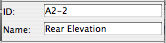
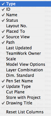
For viewpoints with with a marker, the name and ID appear in the Info Box and settings dialog. This applies to section, elevations, details, and interior elevations.

Properties in Navigator
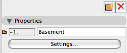
For all viewpoints, the name and ID appear at the bottom of the Navigator under the Properties heading. Viewpoints with fixed IDs, such as stories, will have the ID field in gray.

The behavior of IDs varies among the viewpoint types, so here's a cheat sheet.

Story IDs
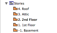
Stories have unique, fixed IDs based on the order of stories. They are ugly. We ignore them.
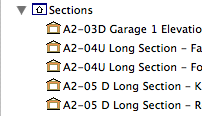
Section IDs
Section and 
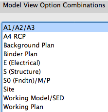
Elevation IDs are created by the user, and they need not be unique, but the name/ID combination must be. (If you try to create a section/elevation with an identical name and ID, AC will automatically append a number to the ID.) Sections and elevations should have an ID roughly corresponding to their sheet number. Building elevations and sections get A2-1, A2-2, etc., and wall sections get A3-1, A3-2, etc. For sections, add a letter to indicate the direction the section is facing. Don't put the direction in the name. For 'Junk' sections, used for modeling support and not for output, the ID should be xn where n is a number. Junk sections x1 through x4 are placed in the template. (Yes, junk sections should usually be sections, not elevations.) So you end up with a section list of output viewpoints at the top, followed by all the junk.

Interiors IDs
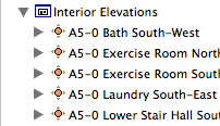
Interior Elevation IDs should start with A5. I like to use the ID to sort the interiors by story: Basement is A5-0, first floor is A5-1, etc. Like the sections and elevations, the actual output sheet may differ. The sorting is to help you know where to look in the view map.

Detail IDs
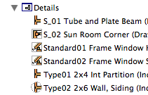
Detail IDs need not be unique. (In AC10 and earlier, they had to be.) Still, it's a good habit to make them distinctive. I find it helpful to use the detail ID to give the 'category' of detail. For example, a bunch of eave details will have IDs of Eave01, Eave02, etc. The assembly type details have Type01, Type02, etc. Structure detail IDs start with S_ followed by a number. For all details, the name should be presentable for the automatic drawing title.

Worksheet IDs
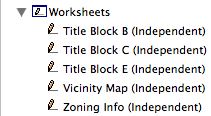
Worksheets are a new, mostly redundant viewpoint type in AC11. We could easily live without them, but since they exist, we park all the straggly non-detail drawing things there. There aren't enough worksheets in a typical project to worry about sorting the list, so I recommend leaving the ID blank and just using the name.

The primary Schedules have an ID to sort them to the top of the menus. Incidental schedules don't need IDs. This may change.

Cameras and paths have unique IDs that can't be changed.

Summary: Viewpoint IDs are not used for output, so use them to help sort the lists. Names are used for output: Use the name you want to see on the paper.

The IDs that do matter for output are those of the layout book items; subsets, layouts, and drawings.

Drawing IDs are usually generated by the layout, either by the grid or the order of drawings in the layout book tree.

Layout IDs are usually generated by the subset.

Subset IDs are set by the user, and the subset ID becomes part of the layout ID.

Views also have IDs, but they should typically inherit the viewpoints' IDs, so the lists will appear the same to us. All view IDs can be customized or set to 'None', but you can usually just leave them be. In the templates, I have deleted all the IDs for story (plan) views, because stuff like "-1. Basement" looks idiotic.

Somebody asked why the flue object can't show a thickness for the flue liner itself.

Flue on Nothing
One reason: The flue sits atop, and lines up with, the top of the smoke chamber object. In section this gives a continuous void. If a thickness is built in to the flue, there would be a discontinuity at the top of the smoke chamber, and the flue would appear to be supported by nothing. Building the flue thickness should help make a better detail, yet this is worse. I could partly solve this by narrowing the top of the smoke chamber, but that doesn't help with the other, bigger, reason.

The other reason: The flue is designed with SEOs in mind. You have to use it as a subtraction operator, or there's no point. It is a simple solid tube (EXTRUDE, actually) which we use to make a simple void. If the flue wall has a thickness, it becomes a solid ring with nothing in the middle.

Flue Filled
When you subtract with a ring, you get a ring-shaped void, with solid, un-subtracted material in the middle. If you cut a section through such a thing, you'll get masonry fill with two stripes of flue-wall fill going through it, and no void.

Flue Air Fake Air
To fix that, I could simulate emptiness within the flue by filling it with solid stuff with a clear section fill. In order to see this stuff and the wall thickness, we would need to make the flue's layer solid instead of wireframe. The problem there is that in a marqueed 3D view, there would be no void.

Well, I could wireframe the layer in building section combinations and make it solid in wall section, and I could make the thickness option scale sensitive in the flue and the smoke chamber, but we're into serious inelegance now. It's a void, except when it's not and it's simulating a void, and it's scale- and layer combination-dependent, and do I 'really' subtract it to 'simulate' a void, I can't remember.

Once again we have met a limit in GDL object technology where the simplest solution is for Graphisoft to give us more power. There is a directive, MODEL, which allows you to build shapes in wireframe or surfaces-only mode in addition to the default, normal, solid mode. MODEL WIRE makes a wireframe shape that looks exactly like switching a layer to wireframe. MODEL SURFACE makes a shape that looks normal from the outside but is hollow. This sounds promising for our problem until we realize that only MODEL SOLID shapes can act as SEO operators.

Therefore, I want a new MODEL option which will make shapes wireframe, but which will allow the shapes to act as operators. So the flue wall would subtract, and the void within the flue would subtract, but the void would still be a void. My first stab at a name is MODEL OPERATOR, but I'm open to suggestions.

The Drawing Manager appeared in Archicad 10, taking the place of Drawing Usage in PlotMaker 9. You can open it by clicking the button at the upper left of the Navigator.

It lists every drawing placed in the project, displays various settings of the drawings, and offers tools for performing drawing-related tasks such as updating, changing the linked view, breaking links, and changing drawing element settings.

You can perform most of these tasks elsewhere on a drawing-by-drawing basis by right-clicking on a drawing element, or on a drawing item in the layout book tree. But Drawing Manager offers you a power-editing mode where you can modify many drawings at once. Examples:

• Update all the manual-update drawings.

• Change all the instances of a drawing title to a different object.

• Make all of one kind of plan use a new, specialized pen set.

The key to these mass-modifications is to organize the list by the various properties, by clicking on the column headings. There is similar functionality in the Finder and many other programs.

For example, to update all the Manual Update items, click on the Update Type column, highlight the Manual ones, then click the update button.

For another example, sort by Drawing Title to change all the Drawing Title JM10 to Drawing Title JAM10a.

Etc.

In Archicad 11 they didn't change the Drawing Manager much, but they did change the way you choose what columns to display. In honor of the occasion I thought I should point out which columns are most valuable and which you should leave off.

Drawing Manager Columns
If you right-click on any column header, you'll get this popup, where you can check the columns you want to see, and uncheck the ones you don't.

Columns can be resized by clicking and dragging on the joint between two headings.

If you look closely at the headings you'll see that one has a triangle and another has two triangles. The one is the last column you clicked, and the two is the previous click. This gives a two-level organization where the list is sorted by the last criteria, and within that, by the previous one.

These columns should be on:

Type. Plan, section, external file, etc.
ID. Of the drawing in its layout. Not critical, but it's little.
Name. Of the drawing, which will usually be the name of the view that created it.
Placed To. Name of the layout where the drawing is. (Usually a layout. Drawings can be placed in model windows, as you might a DWG. In this case that window would be listed here.)
Source View. Name of the view from the view map, actually the whole path, including the stupid '/Residence' or '/Addition' notation. This is the kind of half-baked design decision you make when you develop primarily on Windows.
Path. If it's an external drawing. Otherwise it says 'Internal'.
Pen Set Name. Pen set assigned to drawing element. All drawings need a pen set.
Update Type. Automatic or manual.
Drawing Title. Object name of the automatic marker, if it's in use. Plans, among others, don't use automatic titles, so this field would be blank.

What? I know how to open a file! Jeez!

OK. Just in case:

Always open AC files via right click -> Open With or by dragging the file to requisite AC icon on the dock. I do the dock thing; I'm just not a context menu person usually.

Most important, don't double-click PLNs. Double-clicking will only give consistent, predictable results if you have exactly one copy of AC on your machine.

When you install a new version of AC, as you soon will in the form of 11, that version becomes the default application for opening PLNs. So you double-click your AC10 project, it opens in 11, you don't notice the difference because there isn't much, you save it, and next time you try to open it in 10 it doesn't work. (Yes, backsave. Real convenient.)

Always keep current versions of AC on the dock. Even if you use the right-click method, the dock gives you visual confirmation that the right application is being used.

Graphisoft gives poor support in this area, by making the icons identical and naming each version, precisely, "Archicad".

Double-clicking files is one of those 'automatic' things that's great if you can trust it, but when it's not predictable it makes trouble. It's not just AC either, recently my .docs started opening in Pages for some reason.

What about that 'Change All' under Open With in the Get Info window? That fixed my .doc issue, but it doesn't reliably assign the right 'Archicad' version.

So, right-click or dock. If you have a bad habit here, change it now before 11 starts getting on your nerves.

Update re app icons: Mr. Briggs to the rescue.

11 Icon

Summary: With the model and the layouts in one file, pen sets manage the difference between the model pens and the output pens. In addition, they can do view-option-type tricks.

Background: In Archicad 9, there was one set of pens. In PlotMaker 9, there was also only one, and it could be different from the set in AC. Or, each drawing could have its own pens, but it was impractical.

Our standard has always been to use a colorful set of pens for modeling, which translates into a black/white/gray set of pens in layouts. We are far from unique in this arrangement.

In 10, they threw PM into the abyss, so they needed a method to maintain at least those two groups of pens within the new unified project file. So, Pen Sets.

More»

It's time.

I has 3DS

More»

GS Arrival
LCF Folder
Archicad 10 offers a new all-in-one library file format, the Library Container File or LCF. In Archicad 9, you could use a PLA archive file as a library. LCFs are pure library stuff, with no model space or attributes.

It is allegedly faster to load the libraries as a single large file than from folders full of folders full of individual objects. But I must say in my informal testing I haven't observed a dramatic difference among loading library folders, PLAs, and LCFs.

In addition, there's at least one characteristic of LCFs (and archives) that is disadvantageous. You can't save objects into them. So no new objects and no editing. (You could view this as an advantage from a standards point of view; nobody can mess anything up.)

In other words I considered using an LCF for the Rill & Decker Standard LIB but decided against it. There's no change in everyday library management.

But! There's a huge advantage to the LCF in one specific case: Copying libraries to a flash drive to take them home. The R&D library is about 15MB. Copying its 1300 or so items to a USB 2.0 drive takes over two minutes. Copying the same library as a 15MB LCF takes, drum roll, three seconds.

It also takes the guesswork or other syncing strategies out of keeping your home copy of the library up to date. Just bring the LCF home and overwrite the old file.

So I'm providing the library as an LCF for this purpose. The file lives at 2 Libraries / Library Container Files. I will do my best to update it when anything important changes. This is pretty often, so make sure you check it regularly.

You still need to manage project libraries manually.

In Archicad 10, sections can automatically show story level markers and lines. They are feature-limited but I think they're worth using.

More»

Detail Markers List
It lumps together all the markers of a given type in the loaded libraries. It provides no hierarchy, no way to say, 'use this marker, not the AC library ones, not the obsolete versions of the right one.'

The browser interface of the object tool etc allows the library person (me) to gracefully deprecate old objects, and steer users toward the good ones.

When we update an object, we move the old one to the xOld R&D folder. This folder loads, so placed instances of old objects will continue to work. The updated one is the only one visible in the proper folder, so there's no question about which one is right. There's a Center Line symbol, it's in Graphic Symbols, and that's it.

Can't do it with markers. The marker chooser makes things more confusing than they need to be. For example, on the detail marker list, three out of thirteen items are meant to be used.

« Newer | All Entries | 1 | 2 | 3 | 4 | 5 | 6 | 7 | 8 | 9 | 10 | Older »