These guidelines are current as of Archicad 25.

IFC is a format for exchanging models with data attached between different software. IFC elements are 3D construction elements and objects. IFC has nothing too with plans, annotation, or anything 2D.
The only consultant I have worked with is StructureCo, which is a pseudonym. The type of work is custom residential -- mostly wood members with some steel. This is our first try at this type of coordination.
My goals for the StructureCo collaboration:
• If I can get the beams labeled in the sections, and check that the structural elements fit, I can let them do the framing plans.
• Automatically label elements based on data provided within them, such as ID or profile.
• Let their layer names come through, with an extension.
• Bring in elements with proper classification.
• Avoid creation of attributes other than Complex Profiles.
• Let the consultant do the model 'their way' as much as possible. We try to be low-maintenance teammates.
In other words, let them do some of the work without sacrificing the consistency of our model and annotation process.
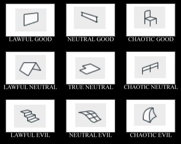
I didn't want to talk this to death. What I like about alignment charts is they are assertive rather than argumentative. You have to just look at them and work out the relationships among the things, and ask yourself if your impressions of the things agree with the author's.
I made this by instinct. The strongest notion I had was that the morph tool is chaotic evil. The second strongest notion was that the mesh tool is a relic and needs to be done over. Then I was on my way.
Having meditated on it a bit, I think this is what the axes mean:
The lawful-chaotic axis runs from standard orderly content to custom content. The good-evil axis runs from user flexibility to user frustration. With that, I will proceed to talk it to death with some comments on each item.
You don't need to use clones to create views, but I recommend them. To review, a clone folder is a viewpoint set such as stories, sections, details, etc., with view settings pre-arranged so that when you make a new story, section, or detail, a new view is automatically created with the correct settings. View settings are easy to mess up and there are a lot of them, and they directly affect output. Better to set up clones in your template, and have all your views perfectly set, even for viewpoints that haven't been born yet.
Some users/managers/template makers eschew clones in favor of placing dummy sections (e.g.) and moving them around as needed. That's OK, especially if your projects are of a consistent scope that you can prepare the template for it. Our projects vary in size a lot, and I like the user-proofing aspect of clones either way.
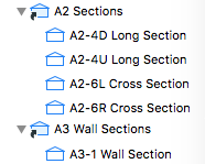
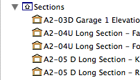
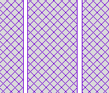
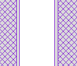
The only thing I don't like about clones is that they always clone the entire set of viewpoints. We have two clones of the sections: one for building sections at 48 scale, and one for wall sections at 16 scale. Both clones contain all the sections, so we sort the list using the section ID. Building sections are A2 and wall sections are A3, and then in each folder the user has to mentally tune out the sections that shouldn't exist. (And the junk sections, which are never used for output, appear uselessly in both.)
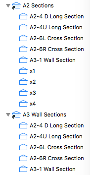
Junk trimmed for brevity
I'd like to see clones that could be filtered by ID, so that only the A2 sections appear in the building sections clone, and only the A3 sections appear in the wall sections, and the junk can be avoided completely.
Element Transfer Settings is a new feature of Archicad 21. It allows the user much greater control over what settings are injected during a syringe operation and/or when favorites are applied. I haven't explored the feature enough yet to be inspired by what it can do, but I think it's going to be helpful.
But I have a problem with the way the feature behaves in projects migrated from Archicad 20. When you open a project in Archicad 21 the first time, a single ETS option is created, Transfer All Settings. As you would guess, every setting in every tool is checked off. This includes settings that didn't transfer in Archicad 20, such as story, ID, and zone name and number. These are the personally annoying results that drew my attention:
• Favorites are set to include the story. So on every story except the home story when the favorite was created, you will get that wonderful dialog box about changes on an unseen story, and then you undo, fix the story, and do it over. (In 20 this just behaved badly and acted like a bug. It works perfectly now once you know what ETS is.)
• ID is included, so if you use unique IDs to schedule elements such as doors and windows, you are going to start to see duplicate IDs (i.e., data loss) from using favorites or the syringe.
• I don't think I've ever eyedropper/syringed a zone, but if I did, I wouldn't want the name and number to transfer, that's crazy.
The old way in Archicad 20 offered some control over these things, so if you wanted to transfer ID via favorite you could, though you couldn't via syringe. (That's really confusing and the new way is better, once you know about it.)
So a migrating user of Archicad 21 is probably going to encounter frustration and data loss, before they even meet the new feature that is responsible. The migration process should have created a safer default ETS option. Note, this is only an issue with migration - the templates have a sensible assortment of options.
I have only made a few ETS options so far, but my default one excludes story, ID, name, number, reference ID, title, and label text content. I have a separate option to transfer label content. And I renamed the bad one to: 'Transfer All Settings BE CAREFUL'.
Graphic overrides are a new feature of Archicad 20. They allow you to choose elements by criteria, and change their appearance attributes. The changes are grouped into combinations which can be saved with views.
Here's how to use Archicad: Build a model, and try to create all the documentation while doing the least amount of non-modeling. If you find yourself drawing something that you have already modeled, it must be because the thing can't be made to present itself in the appropriate way for your documentation. Archicad has always offered methods to help with this. A door can have a complex plan symbol, a simple symbol, or just an opening; it can have a schedule marker or not; or it can be hidden entirely. The same one door appears in 3D and in a schedule. One door, many appearances in documentation. This is unity.
Graphic overrides greatly expand the variety of ways that a single element can be presented. This means it is less likely that you will need to 'draw' an element you have modeled in order to get it to appear correctly in your documentation.
This feature gets at the heart of what Archicad is all about. It will definitely change a lot of working and documentation methods. If it doesn't, you are probably using Archicad wrong.
Since this is a major feature, it is impossible at this early stage to predict everything that will change. But I am getting a sense of what the categories of changes might be.
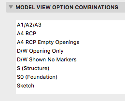
Beginning with Archicad 20, the fills division of Model View Options is obsolete and fills are handled by Graphic Overrides. This enables us to eliminate several combinations that were needed in Archicad 19.
These guidelines are current as of Archicad 19.
This is everything I can think of about libraries management. There have been a lot of changes over the years.
If this was a proper post it would be clearer and have some illustrations. These are just my notes on the process, quite involved for us as you'll see, of migrating a project to AC17/18. Even though 17 was released 18 months ago, we still have projects in earlier versions and I doubt we are alone. IMO, the combination of Building Materials and "Inside/Outside" for walls is the biggest change to AC modeling in my 16 years of using it. It's worse for us because we have a standard of interior wall reference lines, and AC is strongly biased in favor of exterior. No, changing this standard is not feasible.
When an AC16 file is opened in 17/18, building materials are created, several of each kind, based on cut fills of preexisting elements, and maybe favorites and tool settings. You need to sort the Bmats first, to make it easier to sort the composites later.
Sorting the Bmats: In Attribute Manager, open the current template. This has the good Bmats. In the template, here's concrete at ID 4. In the newly opened project, you probably have several concretes. Hopefully one of them has ID 4. Overwrite that one from the template. (In 17, all overwriting is by ID. In 18, you can choose to overwrite by name or ID.) Apply that, and you will get a confirmation that you are modifying the bmat as well as the surface.
Now that you have a good concrete, you can delete the others. You have to do this in the Bmats dialog, not the Attribute Manager. Select all the old concretes (the ones with the strings of numbers), delete and replace with the good new concrete.
Back in Attribute Manager, pick another Bmat that needs to be cleaned up, how about brick. Reopen the template (yes every time) and check that the ID of the template brick matches any one of the project's bricks. If it does, repeat the process above. (Overwrite, delete the others and replace with the good new one.) If it doesn't match, e.g., template brick's ID is taken by Empty Fill ########## in the project, postpone working on brick and choose something else. In the process of cleaning up the other Bmats, template brick's ID will eventually become available.
Keep overwriting and replacing, back and forth between the Attribute Manager and the Bmats dialog, until you have all good Bmats from the template.
Once the Bmats are done, you can do the composites. Some new composites are created, though the old ones remain. Composites are upside down because of the inside/outside thing, so the easiest way is to replace them from the template where possible. (Technically, they aren't upside down yet, but they will be once you flip the walls.) Because the old composites are kept, it's easy to line up the IDs with the template and you might be able to replace them all in one Attribute Manager session. Then in the Composites dialog, delete the items with the long numbers, replacing them with the good ones from the template. Unfortunately, for composites you can only delete them one at a time.
Changes to walls in AC17: They have Inside and Outside faces. The surfaces (formerly materials) are set by these faces, not by the ref line side. The ref line can be inside or outside face. The three surface attributes can take the surfaces of the wall/composite's Bmats, or they can be overridden. In practice they get overridden a lot, and in the overridden state they are just like the three attributes in AC16 and earlier.
This default Bmat/surface/override behavior is suspended when a project is migrated. There is a legacy setting in the Project Preferences for Construction Elements (In AC18 it is under the Legacy tab). It stops the new intersection method from working (the 3 digit number in the Bmat's settings), and also auto-overrides the surface attributes of elements such as walls. So the override button is not available for those settings.
If you turn the the legacy setting off, the override button will come back to life, with the override on. So you should see no changes to surfaces. What will change is the intersection behavior between Bmats. With the legacy setting off, the 3-digit priority takes effect, so you might need to tune those up to get the behavior you expect. One change you must make: The cutting layers need to be set to a high intersection number to prevent them interfering with ordinary elements. For a clear example, turn the legacy setting off, open a section, and take a look at what the site cutting slabs do to the basement walls. I'm using 100 for this intersection number in the templates. It only need apply to section, elevation, and 3D layer combination types.
There is no rush to turn off the legacy setting to keep working as you were. If you are purely migrating the project, i.e., archiving it in the most current version, I would leave the legacy setting on.
GS decided that most people have the ref lines outside, which I guess is true. For us it is false. When you migrate a project, the Inside/Outside setting has to be created from scratch since in does not exist in AC16. All walls are reborn in AC17 set to Outside Face. The ref lines are still inside, and the interior/exterior surfaces are architecturally correct, but it is not sustainable to continue working with this setup.
Even though the appearance is fine, logically it is intolerable. Here is an exterior wall. Its ref line is Outside Face, but that is the interior side of the wall. In the wall's settings, the interior surface (paint) is on the exterior corner icon, and the exterior surface (siding) is on the interior. There is no way to keep this straight going forward, especially if you are accustomed in ref lines inside. Further, those composites you imported assume the ref lines are inside. And, the Outside setting is picked up by the eyedropper. No, we need the walls to say Inside Face.
Fortunately, it can be done, using the Modify Wall Reference Line (MWRL) dialog. It's at Edit -> Reference Line and Plane -> MWRL. Option+W on the keyboard. There are two moves involved: Mirror Walls In Place puts the ref line on the other side while keeping the wall in the same location, though the surfaces flip. Edit Ref Line Location - Inside Face changes the ref line side setting and moves the ref line to the opposite face. In combination, these two moves switch the Inside/Outside setting while keeping the ref line in place (on the interior). Dimensions also stay put. There is one very unfortunate consequence, however, which is that the interior/exterior surfaces are now backwards. So for exterior walls and any others where the two faces differ, you have to change those surface settings manually. This could be anywhere from a minor pain to a huge pain depending on the project.
Wall favorites are also reborn set to Outside Face, so they need to be modified, or you can start over by reloading the favorites from our standard setup.
Some new complex profiles are created, though the old ones remain. Delete the new (##########) ones and replace them with the old ones. I don't know what the deal is here, they seem to be identical.
I think this process is far too cumbersome, considering that Bmats are not that big of a deal to us at the moment. Starting a project in 17/18 is no trouble at all, but this is by far the most complex migration we have seen since at least the death of PlotMaker.
It's fine to say don't migrate and finish the project in 16, except: You now need 17 to create BIMx files; GS won't give you the 16 version. And of course 18 offers the superior CineRender engine. So by staying in 16 you are hobbling yourself in presentation.
Most of the trouble in this migration is caused by the assumption that everyone has ref lines outside. It's because of this that our walls are outside-in, and we need the MWRL maneuver, and we need to manually fix all the exterior wall surfaces, and the composites are upside-down. All GS had to do was ask, when opening a 16 file, if the user's standard is ref lines in or ref lines out. I'm sure GS is correct that ref lines out is the majority, but the decision puts us in a bind.
It's also worth keeping in mind that you should generally migrate projects, and continue to migrate past project archives, because you never know when updates to AC or your OS will leave some of your data inaccessible. GS didn't get to vote on whether AC9 would stop working in OS X 10.7. They (presumably) didn't know AC10 and 11 would break in 10.9, and while they fixed them that time, they certainly didn't have to, because generally only the last two versions are "officially" supported. You need AC10 to open anything older than AC10, and the next major OS could break it for the last time. So you need to migrate and keep migrating; archives that are eight versions behind are not a sound strategy. Too bad it has to be such a pain.
Current migration advice:
All projects should be in 16. Addition projects can proceed in 16 without using the new(ish) renovation setup.
All AC17 projects should be migrated to 18. That migration, thankfully, is NBD.
Projects in schematics or design development should be migrated, full-service, as described here. Perhaps I take on these migrations myself. The more projects in 18, the sooner you don't have to work in two different ways.
Projects in CDs can stay in 16 until they are finished. If you need BIMx or CineRender, save a copy and produce those files there.
That said, I don't object to migrating any project if you have the time and inclination. Personally, I migrate everything because I don't like going back and forth.
Completed projects will be archived in AC18, but without the Bmat/wall-sides process. They open in 18 behaving superficially well, and we will let them stay that way. If we ever need to do real work on the project again (it happens), we will do the real migration then.
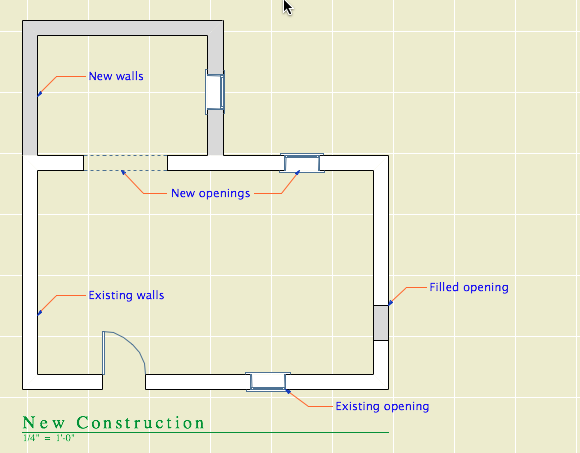
First, to review: The New Construction renovation filter has these settings:
Existing: Override
Demolished: Hide
New: Show
In plan, new walls are gray and existing walls are white. Demolished elements are hidden.
When you demolish an opening in an existing wall, the opening disappears and is replaced by a piece of wall whose status is new.
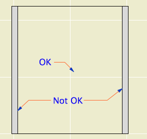
I think this behavior is correct and intuitive. My only quibble is with the lines on either side of the new segment. I'm not convinced the lines should be there at all, and using the cut pen definitely makes them too heavy. But I can overlook it. (Archicad does not consider the difference between element-is-cut and cut-element-meets-air, and I think I have given up waiting for that to change.)
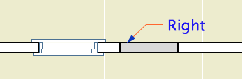
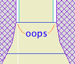
I can't overlook what happens in the elevation. The filled-in portion of wall is explicitly drawn with the shape of the demolished window. There's no way this is OK.
Note: Cut new siding at old window location
• The new wall fragment is based on the existing wall, so it has the same surfaces. Where elements of the same surface meet, the line should disappear. (This is true in AC17. In 16, the material of both sides of the filler piece matches the edge material of the wall. No words.)
• With the surface cleanup rule in place, they would have to create an exception to it, in the belief that it is conventional to show filled-in windows on elevations. We have never done this.
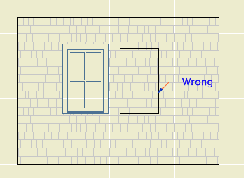
• If I did want to show this condition, it would be dashed and in a lighter pen. These options are not offered. It has nothing to do with the override styles, even though the override setting is what is causing the rectangle to show. The GDL of the demolished window is not involved. The rectangle is drawn with the outline pen of the wall, making it a heavier line weight than the proper windows on the same elevation. Bad graphic, no user control. It couldn't be wronger.
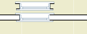
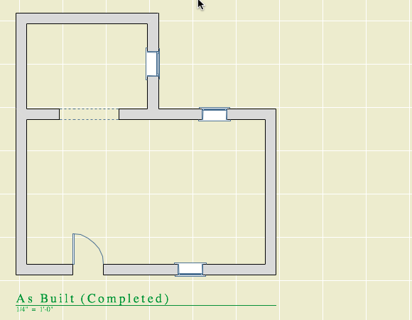
So we need to get rid of it. I stumbled on a way. (N.B.: In the reference guide, there is precisely zero discussion of elevation and hidden line viewpoints in the Renovation section. Once you leave the floor plan you are on your own. Unless you're issuing OpenGL demolition docs, which, um.) In the As Built renovation filter, both existing and new elements are set to show. In the plan, we can't have this because the existing and new look alike. But in the elevation, it means the filled-in wall blends in and there's no rectangle.
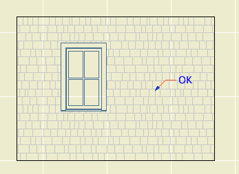
Alright! We just need to use that filter for elevations. Maybe change the name so its purpose is clearer. I don't mind workarounds as long as they work, ya know!
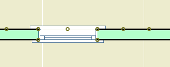
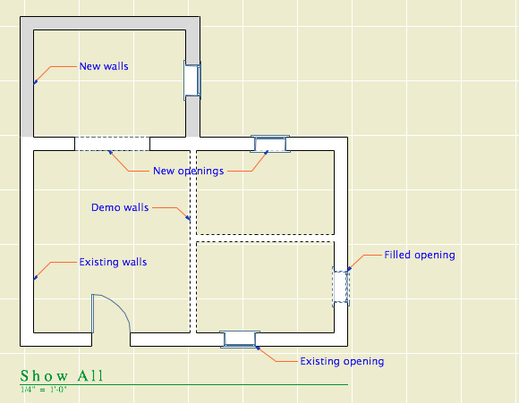
What? Sections? Right, they have cut elements (existing needs to be overridden) and uncut elements (existing needs to match new).
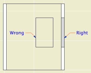
Right like the plan, wrong like the elevation
Good elevation, but we can't tell new from existing
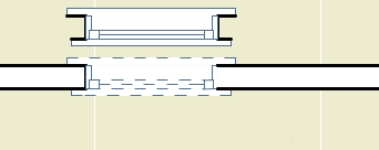
It looks like that filter trick doesn't solve it, and I think we've reached the end of the line. Direct demolition of openings just doesn't work. I don't know how they released this feature in this state, and I don't know how they haven't fixed it three versions later. It's really poor.
We will continue to use renovation. But we have to go back to the old method of splitting the wall on both sides of the opening, demolishing the piece, and filling in manually with a piece of new wall. This works reliably as ever and cleans up in all views.
The logic of renovation is that removing an opening involves creating some wall. When I create a wall to meet another wall and their surfaces match, there is no line. That stupid filled-in chunk should do the same thing.
In situations like this, where a plainly wrong graphic is presented as normal, I get the feeling that Graphisoft's strategy is to hope that conventional documents are swept away very soon by BIMx Docs, live cutting planes, and iPad Pros. My concern for "pens" will seem as quaint as a wax seal! I think they underestimate the status quo bias on the average job site. Today, I need drawings that function in the field. The present is sadly non-futuristic sometimes.
That new world, when it comes, is going to have graphical conventions too, and users will always be charged with turning an ever more complex model into visual information that people can use. At the moment there is a disconnect between the information I can attach to the model ("This window is to be removed"), and the tools to convey that information. ("If this is removed why is it showing?") It should be a core competency of Archicad to bridge that gap.
How to Demolish Openings
First the simple case.
Split the wall at both sides of the opening. The split can be right at the opening's ends, or you can allow some slack.
Drag a copy of the wall with the opening. It's less confusing if you drag it away.
Demolish the opening's wall by switching its renovation status to Demolished. When you demolish a wall, openings in the wall are automatically demolished.
Change the copy's status to New, and delete the opening.
Drag the new wall back in place.
The more complicated case is where a new opening will be placed overlapping the demolished opening. In this situation the pair of walls (demolished and new) must be extended to span both openings, so that the new opening is placed entirely within the new wall.
Placing New Openings in Existing Walls
You do not need to split the wall to place new openings in existing walls. Just place them. The new opening will appear as a demolished portion of wall in the demolition plan. As far as I can tell, there are no graphical problems with using this, the intended technique.
We reviewed some things that people were a little sketchy on.
Which libraries should you use
• The current version's Archicad Library, which is located in the Applications folder, at Graphisoft/Archicad [n]. When you migrate a project to a newer version, you might also pick up an Archicad [n-1] Migration Library.
• The current version's Rill Library, which is located on the Carrot at 2 Libraries/Master LIB [n].
• Do not load the Development library, located within the Master Library folders. Objects in there are in an unreliable state from your point of view. They may vanish or turn into something else without notice.
• Do not load the entire Master LIB folder. That would give the Development folder hazard above, as well as potential duplicates from the Archived Items folder.
• When you migrate a project to a new version, change to the matching version of our Rill library. I do not maintain library parts more than one version back for very long. You will soon be out of date.
• If you have missing or duplicate parts, fix them. You should never see the library loading report.
Here is more on library management and what libraries are where.
Projects need to be on the server
If you take a project file elsewhere to work on it, make sure you put the modified version on the server when you return. If you aren't here and someone else needs to access the project, we need to be confident that it is current.
Where is your drawing list
I have seen cover sheets with no drawing list, and the drawing list box is still titled, "Drawing List". This looks dumb and bad. Drawing lists are generally required by permit authorities, and it is bad user experience not to have them.
Linked detail markers
This is an old, very important, core feature of Archicad. Here is a very old post about it. Nothing has changed.
Here I will re-summarize the detail workflow:
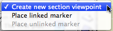
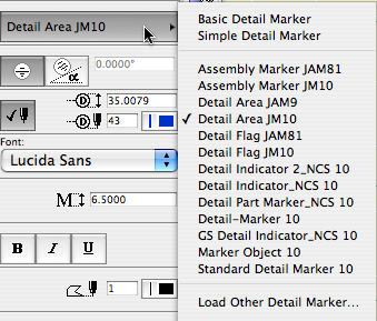
• The default settings of the detail tool in the templates are: create new viewpoint (source marker), in reference to the viewpoint, with the layer +Z SE Hide. To draw details based on other viewpoints' content, use the marker Detail Area JM10.
• Place the new marker with the "Create new detail viewpoint" option. This becomes a source marker. Develop the detail content.
• Save a view of the detail in the CDs/A3 Details/ subset.
• Place the view as a drawing in a layout.
• Return to the detail marker and change the reference to the first placed drawing of the viewpoint. (This is generally robust because there is probably only one drawing instance of that detail.) Change the layer of the marker to +Z SE Print.
• If you need to call out the detail from other locations, drag or copy/paste the marker. The new copies will be linked markers in reference to the selected viewpoint, which is the original detail.
• You can use other detail marker objects to refer to details you have developed using the Detail Area. Those would be placed as linked markers to a selected drawing.
• You can move the detail drawing around the set as you like. If you have to move the drawing to a different sheet, drag it in the navigator rather than cut/pasting it. If you cut or delete the drawing, the markers will go bad.
• To call out any placed drawing, use a linked marker in reference to "the selected drawing".
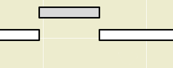
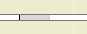
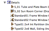
Composite separators should be off for stud walls
For composites representing 2x4 and 2x6 stud walls, the lines showing the drywall and sheathing should be off. At 1/4" scale, they don't read individually and add extra wait to the main wall outline.
• In the composite settings, Use Skin Separator Line should be unchecked.
• In the wall settings, Use Structure's Separator Line should be on.
You Actually Do Have To Split Walls To Demolish Openings
I have much more to say about this.
Keep junk sections junky, and don't have too many
It is very useful to use non-output sections to work on the model. I call these junk sections. They use a simplified marker, a subtle pen color, no names, and IDs of the series x1, x2, ... They are set up in the templates and in the favorites.
Junk sections should never have names like output sections. This makes your Project Map and View Map very confusing. If you have junk sections with real names, fix them.
Never use junk sections for anything important. If you use a junk section to create a detail, or turn one into an output section, then change the pen, marker, and/or name to account for this.
Don't have too many. It is better to have a handful and move them around. Having many sections and elevations will eventually affect file performance. In order to move them around without worry, you need to be confident they are truly junk; see the rules above.
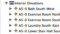
Don't use Up, Down, Left, Right in section or IE output names
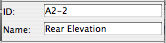
Elevations of the exterior should be called Front, Rear, Left, and Right.
Interior elevations, by default, should be named after the room and the compass direction of the elevated wall. Both of these can be automated if you are using zones (for the name) and have Project North set correctly (for the direction).
Up, Down, Left, and Right refer to the plans, not to the building. It looks odd to see a title like "Kitchen Down"; what is that, the floor?
Interior elevation names can be customized if it makes the title clearer. If there is only one elevation of a room, you can just name it after the room. In the kitchen you can name it after the equipment on that side. At a kitchen island, you name them after the things they face, e.g., "Island Facing Sink". For most walls worth elevating, it is evident what is special about them, and beyond the room name the title doesn't add much. It just shouldn't be confusing.
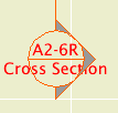
I think the Up, Down, Left, Right idea comes from the IDs we use for building sections. (A2-4R Cross Section looks to the right, A2-4L looks to the left.) These are good, because the help make the name-ID combination unique. But they have nothing to do with output.
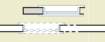
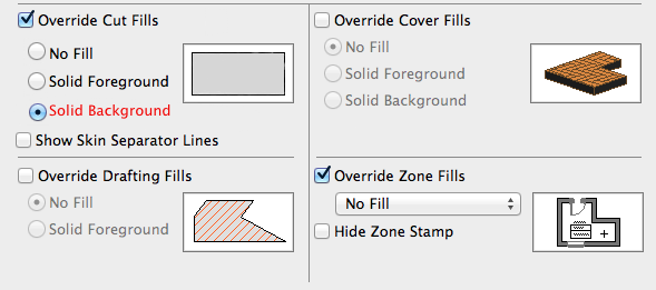
If we had this model view option, it would greatly help the scale-sensitivity problem for composites and profiles. Background only for small scale output, detailed fills at large scales.
I've wanted scale-sensitive composites as long as I can remember. This seems easier? Note the cover fill option right there. Drafting fills too, sure. Consistency.
These guidelines are current as of Archicad 17-18.
Renovation is a feature set to control the display of existing, new, and demolished elements in the workflow of addition and renovation projects. It began in Archicad 15. This feature means we no longer have three of each layer in addition projects.
In the Renovation workflow, there are three kinds of elements: Existing Elements, Elements to be Demolished, and New Elements. This property is the Renovation Status. With a few unimportant exceptions, all elements have a renovation status, and it cannot be blank.
Renovation Filters control whether and how elements of the three statuses are displayed. Filters are saved with Views.
The filters control whether the elements of each status are Shown, Hidden, or Overridden.
I hope showing and hiding are self-explanatory. If elements are overridden, their appearance is controlled by Renovation Override Styles. The attributes covered by the styles are: Line type; Line pen; Fill type, pen, and background pen; and material. There is no consideration for fill category, so cover and cut fills are handled the same. (Fail.) There is only one set of override styles, and they do not vary by filter. (Another fail.) For example, you can't have one filter where overridden demo elements are dashed, and another where they are dense dashed. Whatever the style of overridden demo elements, that's the style for all filters where Demo is overridden.
Because the override styles are responsible for the appearance of overridden elements, elements of different status will have the same "natural" settings. You don't change the line type or fill color of individual elements to show they are demolished.
The styles are set in the template and should be considered set-and-forget.
There are also Additional Filter Options for existing and demolition elements. Right now the only one of these we are using is to turn off markers for doors and windows.
And, keep an eye on it, it will try to mess with you. The current filter can change by viewpoint; it can be new construction in plan and existing conditions in 3D. When this happens, stuff will "disappear". Check the palette. Once the filter is set for a given viewpoint, it seems to stay put. (Both the default filter and the default status seem to sometimes change spontaneously, especially when opening a project on a different machine.)
The status setting is not transferred by eyedropper/syringe. The default setting on the palette always controls. You can change the status of an element in the settings dialog under Tags and Categories, but the palette is obviously easier and a better habit.
Our Override Styles
New elements are never overridden, and have no override style changes. (N.B. This is our decision, not a design limitation of the new status itself.) New elements act as if the filters don't exist. The background pen is gray (#50), same as it ever was.
Existing: The fill is overridden to be Empty Fill. The fill background pen is overridden to be pen 91 (white).
Demolished: The fill and fill background are overridden like existing, and the line type is overridden to be Dense Dashed.
Again, the natural settings of existing and demolished elements are the same as new. The override style turns them white and/or dashed.
See the appendix at the end of this post for examples of the different kinds of output.
Our Renovation Filters
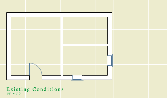
01 Existing Conditions
Existing: Override
Demolished: Show
New: Hide
This is used for building the existing model, and publishing the existing plans and elevations.
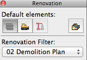
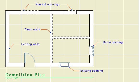
02 Demolition Plans
Existing: Override
Demolished: Override
New: Hide
All the walls have white background, and the demo elements are dashed.
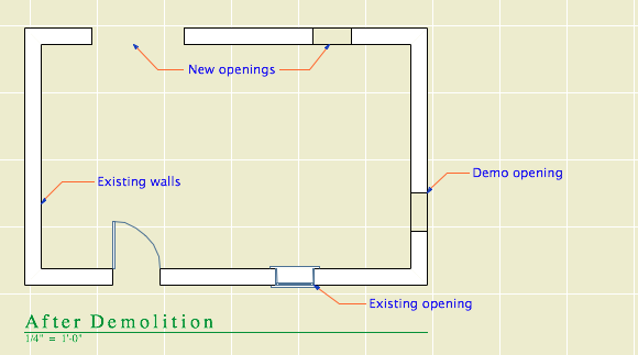
03 After Demolition
Existing: Override
Demolished: Hide
New: Hide
Existing elements only, with the demo elements removed.
04 New Construction
Existing: Override
Demolished: Hide
New: Show
This is used for most work and output. Existing walls are white, new walls are gray.
05 As Built
Existing: Show
Demolished: Hide
New: Show
This shows the project when finished, as if it were all new. All the walls are gray.
06 Show All
Existing: Override
Demolished: Override
New: Show
All statuses are shown, and you can tell the statuses apart.
How to Demolish Things
Select an element and, on the renovation palette, click the demolished button. That changes its status from Existing to Demolished. Unless the current filter is Demolition Plans or Show All, the element will vanish. If you switch to Demolition Plans, the element will reappear with dashed lines.
Demolishing a wall
That's basically it. Of course, you might have to split an element first to demolish only part of it.
The big difference between the new method of demolition and the old layer-based one is in the handling of doors and windows. Doors and windows are now demolished the same way as other elements. Just select them and change their status. There is no need to split the wall and demolish the piece with the opening in it. When you demolish an opening, it is replaced by a portion of new wall. (Note: That new piece is shown using the natural settings of the existing wall. It's no longer being overridden. That's why all elements have the same natural settings.)
Further, you don't need to split an existing wall to place a new opening. Just place it normally (check the status!), and you will have a new-status opening in an existing-status wall. And in the demolition plan, the new opening location will be shown dashed.
Renovation Filters in New Projects
Unlike layers, renovation filters have only one purpose. (There's not going to be any hacking the demolition status to do something else.) If there's no renovating or demolishing, you don't need them. So in the New Home template they are not used. The filters are in there, but they are modified to show all statuses all the time, with no overrides. All the views are set to Show All. The palette can be put away.
Special Cases Where Multiple Layers Are Still Needed
Even on a New Home project there are some sneaky existing conditions, those pertaining to the site. We have separate layers for existing and new topography contours. We have layers for existing, "demo" and new trees. We have an optional layer for backing up the existing site's mesh.
I don't think these things are what renovation filters are for, and I can't see "using" them throughout a New Home project just to address these tiny parts of the project work. So we ignore the filters, and we have a few oddball E and D layers left. To remove a tree, change its layer and enjoy the nostalgic moment.
Don't Demolish Notes, Silly Rabbit
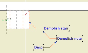
Another layer we didn't delete is +D Demo Note. I have heard of people trying to use one note layer and then make some notes demolition notes by changing their status. This is a category error. Renovation status is for project elements, which represent real things in the world. You're demolishing that note, are you? How? What is the result of demolishing it? Keeping different types of annotation straight is a proper use of layers.
And if we still have the Demo Note layer, we still have the Demo Plan layer combination.
Changes to the Templates
Removed lots of layers.
Implemented renovation filters and override styles.
Applied filters to views.
Updated favorites and default layers.
Created pen set for existing plans.
Secondary Info on Renovation
All element types have a renovation status except hotspots, drawings, figures, and viewpoint-creating tools (Section, etc.).
Elements have a setting in the Tags and Categories division where they can be set to show only on a specific filter, rather than "All Relevant Filters". There's also a button on the renovation palette for this setting. I can't imagine an occasion to use this. That setting is where the warning comes from when you delete a filter: "By deleting a renovation filter, you will lose all elements which are shown only on that specific filter." Since we don't use that setting, we aren't scared of this warning. Further, I don't see the need to delete filters very often.
The filter settings can be imported and exported; they are xml files like Model View Option combinations. (But they import badly, extant filters can't be overwritten.)
There seem to be no GDL globals for renovation status, which seems like a missed opportunity.
As of Archicad 16, sea level is part of the new Project Location dialog box. (Options -> Project Preferences -> Project Location)
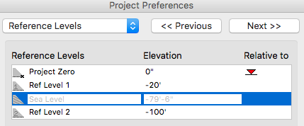
The sea level value is the elevation of project zero in the real world, which is usually the framing floor of the main story of the building (Story 1). This value is entered as a positive number in Project Information.
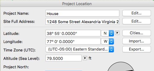
It gets automatically copied as a negative number to the Reference Levels, where it is locked and only for display.
With sea level set correctly, you can build your site model mesh using sea level topo data. Level dimension texts have autotext elements that can refer to sea level. Our standard story level markers and elevation marker objects can refer to sea level or project zero.
If you change the actual elevation of the project, you need to recalculate the sea level value and change it.
Sea level and the other reference levels are only for display and input assistance. Elements are always placed relative to their stories and project zero. If you change sea level, you don't have to worry about your site mesh moving around, even if you used sea level values to set it up.
Intersection priorities help the user control interactions between certain elements. Wall and beam elements have their own intersection priority; I'm calling that the element priority. Composite skins (and components of custom profiles) have their own intersection priorities. Those are skin priorities. Neither of these should be confused with the intersection group number property of layers, though that bears on intersections too!
Element priorities effect plan and 3D geometry. Skin priorities effect only plan. Managing skin priorities is the key to proper automatic joint cleanup between composite walls in plan. Here's a look at the essentials of skin priorities and our standard composite setup.
Update: This method works through Archicad 12, with the key Recent Files. In 13 through 15, it still works, but the key you need to modify is called "Recent Documents". In 16, the Recent Documents key disappeared. Unfortunately I haven't been able to find where the recent documents are stored in 16 and 17.
Also: Under Mavericks (OS X 10.9), the developer of Pref Setter comes up as unidentified, and the current version will not run without modifying security preferences. The old version (I have 1.2.2) will run and seems to work fine.
It may happen that you would like to manually hack Archicad's recent files list. Recent projects are shown in the Start Archicad dialog box when AC launches. Recent projects and library parts are shown at File -> Recent Documents. One good reason to prune this list is that you can get apparent-duplicate items if you open a files from different locations, such as a server v. a local folder. Another reason is if you change servers and you need to make sure the recent items have the right address.
These are OS X instructions. We use the free utility Pref Setter to edit plist files. On Windows, use whatever Windows users use.
The AC preference files are at [home]/Library/Preferences/. There are a number of AC prefs; the one we want is com.graphisoft.AC .plist. You can right-click on the file and choose Open With... Pref Setter, or open the file from Pref Setter's File Menu.
The Pref Setter window will present all the 'Keys' in the plist file. Scroll to Recent Files.
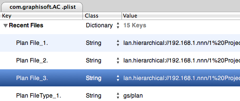
Projects are listed first: Plan File_1., Plan File_2.,... You can delete any of these items. You can also modify the path in the Value field, to point to a different server, for example. Following the projects themselves, there is a Plan FileType_ item for each project. If you are deleting project items, you can delete these items as well, or not. It doesn't matter. Following that is a Plan Number item. This value is set automatically; you can ignore it.
After all the project list information, there is a similar arrangement for recent library parts that have been created or opened for editing. In this context the word 'Symbol' means library part: Symbol File_1., Symbol File_2.,... You can delete or hack these exactly like the project items.
(There are also integer keys for the number of RecentPlans (projects) and RecentObjects (library parts) you would like to see in the list. These are set to 12 by default, perhaps you would like more or fewer.)
We had to do some of this recently when we moved our projects, libraries, modules, etc. to a new server with a different address. When AC launches, it will try to make sure the recent files are accessible. This may lead to a prompt to log in to the missing server. Or, if the password for the server is stored in the user's keychain, the old server volumes can mount without you noticing it. Next comes confusion about where you are actually working, which is never good. Tip: Delete the password to the old server in Keychain Access. That way, you will be notified when AC wants to go looking where it shouldn't and you need to hack your prefs.
(To be honest, even after carefully working through this, I have seen AC mysteriously seek out the old volumes. There's some glitchy behavior going on, but it seems to settle down over time. We do what we can.)
All 3D elements have a User ID, known simply as the 'ID'. It can be observed and edited in the Info Box (near the top in our setup) and in the Settings dialog under the Listing And Labeling division.
The only 2D element with an ID is the Fill.
I wish other 2D elements had IDs. Then I could 'name' topo contours after their elevations.
You can access the ID field of a selected element by typing 'I'.
If the default settings ID ends with a number, the number will increment (increase by one) as elements are placed. Unless you switch off this preference in Preferences -> Miscellaneous. N.B.: The numbers will only cycle through the available numeric places. I.e., ABC9 will be followed by ABC0, but ABC09 will be followed by ABC10.
The default IDs of the tools in your templates should consist of an identifier for the tool (E.g., 'Roof' or 'R') followed by at least two digits, maybe three. This gives the incrementing room to operate.
Other than the automatic increment, Archicad never changes IDs by itself, and there's no problem with elements having identical IDs. (This is different from viewpoints, where the name/ID combination must be unique.) When you drag-copy or multiply an element, the copies will have the same ID as the original. When you eyedropper (alt/opt+click) an element, the ID of the next element will match, but the next one will increment, assuming the switch is on.
The ID is picked up by the eyedropper, but an existing element's ID isn't changed by the syringe.
I keep that Auto-increase preference on, and the only time it bugs me is when I'm placing Shape Tag objects for revisions, and I have to make sure the triangles say 2, 2, 2 instead of 2, 3, 4. (Really, that's just an illustration, because that object has a setting to use a custom text instead of the ID, but using the ID is easier because you edit it directly by typing 'I', bla bla bla)
Letter IDs do not increment, which makes sense now that I think of it. (WALL, WALM, WALN,... that's no good.)
If an element has an error in it, the ID will often appear in the report window warning. This is helpful, because you can use Find and Select to find elements by their ID, then track down the problem from there.
When you're searching for errant elements in this way, you will probably find many of a given ID, because of the drag-copying and eyedroppering described above. To isolate the troublemakers further, you can manage element IDs using a schedule.
We schedule doors and windows by their IDs, and you can change IDs directly within the schedule.
The only element type we deliberately give a blank ID is doors and windows we want to leave out of the schedule. This includes empty openings and weird openings like trim panels.
Zones have the same ID field as other model elements, but we ignore it in favor of the Zone Number field.
The GDL global variable for user ID is GLOB_ID. Elements also have an internal unique ID which is unmodifiable and invisible except in GDL. That global is GLOB_INTGUID. (I promised you trivia.) I can't recall using that one, but you need GLOB_ID all the time for markers and labels.
Somebody asked:
I have finally gotten frustrated enough with the way line types are (dis)organized to focus some effort on it. Have you figured out any tricks to getting line types to show up in any logical sequence at all in your files? I can't believe that after all this time GS hasn't just made it alphabetical. How hard can that be...?
Linetypes are sorted by their internal ID. All attributes (pens, materials, fills, etc.) have an internal ID. This ID is never visible in the general Archicad interface, though it winds up being very important. In settings dialogs, object parameters, and within other attributes (E.g., a composite uses a fill), the ID is what matters, not the name. The only place you can view and (sort of) manipulate IDs in in the Attribute Manager.
The other attribute types sort alphabetically in their lists, but for some reason linetypes don't. There's no excuse for this from the user's perspective, but you've probably noticed it's not the only charming eccentricity of AC's interface.
If you want the linetypes list to sort in a predictable way, you will need to hack their IDs. This is both a pain in the chair and not entirely free of risk.
If you change the geometry and/or name of the linetype at ID #4, all placed instances of linetype #4 in the project will change. If library objects have linetype #4 in their default parameters, suddenly they will have new defaults in those linetype parameters. Elements only care about IDs. Modifying libraries to adapt to such a change is prohibitive. Where the Archicad library is concerned, it's practically impossible because it's bad form to modify it at all. And, if you modify your own library, you have to be wary of affecting past projects going back however far, should you ever reopen them.
I did try to sort my linetypes a few years back. I survived, because we don't actually use very many, and I did some investigation to see what linetypes the AC library cares about. There is compromise involved. Our primary dashed line is at ID #2, but the AC library expects a dashed line at ID #4. If I put something else at ID #4, AC objects will display that instead of a dashed line. If I delete ID #4, those objects will have a missing linetype, which renders as solid, same problem. Meanwhile I can't abandon ID #2 because my libraries are hooked to that. So I'm stuck with two dashed linetypes at the top of my list, nothing I can do.
One more thing: If you do whip your list into shape, it will still be two lists, with the symbolic types following the vector types. Like symbolic and vector fills, that sorting can't be hacked.
As for how hard it might be for GS to fix this sort of thing, well, empirically it looks impossible. Hope to proved wrong.
Autogroup: On
Hide locked layers: Yes
Pet Palette movement: Jump
Tracker: Off
Coordinate Box: On
XY Button: Up
RA Button: Down
Move the origin a lot: Yes
Do that thing where you rest the cursor on a point and enter distances followed by + or -: No
Magnet: On
Info Box: Vertical
Navigator Preview: Off
Quick Layers: Off (Toolbar buttons)
Surface highlight selection: On
Contour highlight selection: Off
Info Tag: On, 100 second delay
I guess Autogroup isn't really an interface thing.
Or, seen and not seen. Fills, white pens, and materials.
The user has requirements. The software has capabilities. Where the capabilities end and the requirements keep going is a limit. To get beyond the limit requires workarounds. Some limits are harder than others and all we can do is wish (beg) them removed.
Here's a rich example concerning structural posts (columns) in residential construction. These are things like 4x4s, multiple 2x_s, steel pipe columns, tube (TS) shapes, and the occasional W shape placed vertically. Hard limits in Archicad are in bold. Stuff I've figured out is the rest of it.
A reference marker is a special object that can intelligently refer to viewpoints within the project or drawings placed on layouts. They also create viewpoints, which is a strange kind of double duty. Then you can also create viewpoints without markers... it's not intuitive overall. For most cases, you can think of a viewpoint as an application window. Sections, elevations, interior elevations, details, and worksheets are all viewpoints. So are schedules and even stories, but they are not related to the marker discussion in the same way. Everything in here applies equally to sections, elevations, and details.
A source marker creates a viewpoint. It is the viewpoint, in a manner of speaking. If you delete a source marker, you delete the viewpoint. If you copy a source marker, a new, additional viewpoint is created.
A linked marker is more like an object, though still a special one. When you place a linked marker, no viewpoint is created; the marker points to something. Any number of linked markers can point to a particular viewpoint or drawing. They are just pointers, and they can be created or destroyed without affecting anything else.
Both source and linked markers can refer to drawings.
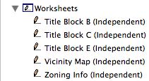
You can have a viewpoint with no marker. Such a viewpoint is independent. You will very often have independent details. At this time all of our worksheets are independent. You can even have independent sections and elevations, but I don't see any advantage to these. Interior elevations can't be independent.
Choosing Source or Linked
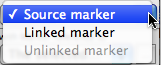
When you get ready to place a marker, whether to draw a new section or refer to an existing detail, you will see these choices in the info box:
When you select a marker, the options look like this:
You can turn a source marker into a linked marker and vice versa, but don't. It's complicated, potentially destructive, and I'm pretty sure it's silly. Treat your viewpoints as 'real' things, and use linked markers to point to drawings in any way you like.
With Marker reference to
In practice, a linked marker should always refer to a drawing. It makes for a smoother workflow if you place the drawing in the layout before placing linked markers.
When you choose to refer to the drawing rather than the viewpoint, you have three choices.
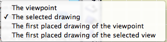
• The selected drawing lets you choose the drawing manually from the layout tree.
• The first placed drawing of the viewpoint means you don't have to choose the drawing. The marker will find the first drawing of that viewpoint in the set and refer to that. You can choose this option before the drawing is placed. If you go this route, make sure the first drawing is the only drawing, or you are sure the first one is the one you want. N.B.: In our layout tree, the schematics sub-book comes before the CDs, so this 'first' thing will always use a schematic elevation instead of the same elevation in the CDs.
• Similarly, the first drawing of the selected view lets you name a view in advance of placing any drawing. When the drawing is placed in due time, the marker will refer to it. This 'first' method is safer, because 'view' is more specific than 'viewpoint'. For example, the schematics and CDs use different views.
With a source marker, you can only choose a viewpoint, view, or drawing associated with the marker's viewpoint. A linked marker can point to anything.
Warnings about deleting markers
When you have a source marker selected and you strike delete, you will get a warning to the effect that deleting a source marker will also delete that marker's viewpoint, unless you choose to keep it as independent. If you confirm that you want to delete the viewpoint along with the marker, you be warned again, to the effect that deleting sections (e.g.) is not undoable. This second warning is as old as the section tool itself, and you know what it means.
If you delete a viewpoint from the Project Map, you will only get the warning about undoability. When a viewpoint is deleted in this way, its source marker and any linked markers are automatically deleted.
When you delete a linked marker, you don't get a warning, because nothing important or non-undoable is happening.
The MVO dialog has three divisions. Options for Construction Elements concerns the display of real things, including openings, columns, beams, and markers. Options for Fills and Zones concerns how different categories of fills are displayed; turning cover fills on and off, e.g. Options for GDL Objects has only one item at the moment, the beloved Story Viewpoint Type, also known as the ceiling switch.
The keyboard shortcut to open the dialog is Cmd+9. I think the MVO dialog is pretty good about previewing the effects of most of the controls.
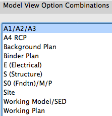
Rather than describe each combination, or heaven forbid build a table, I'll describe the A1/A2/A3 combination, then how the others differ.
Isn't north up? Probably not. Since the orientation of the project is driven by the geometry of the plan, north can be any which way.
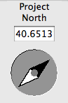
In the Sun dialog
Note: Though it's called 'Project' north, it's true north, in that it's the only north, and the north used by the sun settings. Archicad doesn't directly support a project north environment variable separate from true north.
There are at least four reasons to set project north correctly:
• Accurate sun shadows
• Automatic orientation of north arrow symbol objects.
• Automatic dimensioning of metes and bounds using the Survey Dim RND9 object.
• Correct naming of interior elevations with the Orientation autotext. (A real project north would be nice here.)
For the purposes of sun shadows and interior elevation names, you can eyeball the north direction by moving the pointer in the Sun dialog. A degree or two off isn't going to hurt.
For the metes and bounds to work, you need to set the direction exactly.
Every viewpoint has a name and an ID. The name is important and is often used for output. The ID is never used for output, but wherever possible we use the ID to help organize the project map and view map.
The behavior of IDs varies among the viewpoint types, so here's a cheat sheet.
The primary Schedules have an ID to sort them to the top of the menus. Incidental schedules don't need IDs. This may change.
Cameras and paths have unique IDs that can't be changed.
Summary: Viewpoint IDs are not used for output, so use them to help sort the lists. Names are used for output: Use the name you want to see on the paper.
The IDs that do matter for output are those of the layout book items; subsets, layouts, and drawings.
Drawing IDs are usually generated by the layout, either by the grid or the order of drawings in the layout book tree.
Layout IDs are usually generated by the subset.
Subset IDs are set by the user, and the subset ID becomes part of the layout ID.
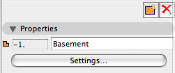
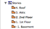
Views also have IDs, but they should typically inherit the viewpoints' IDs, so the lists will appear the same to us. All view IDs can be customized or set to 'None', but you can usually just leave them be. In the templates, I have deleted all the IDs for story (plan) views, because stuff like "-1. Basement" looks idiotic.
Somebody asked why the flue object can't show a thickness for the flue liner itself.
The other reason: The flue is designed with SEOs in mind. You have to use it as a subtraction operator, or there's no point. It is a simple solid tube (EXTRUDE, actually) which we use to make a simple void. If the flue wall has a thickness, it becomes a solid ring with nothing in the middle.
Well, I could wireframe the layer in building section combinations and make it solid in wall section, and I could make the thickness option scale sensitive in the flue and the smoke chamber, but we're into serious inelegance now. It's a void, except when it's not and it's simulating a void, and it's scale- and layer combination-dependent, and do I 'really' subtract it to 'simulate' a void, I can't remember.
Once again we have met a limit in GDL object technology where the simplest solution is for Graphisoft to give us more power. There is a directive, MODEL, which allows you to build shapes in wireframe or surfaces-only mode in addition to the default, normal, solid mode. MODEL WIRE makes a wireframe shape that looks exactly like switching a layer to wireframe. MODEL SURFACE makes a shape that looks normal from the outside but is hollow. This sounds promising for our problem until we realize that only MODEL SOLID shapes can act as SEO operators.
Therefore, I want a new MODEL option which will make shapes wireframe, but which will allow the shapes to act as operators. So the flue wall would subtract, and the void within the flue would subtract, but the void would still be a void. My first stab at a name is MODEL OPERATOR, but I'm open to suggestions.
The Drawing Manager appeared in Archicad 10, taking the place of Drawing Usage in PlotMaker 9. You can open it by clicking the button at the upper left of the Navigator.
It lists every drawing placed in the project, displays various settings of the drawings, and offers tools for performing drawing-related tasks such as updating, changing the linked view, breaking links, and changing drawing element settings.
You can perform most of these tasks elsewhere on a drawing-by-drawing basis by right-clicking on a drawing element, or on a drawing item in the layout book tree. But Drawing Manager offers you a power-editing mode where you can modify many drawings at once. Examples:
• Update all the manual-update drawings.
• Change all the instances of a drawing title to a different object.
• Make all of one kind of plan use a new, specialized pen set.
The key to these mass-modifications is to organize the list by the various properties, by clicking on the column headings. There is similar functionality in the Finder and many other programs.
For example, to update all the Manual Update items, click on the Update Type column, highlight the Manual ones, then click the update button.
For another example, sort by Drawing Title to change all the Drawing Title JM10 to Drawing Title JAM10a.
Etc.
In Archicad 11 they didn't change the Drawing Manager much, but they did change the way you choose what columns to display. In honor of the occasion I thought I should point out which columns are most valuable and which you should leave off.
Columns can be resized by clicking and dragging on the joint between two headings.
If you look closely at the headings you'll see that one has a triangle and another has two triangles. The one is the last column you clicked, and the two is the previous click. This gives a two-level organization where the list is sorted by the last criteria, and within that, by the previous one.
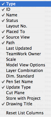
These columns should be on:
• Type. Plan, section, external file, etc.
• ID. Of the drawing in its layout. Not critical, but it's little.
• Name. Of the drawing, which will usually be the name of the view that created it.
• Placed To. Name of the layout where the drawing is. (Usually a layout. Drawings can be placed in model windows, as you might a DWG. In this case that window would be listed here.)
• Source View. Name of the view from the view map, actually the whole path, including the stupid '/Residence' or '/Addition' notation. This is the kind of half-baked design decision you make when you develop primarily on Windows.
• Path. If it's an external drawing. Otherwise it says 'Internal'.
• Pen Set Name. Pen set assigned to drawing element. All drawings need a pen set.
• Update Type. Automatic or manual.
• Drawing Title. Object name of the automatic marker, if it's in use. Plans, among others, don't use automatic titles, so this field would be blank.
What? I know how to open a file! Jeez!
OK. Just in case:
Always open AC files via right click -> Open With or by dragging the file to requisite AC icon on the dock. I do the dock thing; I'm just not a context menu person usually.
Most important, don't double-click PLNs. Double-clicking will only give consistent, predictable results if you have exactly one copy of AC on your machine.
When you install a new version of AC, as you soon will in the form of 11, that version becomes the default application for opening PLNs. So you double-click your AC10 project, it opens in 11, you don't notice the difference because there isn't much, you save it, and next time you try to open it in 10 it doesn't work. (Yes, backsave. Real convenient.)
Always keep current versions of AC on the dock. Even if you use the right-click method, the dock gives you visual confirmation that the right application is being used.
Graphisoft gives poor support in this area, by making the icons identical and naming each version, precisely, "Archicad".
Double-clicking files is one of those 'automatic' things that's great if you can trust it, but when it's not predictable it makes trouble. It's not just AC either, recently my .docs started opening in Pages for some reason.
What about that 'Change All' under Open With in the Get Info window? That fixed my .doc issue, but it doesn't reliably assign the right 'Archicad' version.
So, right-click or dock. If you have a bad habit here, change it now before 11 starts getting on your nerves.
Update re app icons: Mr. Briggs to the rescue.
Summary: With the model and the layouts in one file, pen sets manage the difference between the model pens and the output pens. In addition, they can do view-option-type tricks.
Background: In Archicad 9, there was one set of pens. In PlotMaker 9, there was also only one, and it could be different from the set in AC. Or, each drawing could have its own pens, but it was impractical.
Our standard has always been to use a colorful set of pens for modeling, which translates into a black/white/gray set of pens in layouts. We are far from unique in this arrangement.
In 10, they threw PM into the abyss, so they needed a method to maintain at least those two groups of pens within the new unified project file. So, Pen Sets.


It is allegedly faster to load the libraries as a single large file than from folders full of folders full of individual objects. But I must say in my informal testing I haven't observed a dramatic difference among loading library folders, PLAs, and LCFs.
In addition, there's at least one characteristic of LCFs (and archives) that is disadvantageous. You can't save objects into them. So no new objects and no editing. (You could view this as an advantage from a standards point of view; nobody can mess anything up.)
In other words I considered using an LCF for the Rill & Decker Standard LIB but decided against it. There's no change in everyday library management.
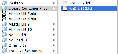
But! There's a huge advantage to the LCF in one specific case: Copying libraries to a flash drive to take them home. The R&D library is about 15MB. Copying its 1300 or so items to a USB 2.0 drive takes over two minutes. Copying the same library as a 15MB LCF takes, drum roll, three seconds.
It also takes the guesswork or other syncing strategies out of keeping your home copy of the library up to date. Just bring the LCF home and overwrite the old file.
So I'm providing the library as an LCF for this purpose. The file lives at 2 Libraries / Library Container Files. I will do my best to update it when anything important changes. This is pretty often, so make sure you check it regularly.
You still need to manage project libraries manually.
In Archicad 10, sections can automatically show story level markers and lines. They are feature-limited but I think they're worth using.
The browser interface of the object tool etc allows the library person (me) to gracefully deprecate old objects, and steer users toward the good ones.
When we update an object, we move the old one to the xOld R&D folder. This folder loads, so placed instances of old objects will continue to work. The updated one is the only one visible in the proper folder, so there's no question about which one is right. There's a Center Line symbol, it's in Graphic Symbols, and that's it.
Can't do it with markers. The marker chooser makes things more confusing than they need to be. For example, on the detail marker list, three out of thirteen items are meant to be used.
In which I tilt at the windmill of Floor Plan Cut Plane, Relative Floor Plan Range, Automatic show-on-story, projection... It's not pretty. I mean, it's so pretty! You should read it!
This is some of the stuff I was keeping from you when we discussed roofs in plan.
Fill display is confusing and inconsistent. Until it gets tidied up, this is all I can tell you.
By default, favorites remember all the settings of the tool. You can choose to have favorites ignore certain settings; when a favorite is applied, those settings will be unchanged. This is called parameter exclusion. It is one of the favorites preferences, which you get to via the flyout at the upper right of the favorites palette.
Only a handful of parameters can be excluded. The exclusions are global: If wall height is excluded, it's ignored by all the wall favorites.
The exclusions, like the favorites, are stored in the file; but exclusions are not imported when you load favorites. (Or maybe they're not saved. Makes no difference in the end.)
This is a summary of the exclusions in our template:
• All elements: ID
• Wall & column: Height
• Section/Elevation: Name
To put it another way, these are the things that are allowed to vary as the favorite sets everything else.
Remember, favorites are nice, but option-clicking is often best. To make an element exactly like another, always option-click.
(Favorites have improved in the three years since I first addressed them, so the post should improve too.)
Favorites are preset configurations of the tools. They enable you to quickly configure a tool for a given purpose, like option-clicking without the need for a placed element.
There are three main ways to create views in AC10, plus one more you should never use. The templates have most of the commonly needed views already set up, but it's not unusual to need more.
Update, November 2017, Archicad 21: These screenshots are out of date, but all the principles and operations remain the same.
The model is in there. Don't look at it, just imagine it. Think of the real buildings you can't see at the moment. The Lincoln Memorial is there. Trust me.
The model is before everything in the Navigator. No model, nothing to Navigate, right?
The Navigator, besides being indispensable to your productivity, is good illustration of Archicad's intended model-to-deliverables workflow.
Update: Buttons look different starting with Archicad 20.
Archicad 10 finally gives us the ability to place PDF files in layouts, as well as other project windows.
PDF-in-layout will become the standard method of placing non-Archicad info in drawing sets. Any file (Word doc, spreadsheet, etc.) can be saved as a PDF via OS X's Print PDF facility. In the current templates, the abbreviations and general notes are PDFs. It's the new stickyback.
Since you can place PDFs as model windows too, you may find it more convenient to use PDFs for topo surveys, plats, and the like.
PDFs become drawing elements. Since drawings are polygons, you can crop the PDF however you like with the pet palette.
There are several methods for placing PDFs, in rough order of convenience:
• Drag the PDF file from the Finder into the Archicad window.
• Use the Drawing tool. Click where you want the file to land.
In a layout window, you get the 'Place Drawing' dialog. Choose 'External Source' and then 'Browse'. Navigate to the file you want.
In a model window, you can only place an external drawing, so you immediately get the Open dialog, where you can choose the file.
• File -> External Content -> Place External Drawing. Select the drawing in the dialog box. (Least convenient method IMO.)
Whatever method you use, you can only place one page of a PDF at a time. If the PDF has multiple pages, you will get a dialog box where you can choose the correct page. To place multiple pages requires multiple drawing elements.
Since they're drawings, they can have titles, but they usually shouldn't, right? Make sure the title is set to 'None'.
Like all external drawings, PDFs will be Manual Update by default. If you modify or re-save the PDF, remember to update the drawing. I don't recommend setting external drawings to Auto Update.
If you take the project file off the network (home, e.g.), you will get a warning that the source file for the PDF can't be found. This is usually not a problem. The drawing will still appear, you just can't update it. When the project is reunited with the network, the warning will go away, and you can update the drawing as needed. (Note the similarity to Hotlinked Module behavior.)
I've taken another stab at standardizing the Work Environment. This for AC10 only.
The Active Layer palette is accessed on a submenu of the Layers submenu, which might be on Options (9) or Document (10) or somewhere else by now. You mean the Quick Layers palette? No. Active Layer.
This palette does exactly one thing, and I use it for exactly one purpose. It switches between the default state of 'Individually Set Layers' and the weird state of 'One Active Layer for al Element Types'. That is, it can set all the tools to the same layer in one go. And it can put them all back to the layers they had.
No, I wouldn't want all the tools on one layer, ever. I don't know why they made this thing, but here's what it's good for. Attribute Manager will report that a layer is in use if it is the current default of a tool. So you can't really tell if an element is on the layer or not.
So, use Active Layer to set all the tools to the Archicad layer. Set the palette to 'One Layer' and then set any tool to the Archicad layer.
(The other source of phony checkmarks in Attribute Manager is Favorites.)
When you close the Active Layer palette, or close a project where all the tools are 'One Layer', you'll get a dialog asking if you want to keep the One Layer, or Revert to the individual layers. You should choose Revert. (Of course, if you've deleted most of the layers, there's nothing to revert to, but it doesn't matter.)
It is not possible to delete the entire Favorite list at one time. You can only delete them one at a time, which, if you have a lot, no thanks.
But you can write over the entire Favorites list with another list. If this list happened to have, say, one item on it, well that would be pretty easy to delete.
We have the Favorites file 'Blank.prf' for this purpose. It resides at 3 Resources / AC / Favorites. It consists of a Favorite for the Hotspot tool, Archicad layer, pen 10, that's it.
On the flyout on the Favorites palette, choose 'Load Favorites', and open the Blank.prf file. You will get a dialog offering to merge or replace the current list. You want to replace. (Merge adds the new list to the old.)
Delete that hotspot fave and you've got your blank slate.
Why delete the Favorites? It helps clean out attributes. Attribute Manager will report that an attribute is in use if it is part of a Favorite. With no Favorites, it's one less place to look before you're sure you can delete something.
And of course you can clear them temporarily. Save the Favorites you are using, clear them, do whatever you need to do, then load your saved list back.
Every attribute (pen, fill, linetype, layer, etc) in AC has a unique ID number. Internally, AC handles attributes by their IDs. The names are just for us. The IDs control the interactions between attributes, and the default parameters of objects. When a composite or material has the wrong fill, or an object comes in with a surprising default setting, it's often because IDs have become tangled up.
They don't get tangled up on their own, but it seems like they do, as we create and delete attributes, merge them from other projects, etc. Attribute Manager gives us some ability to manipulate IDs, but it's tricky.
Here's an example of the gymnastics you need in order to work with the antiquated attribute ID system. On the other hand, at least it's feasible. On the final hand, it is unbelievable that we can't edit IDs directly, and really we shouldn't have to interact with them at all.
It's also a good example of how attribute IDs can mess things up, which is why you have to hack them.
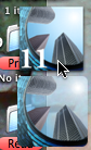
In this case, all the openings in the Archicad library default to drawing their overhead lines with linetype ID 4. In the templates that ship with AC, that ID is a dashed line, which is fine. In our templates, ID 4 is the 'Layout' linetype, a dot and dashed thing. So unless you change it, the openings look like this:
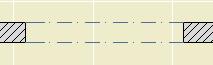
Errrrrrg.
Moral: Generally speaking, attribute IDs are strong and attribute names are weak. AC only cares about the '4', not the name 'Dashed', and not the dashes themselves.
The other moral: Especially where libraries are concerned, it's best not to fight default IDs if you can avoid it. It's better to fix one linetype rather than a whole pile of objects. That's where the gymnastics come in.
The Element Information palette is accessed at Window -> Palettes -> Element Information. It's a palette; it will hang around until you dismiss it, like Find & Select or the solid elements thing, whatever ridiculous name it has.
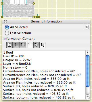
There are six sections of data, each activated by one of the buttons. Any or all of the buttons can be active at once. They are:
Properties: ID, layer, and story. This is the only place you can directly read the home story of an element. I don't know why this has to be such a secret.
Size: 2D dimensions. Lengths, widths, and/or 'circumference', which we would expect to be called 'perimeter'. Use fills and this info to do that new/existing comparison the permit people want sometimes.
Area on Plan: 2D Area. Self-explanatory, but note that it's different from the 3D surface area, which is coming up.
Height: Pretty obvious for most things. For roofs, it also gives the perimeter I mean circumference of the top surface. For walls, conventional roof trimming is not considered.
Surfaces: Areas of all the 3D surfaces. Note: Solid Element Ops are taken into account.
Volume: What it says. SEOs work here too. I have actually used this for a back-of-envelope cut/fill grading calculation.
This isn't really calculation, it's just inspection. To actually do anything with the data, besides write it down or copy and paste it, requires list schemes.
Here is the Graphisoft product page.
Here's a short feature list. It reflects my personal biases. Things they are really excited about, I might not even mention!
• PlotMaker is no longer with us. Layouts are part of the project. For large projects, it might be advisable to have the model and layouts in separate files, but they would both be PLNs.
• There is a cutting plane associated with each story, which can be used to automatically display roofs, and other elements, with their true relationship to the current story.
• You can create custom profiles for walls, beams, and columns. I'm not so excited about the beams and columns, since they have no parametrics, but the walls have a lot of potential.
• Interactive Schedules have finally reached version 2. They are greatly improved, and we will use them more and more. Most exciting: Automatic drawing lists.
• PDFs can be placed in layouts.
It is slated for release in the first week of May.
We will not rush into this one. As of this writing, I do not plan on migrating projects. That is, if you started in 9, you should finish in 9. And, I don't have templates for 10 yet. So you can't start new projects in 10 either.
10 is a worthwhile upgrade. But it will be quite different, especially in the documentation area. AC9, and our AC9 methods, are very reliable and not to be abandoned lightly.
Archicad is designed to automatically save project data periodically. In the event of an AC or system crash, project data can usually be recovered. AutoSave is described on page 150 of the AC9 Reference Guide.
Yes, it's a little late for a New in 9 post, but that's what happens when I pretend I'm going to tell you, briefly, anything meaningful about something as gigantic as a rendering engine. After all, it's the sort of thing people write books about.
Said book, by Dwight Atkinson, Canada's funniest Lightworks in Archicad expert, is in the possession of Rill & Decker, or maybe me personally. So if you want to have a look, be my guest.
If you UNCHECK 'Use Cut Elements' Section Pens' in a section's settings, all the cut lines are drawn with one pen, and all the fill patterns are drawn with one pen. The background color becomes clear.
I usually want this box checked, so the distinctive section pens of elements can be seen, which aids model organization and usability. For wall sections, I think there are a couple of advantages to letting the marker set the section pens:
• Model elements can be transparent while fills still have opaque backgrounds. So I can mask stone veneer with a CMU fill, without using two fills. Under the current standard, the Fill Background Color Display Option is set to Transparent, which effects model elements and fills.
• Following from above, the A3 Display Option Combination could be eliminated.
• If you use black (15/11) pens for the section and color pens for added 2D work, it's easier to tell which is which. (Note: Elevation pens are unchanged.)
• I recommend a 5-weight pen for cut lines, unless the element is very thin; e.g., a counter. Using a thinner pen for the section looks better at 1/4" scale, but at 3/4" or 1" it looks weak. With uniform pens, you could have it both ways.
But I don't think we can do it. Certain objects, most prominently Wood Beam JAM9, have clever pen-related section behavior, which the uniform pen feature breaks. This is the wood beam at wall section scale; it knows to draw the X lighter:
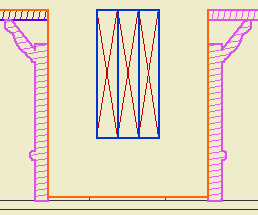
But the uniformity heavies up the X along with everything else:
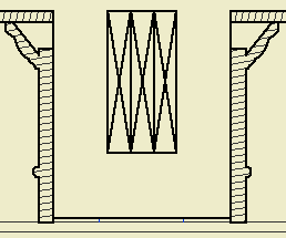
Which is no good, and it really can't be fixed without patches or conversion to drawing, so what's the point. You can always make a line heavier by drawing over it; lighter, not so much.
The technique might be beneficial for interior elevations, since it turns the gray background off. And interior elevations don't show structure members. We should look into it.
Hotlinked Modules are another Big Feature I can't describe fully before moving on to giving you the derivative techniques. There are several English/Hungarian bilingual people whose job it is to fully describe to AC interface so I don't have to. Their efforts can be appreciated starting on page 421 of the reference guide.
Again, I'll just hit the high points.
Hotlinked modules are external project data placed in a project. In the host project they are treated as a single, uneditable group, with hollow, square nodes. They can't be edited directly in the project where they are placed. They have to be opened separately. This is a good occasion for running two copies of AC. Hotlinked modules are one story at a time of solo projects, teamwork projects, or module files. (There is an annoying overlap of meaning between hotlinked modules and .MOD files.) You can place multiple stories of a project, but each is its own module, placed individually.
The default behavior is for AC to check hotlinked modules for changes when the project is opened. You can change this, but don't. You can also do a manual update using the Hotlink Manager. Changes in modules are reflected in the project once the update is complete.
The Hotlink Manager is at File -> Modules and XREFs -> Hotlink Manager. It is here that modules are placed, updated, broken (turned into local, editable elements), and changed.
Breaking a module results in one big group. If you ungroup this group, you will get the groups within, as they were in the original file.
Modules can be mirrored, elevated, and rotated. When a module is rotated, zone stamps and text blocks can rotate themselves to compensate.
Placing a module is completely different from merging a module file. When you merge, the elements become part of the project. Hotlinking is an ongoing external reference.
Only Archicad files can be hotlinked. If you're placing DWGs, you need XREFs.
Applications to follow. Including:
Accessory structure alternates.
Energy calculations.
Showing a rotated garage level on the layout.
Note: Schedules in AC10 are completely different.
In here, where you can't see them, I have drafts of posts. The list of drafts can be viewed as the to-do list for the site. Stuff I know I have to tell you about, but I haven't gotten around to actually doing it. Many of the drafts relate to features of AC that are very powerful and proportionately complex. I don't want to regurgitate the reference guide, but I don't want to merely point you at the reference guide either. So there they sit. Since we're talking about powerful features, naturally there are other drafts of specific tips which have as prerequisites knowledge of the powerful features.
Anyway it's more important that you have the specific tips than the admirably balanced non-regurguitated, non-merely-pointing-you master post. Between the tips and the reference guide, you'll get the big picture. I hope.
One of these features is the Interactive Schedule (IS). We even had a meeting about it, since it's a lot easier to show and tell than to describe in text. I use the IS for door and window schedules, finish schedules, area calculations, and energy calculations. I also use is as a hack Find & Select for parameters within an object, so you can find all the crown elements that use WM-47 and change them to SM-28. Chances are some of these methods interest you, and I think they should, and I've been stalled in documenting them by the intimidating difficulty of the master post, which you'd think from the title would be this one.
So. The IS is documented in the reference guide beginning on page 374. Consider yourself pointed.
The ref guide does OK at telling you what the IS can do, but I think it's still up to me to point out its limitations. It is still very much a 1.0 feature.
• It only works in plan.
• It is modal, that is, you have to dismiss it in order to work in any other window, unlike, e.g., the Find & Select box.
• It can't do math beyond adding a column of numbers. No way to reduce an area by a percentage, e.g.
• The method for sharing schedule settings between projects is pathetic.
• It has too many poor interface quirks to list here.
It does what it does. In the future it will do more, and it's already way more accessible than the rest of the calculate menu.
More to follow.
PS, another big one is Hotlinked Modules. You need those for the energy calc thing I mentioned above. Sigh.
As of, I don't know, 8.1, Display Options can be organized into Combinations, kind of like layers, and Display Options can be saved with views. Our templates have been set up this way for some time, but I don't think I've ever cataloged the combinations. They're just as standardized as anything else. Highly.
In the DO dialog, there are two panes, Display Only and Display & Output.
The Display Only options do not vary among combinations. Real quick: Intersections are on, Walls are contour lines, all the handles are on, section depths, detail boundaries, and markup elements (never used 'em) are hidden.
Display & Output options is where the action is. Rather than describe each combination, or heaven forbid build a table, I'll describe the A1/A2 combination, then how the others differ.
In A1/A2, which gets saved with plans and elevations for output: Beams are Contour Lines (no reference lines), Line Weight is Hairlines (they get turned True in PM), all the Fills are Vectorial, Doors & Windows Show with Dim, Zone Polygons are None, Zone Stamps Show, Section Markers are As in Settings, Column Symbols Show, Fill Background Color is By Element Setting.
Working Plan/SED is the same as A1/A2 except Beams are Entire Beam (ref lines on), and the Drafting and Cover Fills are Bitmap.
A3, which gets saved with wall sections, is the same as A1/A2 except the Fill Background Color is Transparent. (This means no fill backgrounds. Use Solid Fill for white masks. To mask with a pattern fill, you need two overlapping fill elements.)
A4/S0/M/P, which gets saved with RCPs, mechanical, plumbing, and foundation plans, is the same as A1/A2 except the Doors & Windows are Reflected Ceiling.
S, which gets saved with framing plans, is the same as A4/S0/M/P except the Cut Fills are Separators only. This turns the wall fills off, but shows a line at the joint between, e.g., concrete and stone. Fill backgrounds are on, so masking fills will work.
Site, which gets saved with site plans, is the same as A4/S0/M/P except the Cut Fills are No Fills. You will only see the effect of this if you show walls on the site plan.
A quirk of DO Combination management: You can't rename them. You have to Save As, which leaves the old one in place, and then you have to redefine the views that use the renamed combination. Then you can delete the old-named one. Also, I haven't figured out how to import DO combinations from other projects.
UPDATE: Better info here.
Suddenly, Richard's AC could not open a file on the network, and would hang (rainbow ball of death) when attempting to browse a network resource, such as the Hotel. We noticed it when attempting to open another project in Attribute Manager; since the previous state of that Open dialog was viewing the Onion, hang.
All conventional treatments exhausted, I had to call tech support. They directed me to this knowledge base article, which has to with switching off a cross-platform browsing preference that we don't need anyway.
If you ever see this behavior in AC, here's the fix.
Make sure AC is not running. Open Terminal (Applications : Utilities : Terminal). Paste this text into the window and strike enter:
defaults write com.graphisoft.AC\ 9.0.0\ USA\ v1 InputOutput -dict "DisableCrossPlatformMountingFeatures" "<true/>"
That's it. Quit Terminal and relaunch AC.
If you drag a dimension string, the texts will re-center themselves on their segments, assuming the texts have not been moved manually.
You don't actually have to drag the string anywhere, just a drag and a double-click will do it.
The only way a dim text would be off center without you moving it is if you customized the text.
Who cares? You, because you probably changed some texts to read EQ or something, and re-centering them by hand is a cumulative chore.
So, after changing the texts to read whatever, (deselect the texts,) select the string, Cmd+D, clickclick. Note: if the dimension tool is active (very likely), you have to do a Drag command; cursor-drag will edit the witness line length. You can drag with the arrow tool and it works; I think the Cmd+D method is better since you don't have to be precise. Any texts that you moved manually will stay put. AC remembers which those are.
I just dimensioned all the Vassos ceiling lights on the electrical plan, which, if you've never had the pleasure, boils down to a LOT of EQ EQ EQ EQ EQ. So I was really happy with this discovery.
Sort of cross-posted here.
(Originally posted here. Added examples.)
Here is the Geometry Methods info box tile.
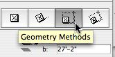
Geometry Methods are the ways of making a shape with a tool. The 'GMs' are only available in the info box, not in the settings. You can switch geometry methods in any tool by typing G.
The first button is one click placement. The object will be created with the default X, Y, and rotation. Example: A recessed light fixture, since it's not stretchy and it doesn't matter how it's rotated.
Second is rotated placement. Two clicks. First is anchor point, second is angle. X & Y will be the defaults. Examples: Anything that you would turn to face a certain direction. A lot of things. Sinks. Light switches. Sconces. Centerline symbols.
Third is rectangle placement. Two clicks. First is anchor point. Second is the diagonally opposite point. The same method is available for polygons (slabs, fills, etc.) Not all objects will be placable this way; only stretchy* ones. By this method you can graphically set X & Y, but you can't give values. Example: Crown Tool in coffer mode.
*Interlude: Stretchiness. Objects are stretchy if they have hotspots in their 2D scripts at the 0, A, & B extents, OR "Hotspots on bounding box" is on in their "Details". Don't worry about this now. An example of a stretchy object is Bed 01 in the Furniture folder. The only way to know if an object is stretchy is to try it, or look in the script. Most rectangular objects should be stretchy.
For "stretchy" placement to work, you have to have a corner set as the insertion node in the settings. If a non-stretchy node (e.g., the center) is the insertion node, you get one-click simple placement. In the plan preview window in the object settings, the insertion node has a box around it. You can choose a different insertion node there by clicking on it.
Tip: When you Option-click (pick up settings) on an object, the node you clicked becomes the insertion node.
The fourth button is rotated rectangle. Three clicks. First is the anchor point. Second is angle AND length of first side (X). Third is length of second side (Y). Example: Crown tool coffer in a rotated space. The same method is available for polygons. If a non-stretchy node (e.g., the center) is the insertion node, you get two-click rotated placement.
The key is not to get hung up on "rotated". I use this method all the time for non-rotated polygons, because you can use R to set the length of both sides on the fly. Example: counter slabs. When placing an object such as a bathtub this way, you need to know which way the object goes; X is first, Y is second. If you do it backwards you get the drain on the long side.
If an object is "linear", only stretchable in one direction, stretchy placement still works. If using rotated placement (4th), the second click only sets the angle, and the third click sets the length. Using the fourth button with a linear object enables you to draw it very much like you would a line. Examples: Lots. Drawing title, crown tool in straight mode, steel and wood beams, cut lines. Sometimes it's hard to predict which side of the "line" an object will be drawn; if it's wrong just mirror it.
Choosing the right geometry method saves a lot of after-rotating and -stretching, and is therefore much faster.
I was going to patch up this post, but I decided to do a new one. The old one is mostly right, I just wanted to add...
• In AC9, there is a menu command for Create Independent Detail. That means you can have a shortcut for it. In our keyboard setup, it's Ctrl+D. (What. Oh. Tools menu. Please don't do it that way. I hate menus.) Also nice, when you create an independent detail, it opens automatically.
• For some reason, most of my projects open new independent details at absurdly zoomed-out views. Like the window is a million feet across. I can't fix this, it's not stored in the prefs. It's always a good idea to work near the origin. You can zoom to the origin quickly by placing an object there and then doing a fit it window.
• Wall sections should be Sections. It's so clear to me now.
• IDs. They still need to be unique, but the ID will now take up to 31 characters, so you can be very non-cryptic. You can have spaces, though I don't use them. I like it to be clear that the first word is the ID. To review, use the ID to say what type of detail is in there, with a number so maintain uniqueness. Use the name for a fuller description. Eave1 Typical, Eave2 Shed, Eave3 Porch.
I have been drawing all the engineering details myself, based on their sketches. I keep these separate by beginning all their IDs with "S_".
• Detail markers: For areas, use Detail Area JAM9. For flags, use Detail Flag JAM81. These markers show the ID in Archicad and the drawing/sheet number in PM layouts. For assemblies, use Assembly Marker JAM81. This marker maintains the ID, which is the same as the (non-autotext) drawing number in each assembly detail. It also gives the sheet number, which is automatic. I have developed the habit of putting my schedules and assemblies on sheet A3-1, so they stay put as sheets are added.
• Remember you can open a detail from any marker, not just the original one.
• The biggest hassle with the detail tool is the fact that you can't put a detail marker in a detail window. Maybe someday. If you need to call out a detail within a detail, use an object. Remember the autotext referencing hack.
Another Hotfix. It's on the Onion, next to the previous one. Here is the list of fixes. I was tragically victimized by the disappearing label thing, so good.
Again, Everyone should run this. Again, You can run it from the Onion, rather than copying it to your machine.
Again, (You can check for updates any time by choosing Check For Updates from the Help menu in Archicad.)
I love the clipboard. I won't paste in my rant about the version numbering, although it still applies. Yup, 9.0.0 v1, now and forever. Watch that build number though.
Take the Archicad competency test. Whee.
I thought it was pretty tough. I managed an 86.
House rules: Since each question is timed (90 sec), I think open book/open Archicad is permitted. If you can open the Attach XREF dialog and figure it out in 90 seconds having never looked at it before, more power to you. The point is to learn anyway.
Unfortunately, they don't tell you which things you got wrong. You'll probably have a feeling though.
I just realized I never mentioned this. I don't use it very often, but that doesn't mean you shouldn't.
In all of the library part settings dialogs, you can search for library parts by keyword.
At the upper left click 'Folder View' and choose 'Find Library Parts'.
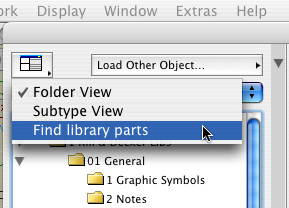
Enter the keyword(s) and click 'Find'. Resist the temptation to strike return; that will close the dialog. You can also refine how the keywords are searched for and limit the search to certain libraries.
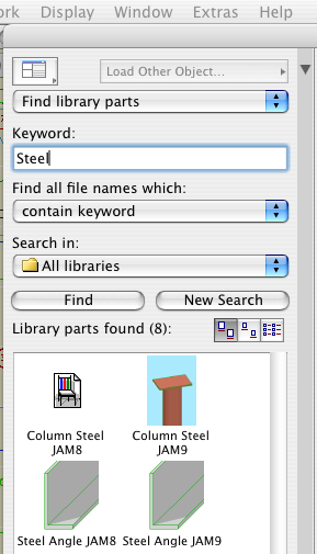
The matching objects are shown. If you highlight an object and then switch back to 'Folder View', you will get the folder of that object.
When selecting objects this way, be careful to use the most current version. The find function will show objects in the 'xOld RND' folder the same as any other. Make sure not to choose them by accident.
Q
When I paste elements, is there a way to select those elements?
A
Complete the paste. Undo (Cmd+Z). Redo (Cmd+Shift+Z).
Q
Working in section, is there a way to reveal selected elements in plan?
A
Yes.
Q
How can I tell what elements were affected by a marquee stretch?
A
Undo, redo. The affected elements are selected. Current story only, natch.
When an editing action is undone, the edited element will typically be selected. Comes in handy.

Elevate, v. syn: lift, hoist, raise, pull up...
It's slow to open the settings dialog when you can use the info box.
It's slow to choose File -> Save rather than typing Cmd+S.
It's slow to choose File -> Merge rather than typing Opt+M.
It's slow to hunt down the close button at the top of a window rather than typing Cmd+W. However: it's slow to bring a window to the foreground so you can close it, if you can click its close button in the background.
It's starfish-slow to choose Edit -> Copy, choose Options -> Stories -> Go Up A Story, choose Edit -> Paste, rather than holding down Cmd and typing C, 6, V.
It's canyon-formation-slow to choose Tools -> Display Order -> Bring Forward, Tools -> Display Order -> Bring Forward, Tools -> Display Order -> Bring Forward, Tools -> Display Order -> Bring Forward, rather than holding down Ctrl and typing 6, 6, 6, 6.
It's slow to right-click and choose Undo, right-click and choose Undo, right-click and choose Undo, right-click and choose Undo, right-click and choose Undo, rather than holding down Cmd and typing Z, Z, Z, Z, Z.
It's slow to drag windows around until you see the one you want rather than use Exposé.
It's slow to go to Display Options when you can use this.
It's slow to go to the Project Map, scroll to the Details part, right-click on it, and choose New Independent Detail, rather than typing Ctrl+D.
It's slow to right-click and choose Open Section/Elevation, or Last Section/Elevation, but unfortunately we don't have a choice.
The fastest way to cancel anything is to type Esc.
The fastest way to deselect is to type Esc.
The fastest way to remove marquee is to type Esc.
The fastest way to switch to the Arrow is to type Esc. The second fastest way is to type Right Arrow, and that's better a lot of the times because it doesn't require that you have no selection and no marquee.
The fastest way to activate the Marquee tool is to type ` (the key above Tab).
The fastest way to activate the Wall tool is to type 1.
The fastest way to activate the Slab tool is to type 2.
The fastest way to activate the Roof tool is to type 3.
The fastest way to activate the Text tool is to type E.
The fastest way to activate the Fill tool is to type F.
The fastest way to activate the Door or Window tool is to type D or W respectively.
The fastest way to change the reference line side of a wall is to type C.
The fastest way to change the geometry method (box, rotated box, polygon, etc) of any tool is to type G. It's also the fastest way to switch the orientation of the dimension tool.
The fastest way to turn on gravity and choose the gravity element type is to type V.
You can do all those things without moving your left arm. You have to move your left arm a little, but it's still fastest to
...activate the arc tool by typing 0 (zero),
...activate the Object tool by typing (letter) O,
...activate the line tool by typing L,
...activate the Dimension tool by typing /.
...toggle the rotated grid by typing K.
There are different ways of doing this, but the first I've been pleased with is the use of Quicksilver.
With Quicksilver running, invoke it (Ctrl+Space, unless you changed it). Type enough of the word "Archicad" to have it pop up on the left. If you have multiple versions, select the proper one from the list below.
Tab. Type "Lau". You should see "Launch Another Copy". Return.
There ya go.
If you don't see the "Launch Another Copy" option, quit Quicksilver, relaunch it, and try again. I have seen this happen after launching another copy, quitting it, and trying to launch again. Seems like a bug.
It isn't needed, but there are times when it's very convenient. You can quickly copy and paste from another project. You can open a placed module without closing the host project. It comes in handy.
Run multiple copies at your own risk. Keep your head on straight. Don't run two all the time. Don't open the same file in two copies at once. Quit the second one when you're done with it. Pay attention to where the second copy is on the dock. All these warnings go double for people who are easily confused, you know who you are.
Another tip: When quitting two ACs, let one quit all the way (the black triangle disappears from the dock) before quitting the other. If you quit them both simultaneously, you're asking for corrupted preferences.
There is a bugfix, they call it a Hotfix, I don't know what that means, update to Archicad. The updater is on the Onion in Archicad Program Files. It's called AC9-1965.
Everyone should run this. You can run it from the Onion, rather than copying it to your machine.
(You can check for updates any time by choosing Check For Updates from the Help menu in Archicad.)
Here is the list of fixes. Most of them don't mean much to me, hopefully some of our (unlisted) issues have been fixed too.
It has been out for several days and no one has complained yet, so it probably does no harm.
Graphisoft's version numbering scheme has become completely ridiculous. Patches like this one should increment the third digit in the version number, making this 9.0.1. But no, they have this quirky "v1, v2" patch numbering deal, but they don't even use that consistently. Sometimes a patch increments the v number, sometimes it adds a "+", and in this case it does nothing, it's still v1. So it's not 9.0.1, it's not 9.0.0 v2, it's not 9.0.0 v1+, it's 9.0.0 v1 Build 1965. You have to know the build number, which should be a really geeky arcane thing, in order to describe the standard current release of the program. Most people outside of software development don't know what a build number is. Ridiculous.
Gravity allows you to "set" elements on top of other elements. Instead of manually setting a Z height, the element will be placed at the top elevation of a slab, roof, or mesh, at the clicked point.
These elements can be placed using gravity: Wall, Column, Beam, Object, Lamp, Level Dimension.
I works in plan and in the 3D window.
You tell Archicad what type of element to set on by using the gravity buttons in the Coordinate Box:
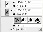
L-R: Off, Slab, Roof, Mesh
You can scroll thru the buttons by typing V.
If more than one of the target element type is present at a given point (e.g., floor, counter, and ceiling slabs), the placed element will be set on top of the topmost element. Elements on stories above will be detected too. In order to get gravity to detect lower elements, you can hide the layers of the elements that are "in the way." (Don't forget the Quick Layers palette.)
Tip: Watch the Z field of the Coordinate Box. It will display the elevation that gravity is using at a given point, so you can see if the element is going to be dropped at the right height.
In practice, I only gravity for a couple of things. It's not convenient to use it to place toilets, for example, since they have to sit on the finish floor, and the toilet usually goes in before the finish floor slab. Since gravity always responds to the topmost target element, it takes some planning and care, and it isn't as natural as it could be.
It's very useful for placing 3D trees on a mesh. No matter where you click, you know the tree is going sit on the mesh, and you don't need to know the height.
It's indispensable for associated Level Dimensions.
Composites allow you to show multiple cut fills in a wall, slab, or roof. I can think of three reasons to use them.
• To display multiple fills. Example: Masonry veneer on a stud wall. This is the most obvious, and probably original, reason to have them. Ironically, such composites don't work at all unless you've made your own windows to handle the masonry openings correctly, which we have.
• To model a wall at one thickness while dimensioning the wall to another. Example: 2x4 with drywall. The wall is 4 1/2" inches thick to match reality, and to properly interact with trim elements. We dimension only the stud portion of the wall. More on the particulars of this below.
• To have elements "break down" nicely when turning a section into a drawing. Example: A joist deck. The deck composite has a skin for sheathing on top of a thick skin of the joist depth. The skins are the same fill, so the slab will appear homogeneous. When the section is unlinked, it's easy to turn the top (sheathing) fill into plywood. Since composites don't have scale-sensitive fills, this is the next best thing.
Composite Setup
• Edit composites at Options -> Attribute Settings -> Composites.
• Composites can 'force' skin attributes onto elements. Instead of setting each wall to have particular pens for background color, skin lines, etc., you can set elements to use the attributes defined in the composite. Generally, I think this is a good idea, on the principle that you should control more stuff with fewer clicks. Further,
• There is a special case where you have to use the settings of the composite: To completely hide a skin separator line. This option isn't available in the element settings. For drywall partitions, you have to treat the interior separator lines in this way.
• The background colors, fill pens, contour pens, and separator pens can be applied from the composite independently. If you want a wall to be blue for some reason, you can change the contour (cut) pen while retaining the background color of the composite.
• You can limit the use of a composite to the wall, slab, and/or roof tools.
• For wall composites, the reference line is at the top.
• As with any attribute, you can use Attribute Manager to pull composites from other projects.
Case Study: Dimensioning Stud Walls
• In the setup of the composite, the checkboxes on the left allow you to designate skins as "Core". You can have multiple core skins, but they must be adjacent. What's core? Well,
• In the dimension tool settings, there is a checkbox, "Dimension Core Only of Composite Walls." So,
• The composite 'Wall 2x4 DW' has only the 3 1/2" center skin set to core. When dimensioning, click on the edge of the wall. (Don't hunt for corners!) This results in two ticks on the core, not the outside, of the wall. The wall is built at 4 1/2", and dimensions 3 1/2". Perfect.
• Summary of why this composite set up the way it is: It's 4 1/2" inches overall, because that's how thick walls are in real life, and it's impossible to pretend otherwise and still get the trim modeled correctly. It's three skins; 3 1/2" in the middle, set to core, so we can dimension to the framing. The three skins are all the same fill, so the walls clean up to the slabs in section. (The slabs are all the same fill too.) The separator lines are hidden in the composite settings, so the walls clean up to each other in plan.
See also: Composite Wall Priorities
Click the flyout on the favorites palette and choose "Load Favorites". Navigate to the favorites file you want. We keep general favorites at 3 Resources : Favorites.
If you already have favorites in the list, you will be asked if you want to Merge or Replace the existing favorites. Unfortunately, "Replace" refers to the list as a whole: All the current favorites will be deleted. To overwrite current favorites with those in the new file, while leaving the others alone, you need to choose "Merge." This has its own quirk: When a matching name is found, you will be offered the options "Skip" (don't overwrite), "Skip All" (which cancels all remaining overwrites), and "Overwrite". There is no "Overwrite All", so in order to accept all the incoming favorites, you have to click "Overwrite" however many times. Another D-minus interface element.
Also, I can't stand the word "favorites". It means I have a great subjective, emotional, aesthetic interest in the item, much greater than in most items. "OMG, I loooooove this 2x4 wall!!!" No. They should be called presets.
You can drag and drop libraries to the Library Manager from the Finder.
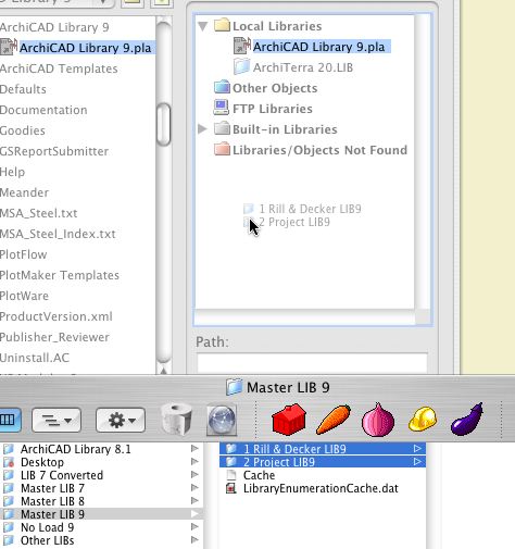
Like this
Since AC8, objects have had the ability to have nodes that edit parameters other than height and width. In GDL jargon, this functionality is called Graphical Editing. These nodes respond to the stretch command as well as the stretch button of the pet palette. Even though they can do things besides stretch.
Since AC8.1, editing nodes have been diamond-shaped instead of round, so you can tell them from the non-editing ones.
In AC9, they decided that wasn't clear enough, and now editing nodes can have a different color. (Options -> Preferences -> Miscellaneous) The default is green, and I haven't been motivated to change it. When you see a green, diamond-shaped node, try it and see what it does.
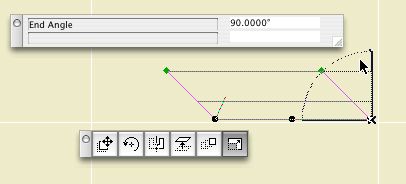
Editing a crown miter
While editing with one of these nodes, a palette pops with the name and value of the parameter(s) being edited. (Some nodes edit two parameters at once.) If you type "N", the value in the palette will highlight and you can enter the value directly, just like typing "R".
In Library Manager, the History tab shows the libraries that have been loaded recently (since the last Clear or Clear All). This list is independent of any particular project.
Typically we use the exact same libraries all the time. But there are exceptions; sometimes you need the version 7 library, for example. If you've loaded that library recently, you can add it from the history tab instead of scrolling through the whole Local/LAN tree.
It's also helpful if you take projects home. When you open a project in a different location, the library manager will come up because the servers aren't there and your local Archicad folder path is different. But the history tab remembers the local instances of the libraries, making it easy to load them quickly.
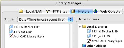
If you load a "wrong" library at some point, you can use the "Clear" button to delete it from the history so you're not tempted by it in the future.
A particularly self-starting member of the Archicad community, Karl Ottenstein, has developed an add-on called QuickDisplay, which allows us to assign keyboard shortcuts to various display options. The commands are toggles, which means you can strike a key turn the Section Depth (e.g.) on, and then strike the same key to turn them off. He has generously allowed this add-on to be used free of charge. Here is the Archicad Talk topic where mad, righteous praise is heaped upon him.
Here is Karl's page with full instructions for the add-on. I will summarize the high points.
Get the file from 3 Resources : Add-Ons. Place it in your local Applications : Graphisoft : Archicad 9 : Add-Ons. Launch or relaunch Archicad.
Your Display menu should now have a QuickDisplay submenu at the end. Here you will see commands for toggling various display options.
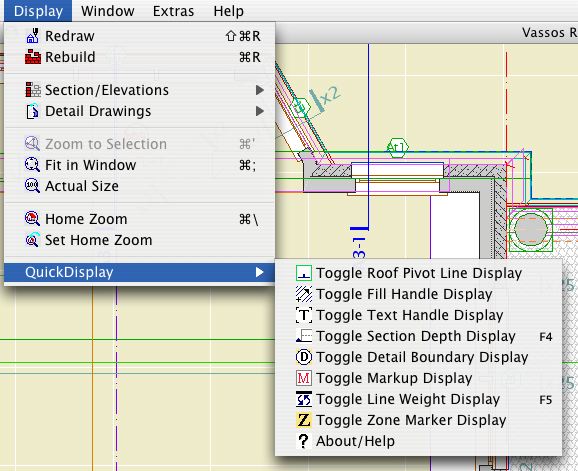
QuickDisplay Submenu
Naturally, and I hope obviously, you don't go to this menu to activate the commands. That wouldn't be much of a shortcut would it. The commands have to be on a menu in order to have shortcuts assigned to them.
As you can see, I only have shortcuts assigned to two of the commands, Section Depth and Line Weights, on F4 and F5 respectively. I toggle the others much less and I don't need a shortcut for them. You can do whatever you want.
I have updated the RND Keyboard scheme with these two shortcuts. You can import the updated scheme at Options -> Work Environment. The scheme is located at 3 Resources : Work Environment : RND Profile : Shortcuts.
For information on assigning shortcuts, see the Archicad Reference Guide, page 153, or ask for help.
Well, there's not much to it. While moving from 7 to 8 was so awkward we had to decide if it was worth it, moving from 8 to 9 is so simple it's hardly worth writing down. The only extra step is to import the Work Environment.
You should be able to simply open your 8.1 project in AC9. You should be able to open your PM 3.1 layout book in PM9. If you don't change the name of the project file, the views should update in PM without fanfare.
That said, I wouldn't make the jump the day before the construction set is due. Use common sense.
Just in case, put a copy of the project in your Old Files folder with a modified name. Don't change the name of the working version of the file. If you do, you'll have to relink in PM.
Libraries: Switch your libraries so the following are loaded:
� From the carrot, within Master Library 9, '1 Rill & Decker LIB9' and '2 Project LIB9'.
� 'Archicad Library 9' from your local Applications : Graphisoft : Archicad 9 : Archicad Library 9. (We load the Archicad Library locally because it's faster and it never changes, so there's so synchronization issue.)
Stop using the Master Library 8 entirely. If you are working with a AC7 project that has been brought forward, continue to use the 7 library as you have been.
On the subject of the cache library, there are intermittent issues with it. If it works for you, use it. If not, don't. If you have weirdly missing parts, this is the first thing to check.
For the new Master Library 9, I copied the whole Master Library 8 to start, and I have been updating and replacing some parts along the way. As version 8 parts get superseded, I move them to the 'xOld Objects' folder. This folder loads, so you can keep using the placed parts indefinitely. For new placements, you should use the newer objects in the normal folders. To remind you, the 'xOld Objects' folder is a jumbled mess, making it very hard to find anything. Don't try.
If you have missing or misbehaving Library Parts, it's probably a change that was made in the 8 library that didn't get copied to the 9 library. You should immediately let me know of any issues so we can dispatch them right away.
This post ties together all the AC9 posts.
Overall AC9 is very much like AC8. Superficially it is almost identical. The changes primarily concern interface and performance.
Performance means it runs faster and better. Interface means:
• Selection is improved. Quick Selection lets you select virtually any element without finding a detectable edge or node. Escape deselects. (Without a deselect function, that QS thing would be a very mixed blessing.) Cmd-Shift restores the old caps lock functionality, letting you 'scroll' through a pile of coincident elements. Objects can have detectable edges. Select with a box under any tool by holding down Shift. To select with a box over a QS-able element, hold down Shift and the spacebar.
• Less switching between tools. The unified pet palettes mean it doesn't matter which tool is active, and the palette commands work better. There are also polyline/polygon editing improvements
• You can switch objects without all the settings reverting to default. There's a search field in the Object (etc.) Settings dialog.
• The Work Environment is much easier to customize, save, distribute, restore. We have toolbars, yay.
Interface changes may seem superficial, but together the whole working experience has been smoothed out and is much more efficient.
There are a few welcome tool improvements. We finally have cover fills on model polygons. The Text tool is utterly transformed. Optional section rebuild is nice, but be careful. Dimension settings is one of those things that's deadly boring until it bites you, so it's good that views now take them into account.
PlotMaker is still PlotMaker, poor thing.
That's all the big stuff. You should peruse the New Features Guide, which is in PDF format on the installation CD, and at 3 Resources : Documentation.
I would have called it 3.2. Others have suggested 3.5. A few very charitable souls say 4.0 would be OK.
9 it's not. To me having the version number the same implies functional parity with Archicad, which makes me laugh, but only to keep from crying.
There are precious few interface improvements. One I do appreciate: In Drawing Usage, drawings on the active layout are shown bold. It also has toolbars, and I use the one with Print and Plot on it so I don't have to keep the various interpretations of Cmd+P straight.
The performance of importing drawings is noticeably better, and that is always welcome.
Other than that, it's still a hillbilly. Dragging a copy is still different, the marquee is still different, no split, no adjust, no Info Box, bla bla !@#$% bla.
So let me be the first to dash your hopes that the '9' signifies anything at all. Sorry.
PS, that hotspot glitch, where the hotspots go dumb after you stretch a frame? Not fixed. You can't believe it either!
The installation process is pretty ordinary. The eye candy is a nice touch. I just want to point a couple things out.
Anywhere in the instructions where it talks about removing the hardware key, ignore it. (Leave the key in.)
It doesn't matter whether you do the key update or the installation first. Obviously 9 won't actually run until you do the update.
You can do 'Typical' installation. The 'Custom' option doesn't allow enough customization anymore, so skip it.
The default install location is now Applications -> Graphisoft, rather than Applications. I'm leaving it there.
I think desktop shortcuts are stupid. If you agree, remember to uncheck the boxes about them at the end of the install. Dock shortcuts are naturally superior.
The documentation PDFs don't install automatically. After the installation finishes, copy the 'Graphisoft Documentation' folder from the CD to the new Archicad 9 folder, within Applications -> Graphisoft. Change the name to simply 'Documentation', or the docs won't show up in the help menu.
The first time you open AC9 it will look weird until you fix your Work Environment.
AC9 gives the option of Windows-style toolbars. I am among the least excited about this feature, since I think mousing around clicking on things is a waste of time when you can use the keyboard, which unfortunately isn't always.
It is my responsibility to point the feature out, and you may do with it what you wish. It is possible to build a toolbar from scratch for just the things you really need, which sounds like good idea, but not good enough to actually do it yet.
I use the Attributes toolbar,

...but only because they broke my keyboard scheme for Attributes.
I also have the Window Switcher in my palette scheme,
... which sort of gives you access to all the windows in the project, except it has crippled detail and section lists, and I haven't really developed the habit of using it.
Toolbars can be turned on and off at Window Menu -> Toolbar Display. You can customize toolbars in the Work Environment. The display and position of toolbars is saved with the Palettes scheme.
Like the new Text tool, the Work Environment is too complex for me to give an exhaustive treatment here. Refer to page 147 of the manual, or page 80 of the New Features Guide, for the full story. Briefly:
All of the user-related options in Archicad and PlotMaker have been gathered together under the Work Environment, accessible on the Options menu. (Shift+Ctrl+~) This includes the keyboard shortcuts, the palette shapes and positions, the toolbox layout, the toolbars, the info box, even the menus themselves.
In addition to having these settings organized, and having more interface elements customizable, all of the environment settings can be saved and imported, making it very easy to set up the environment when a new version comes out, or if you have to delete the preferences.
I have set up a work environment which represents my best efforts at customization through the beta period. You should import this environment when you begin to work in AC9.
(Everything about importing the Work Environment also applies to beginning in PlotMaker.)
To import the environment:
1. Go to Options -> Work Environment. Click 'Import'. Click 'Browse' and navigate to 3 Resources (the Onion) -> Work Environment -> RND Profile.
2. Back in the Import dialog, select the profile and click 'Import'. You should now see 'RND Profile' in the Stored Profiles list.
3. Double-click the 'RND Profile' profile. This applies the schemes of the profile.
4. With the 'RND Profile' profile highlighted, click 'Set as Default'.
You can customize any of the environment components you like. A few thoughts:
� The palette arrangement is for a 23" Cinema Display. It will be a few more days until everybody has one, so some palette experimentation is probably in order. Palette layout is also a very subjective area where reasonable people may disagree. My only tip is that it is better to make an arrangement and stick with it rather than constantly push things around. After you arrange palettes, click the green button on the 2D and 3D windows to get them to conform to the palette positions. Then resize the windows how you like.
� Please refrain from deleting keyboard shortcuts. AC9 has the option of having multiple shortcuts for a single command, so if you want to try something new, just add it rather than replacing.
� More on keyboard shortcuts (Yes, it is one of my favorite topics.): AC9 finally allows the use of the F1-F15 keys on the Mac. We've lived without them for so long that it's hard to know how to react. I have the group switch on F1 and the ghost story display on F2, in addition (see above) to the old Opt+G and Cmd+8. Beyond that I don't know.
� Customizing menus looks like a massive time sink. It does give me another opportunity to say, don't waste your time going to menus, use the keyboard. I have not customized my menus at all, because by and large I don't know or care where on a menu a command is, because I rarely get them that way.
� Don't mess with the Info Box. I have invested a fair amount of time in refining it, and the result is the definitive optimization, probably in the world. Serious! Ask to see the spreadsheet. It is designed to be vertical, one tile wide, long enough to show all the tiles on the most complex tool. (You have to guess.) If/when pushing palettes around, keep the Info Box in this shape.
If you make changes in a scheme: In order to get the changes to stick you have to highlight the top level of that scheme, then highlight your scheme name on the right and click 'Redefine'. Example: You modify shortcuts under 'Keyboard Shortcuts', but to save the changes you have to highlight 'Shortcut Schemes'.
Cover fills are the long, long, long-awaited ability of model polygons (slabs, roofs, meshes, zones) to display fills in plan.
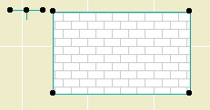
A roof and nothing but a roof.
This going to mean a lot less drawing over things to show fills and to get elements to hide one another.
Cover fills have all of the features of regular fills, including background pen, local origin, and rotation. Roofs can automatically rotate the fill pattern to align with the roof slope. You can set the cover fill to be the same as the vectorial hatching on the 3D material.
Display of cover fills is controlled by a new display option.
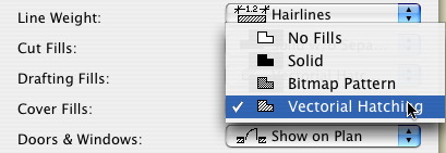
Selecting 'No Fills' puts the model polygons the way they were in AC8.1.
Notice that there are now a total of three fill display options. Further, 'Polygon Fills' has become 'Drafting Fills' and 'Construction Fills' has become 'Cut Fills'.
The distinction between Cover, Cut, and Drafting fills is called the Fill Category. You need to be aware of this because you can actually draft a cut or cover fill, which will display according to the relevant display option.
In Options -> Fill Types, you can limit the categories a fill can be used for. For example, shingles can't be used for cut fills.
Since you can set the category in the fill settings, and not all fills can be used for every category, you may find in a certain case that some fills are "missing". If so, check that the fill category in the settings is "drafting".
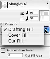
Fill Category in Info Box
AC9 brings the ability to save views with different dimension settings. The most prominent example would be the desire to dimension plans with feet & fractional inches, and site plans with decimal feet. Now you don't have to switch dimension settings back and forth, or explode dimensions, or other such tedium.
To make it easier to maintain the dimension settings, we use the long-standing, little-noticed Dimension Standards.
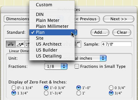
"Standards" in Dimension Preferences
There are two standards which we use in our views. "Site" is used for site plans. "Plan" is used for everything else. You could also set a standard for details if you wanted to display smaller fractions.
The view sets in the templates are configured to use the appropriate standard. For running projects, you will have to redefine your site plan views. Set the "Site" standard in the dimension settings, then redefine the view. (It's just like changing the scale or the layers.) Your plans should be OK, but it never hurts to check.
So now, views save scale, layers, display options, zoom, and dimension standard.
The GDL implementation in AC9 adds the option for the object designer to make edges detectable in plan for the purpose of selection.
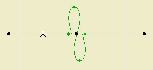
Detecting Cutline JAM9
This ability can be added to any line or arc. I'm working it into the libraries gradually, going for maximum convenience and minimum nuisance. In addition the cutline above, all the JAM9 trim tools are detectable by the front edge. This should make easier to select trims, which tend to coincide a lot. I am listening for suggestions.
Look closely at the image above and you will see that the special snap points (midpoint, etc.) show up on these edges.
Remember that this is only for detection. There's no polyline editing ability. You can use such edges for splitting and adjusting, but not Cmd+clicking. (Yes, I reported that.)
Text editing in AC9 is completely overhauled, one of the few features that is.
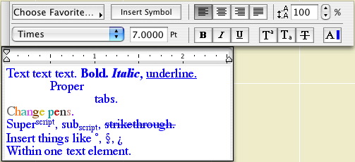
Different.
The changes to the text tool are too great for me to cover here. Generally, it is more like editing in Word. All of the typical variations in text are available, and the shortcuts for bold (Cmd+B), etc., work as they should. You can mix any text effects within a single text element. Cmd+A works to select all the text when editing a block. Text can be stretched and expanded. Text can be copied and pasted from Word, with complex formatting preserved.
Text blocks can also have an outline box, and a background color, and you can control the offset of the text to the block edge.
It's a lot of stuff. If they had styles they would be done.
You should look over the section in the manual about the new Text, which starts on page 306, and/or the section in the New Features Guide, page 74.
Here's a couple of minor improvements to the polygon and polyline editing palettes.
At a polygon edge, there is one new button that always appears, and another that appears in a particular situation.
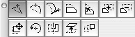
Polygon Edge Palette
The third button turns an edge into a curve, using a tangent instead a point on the curve.
The fifth button turns a chamfered corner into a pointed corner. It will only appear when you click on an edge between two other edges that would converge at a point outside the polygon. Example: turning an octagon into a square.
If you select a polyline and click on the end node, you get a palette with the third button shown here.
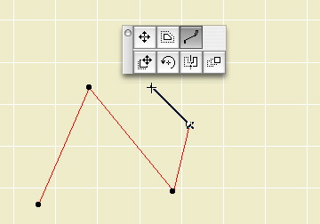
Add to polyline
If you click on this button, you can add nodes to the polyline. Good feature, half-implemented: You can only add straight segments. Sigh.
In AC9, the pet palettes for the arrow tool transformation functions and the element-specific editing functions have been combined. This is awesome.
Here's the Mesh palette:
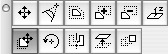
In past versions, there was one palette which came up under the arrow tool, which had the dragging, mirroring, etc. buttons. Then for each tool there was a different palette which had the buttons for moving a node, curving an edge, filleting, etc. Now, regardless of whether you have the the arrow tool on, an expanded palette appears which has all the buttons of both groups.
This smoothes out the whole editing process because there's a lot less switching to the arrow tool and back.
They also improved the transformation (rotate, etc.) functions of the palette. Now you might actually use them. If you select rotate or mirror, you can select the base point for the transformation, like with the regular command. In 8.1, these palette functions would take as the base point the point where the palette came up, making them IMHO useless.
Shift-click accumulates selection. (I know shift-click accumulates selection! I know that!)
Prior to Archicad 8.0, the shift-click functionality could be modified by activating Caps Lock. With Caps Lock active, shift-clicking on unselected elements would select the clicked-on element and deselect all others. This was invaluable in getting a particular element out of a pile. But it made newbies cry so they got rid of it. (I was typing, notes, with all caps, an-and, then I went to uh, uh, uh, select, something, an-and, caps lock was still on, an-and, uh, uh, uh, the selection didn't accumulate, an-and, I had to move my left hand a quarter inch, to, to, to, turn caps lock off!!! MMMWAAAAAHHHHH!!!!)
In AC9, they have restored the functionality, while throwing the newbies a bone by not using the caps lock key to do it.
If you hold down Command along with shift, the selection will rotate through the elements at that point. With a particular tool active, it will rotate through the elements of that type. Don't forget Quick Select!
AC9 grants one of my longest-standing wishes: You can set section windows to rebuild only when you say so. Unfortunately, the implementation of the feature isn't perfect. Fortunately, the performance improvements of AC9 make the feature less critical than it was. Now that we have it, we can live without it, and the workflow issues mean we probably should.
In AC8.1 and earlier, the sections would rebuild if there was any change in the model, even if the change didn't effect the section in question.
They also rolled the drawing (unlinked) section functionality in with the other rebuilding options, so that process is slightly different.
The rebuilding options are contained in the settings of each section independently. In the section settings you see this:
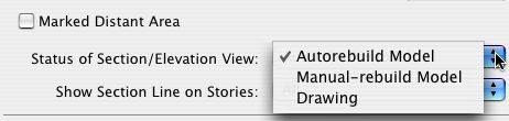
Autorebuild Model is the old way, and the default. You open the window, it rebuilds.
Manual-rebuild Model means the window won't rebuild until you say so. Note: The command to rebuild a manual-rebuild section is different from an ordinary 'Rebuild'. The command is Display -> Section/Elevations -> Rebuild from Model. It has a different shortcut, Cmd+Opt+R. Even more confusing, for an autorebuild section, the standard rebuild works as always.
Drawing is the same as the old 'unlink'. To turn a section into a drawing, select this option. The Unlink command is gone. The advice about dragging a copy in a section drawing window still applies. You can turn a drawing section back into a model, but Archicad will delete all the 2D elements that it initially drew. You can update the drawing, keeping it a drawing, with the Rebuild from Model command, Cmd+Opt+R, as with the manual-rebuild model.
So the manual-rebuild model should save a lot of time, let's do it. Not so fast. We hit the wall when we go to PlotMaker. As of now there is no facility to tell PM to update a manual-rebuild section window. That means you have to, well, manually rebuild the section before updating the view in PM. That means you have to remember. That means sometimes you'll forget. That means you'll have drawings you think are updated but aren't. The word for this is 'bad'.
Another option is to turn the section back into autorebuild before going to PM, but you'd have to remember that too.
As it stands, manual-rebuilding will save you time in Archicad at the risk of de-automating part of the layout book. As such, I can't recommend the manual-rebuild section functionality until the PM problem is solved.
Quick Selection is the ability to select elements in the plan and the 3D window without finding a detectable edge or node. (The 3D window has had this feature for while, it just didn't have a name.)
With Quick Selection active (it is technically optional), you can click anywhere on on element to select it, either with the arrow tool or by holding down shift. It works for all elements, including objects. (Assuming the object contains polygons.) Example: Rather than finding the corner of the bathtub and then scrolling the pile of elements occupying the corner, just click in the middle of the tub.
Successive clicks will scroll through the elements in a given area. Successive shift-clicks will accumulate the selection.
The QS status is shown by the button at the top of the info box:
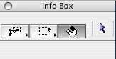
The Quick Select button. The magnet thing.
While QS is active, if the cursor is over a selectable element, the pointer will have a magnet attached to it, like the magnet on the status button.
You can temporarily suspend QS by holding down the spacebar. You'll need to do this to select with a box where the cursor is a magnet.
I have never deactivated QS, and I don't recommend doing so. Following this advice means some habit-changing.
In practice, especially in section or model layer combinations, the magnet cursor will almost always be on, because you will almost always be over something selectable. If not a fill, a slab, if not a slab, then the site mesh. This means: You will find it nearly impossible to deselect by clicking in "empty space", because there isn't any. In fact, it's worse than that. As you casually click on you floor slab, not realizing it, you also begin to drag it. Eek.
Quickly develop the habit of using esc to deselect. As you develop the habit, pay attention and watch for unintended drags. Don't give up! QS saves lots of aggravation once you get the hang of it. Resist the evil voice in your head telling you to turn QS off and go back to the old way. If I was training a new user today, I wouldn't even tell them about deselecting by clicking nowhere.
AC8 brought esc-to-cancel, a standard functionality in most software. In AC9, esc is way more useful.
Esc will activate the arrow tool. Unless...
There's a marquee present. If so, esc removes the marquee. Unless...
Elements are selected. If so, esc deselects. Unless...
There's a command in process. If so, the command is canceled.
In other words, with a command in process, a marquee present, and a non-arrow tool active:
The first escape cancels the command. The second deselects. The third removes the marquee. The fourth activates the arrow tool.
Former autocad users will want to redevelop their "esc-esc to cancel-deselect" habit.
Further strikings of esc in future releases of Archicad will close the project, quit Archicad, shut down the machine, and drive you home. Maybe.
You wish you could turn (e.g.) a solid door into a french door while maintaining the other settings (trim etc.). Well wish for something else!
Select an object and open the settings. Navigate to the object you want. Hold down Command and Option and click on the new object. Any parameters the two objects have in common will hold their values. Parameters in the new object that aren't in the old one will keep their default values.
In our door example, all of the settings related to trim, materials, open angles, etc. will be saved. The divisions of the french door will be the default divisions.
Very exciting.
Archicad 9 was officially announced at ACUE in Nottingham last week. It is expected to ship around September 27. We will be deploying the upgrade soon, but not immediately. More on this later.
As you may know, I had the privilege of participating in the beta test program for the new release. Graphisoft also had the privilege of having me participate. ;-) This is good for us since I have had a long head start in preparing for the update, so we will be able to hit the ground running.
We all remember, try as we might to forget, the transition to AC8. It was extremely difficult on a number of levels, and honestly you don't know the half of it. The difficulties had two main causes. First, the program had been radically redesigned and rewritten under the hood. Second, it sucked. The latter in particular was a big problem.
I can tell you with complete honesty that AC9 doesn't have either of these problems. There are no radical changes to the program, though there are several valuable new features. (Many argue, and I might be one of them, that the version should be called 8.5. Whatever.) More important, the quality, speed, and stability (non-crashing) of this release are far greater than the early releases of AC8. In Nottingham, Graphisoft showed us benchmarks which indicate that AC9 is the first version since AC7 to be faster overall than AC7. The performance improvement is noticeable.
Further, while this may not interest you, it certainly affects you, Graphisoft's internal procedures have made a 180 degree turn for the better, making another AC8 disaster very unlikely. Mainly because everyone involved with AC8 has been fired. Really. In the beta testing I observed first-hand a much improved quality-control policy, and a real interest in hearing from users and addressing their concerns.
Since AC9 isn't much different in the nuts and bolts, we will be able to transition quickly without undue disruption to workflow. Unlike with the AC8 transition, we will not meditate on whether to move a project over. It will be moved over. Assuming Salamander Farm goes the way of all flesh, we will soon be running only one version of Archicad.
I am working on polishing the new templates, library parts, and the upgrade procedure itself. Once this stuff is to-a-point, we will set a date to do the move. I will be posting here on some of the new features for reference, and I envision about two tech meetings on the essentials. Graphisoft has done well in releasing an easily-deployable update, and I don't want to be the one to mess it up!
Attribute Manager is a utility for managing (creating, deleting, getting from somewhere) attributes (pens, layers, layer combinations, materials, linetypes, fills, composites, locations, zone categories). Its functions overlap with the individual attributes dialogs accessed from the Options menu. But it does at least two unique and indispensable things:
• Tells you if an attribute is in use before you delete it.
• Enables you to quickly, directly get attributes from other projects.
We will look at how to get a composite from another project into your own.
v2 is here. It seems to work.
Two gotchas so far (maybe you'll be lucky): 1) In PM, after stretching a frame with the arrow tool, frame nodes will not be detectable until you rebuild. Scroll-zooming forces a rebuild so that takes care of it. 2) After rebuilding drawings via drawing usage, the layout window becomes unresponsive. Minimize the window to the dock using the yellow title bar button. Bring it back, and it's OK. I think GS's beta testing consists entirely of demonstrating the software to their dogs. I digress.
The howto follows.
The project templates' plan window now has a drawing area object and corner alignment hotspots for each sheet size. Delete the ones you don't need. Move the object around to center the plan, then move the hotspots to the corners on each story.
But you don't use the drawing area and the hotspots to align the plans in PM so the plans stack in a professional and aesthetically pleasing manner? Well you better start.
Intersection group number is an AC8 feature that controls which layers clean up to each other. If the numbers match, they do, if not, they don't.
Which you need to do from time to time, for several purposes.
Don't.
Remember our layer system is the result of lots of work on lots of simultaneous problems. As such, it is hard to improve but easy to break. Trust me. Further, layer management is far and away the most unpleasant standards task in the whole operation. You don't want to get involved.
OK, sometimes you have to. Maybe you really need a new layer. Maybe I told you you need one. If you're going to do it, you'd better do it right.
Select an existing LC that is similar to the one you need to make. Click 'New'. (The other one. Lower left.) Put in the new name. Make changes to the showing and hiding of layers on the right. Click 'Update' at the bottom. OK and save.
You will probably need to create views for the new LC.
See also:
Creating Layers
On the Archicad Help Menu, beneath the first two items, you will find two lists of items.
The first list consists of links to PDFs, including the Archicad manuals. The PDFs reside in the Documentation folder within the Archicad folder. Any PDF placed in this folder will appear in the menu.
The second consists of links to web sites. The links reside in the WWWLinks folder within the Archicad folder. Any link placed in this folder will appear in the menu.
Update: I have expanded on this topic here". I have strikethrough'd the really wrong bits here.
(I am planning a tech meeting for this topic the week of the fifth.)
Q What is a detail window.
A new kind of window in AC8. A hybrid of a section window and a patch.
Like a patch, they can be generated from existing geometry. Like a section, they can be renewed. Unlike a section, they cannot be model views, only drawings.
Q What are they for.
At 3 Resources/AC Program Files you will find AC8.1 v1 1410 USA Updater, an update patch for 8.1. Go ahead and run it. It requires a restart. I have no idea why.
Forgot something else...
In 8.1, we have the option of placing a marquee to limit the print area, instead of fiddling with the window itself.
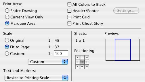
Print Marquee Area, among other things.
Click 'Copies and Pages' and select 'Archicad' to view these options.
As far as I know, this option has always existed, but I've only fully internalized it recently.
Try this display option in your working plans and sections views:
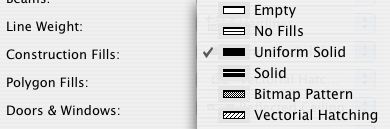
Uniform Solid and friends
It causes walls in plan, and all elements in section, to display as solid fill of the pen of the fill pattern. In plan, this means that only the corner of the wall itself can be detected, not the inside drywall corner. This eliminates the problem of accidentally aligning counters, floor fills, and such to the core of a stud wall.
I have taken the liberty of changing the working views in the templates to employ this option.
This is about four years old but I wanted to explicitly point it out...
All the attribute-related options on the Options menu (Pens and Colors, Line Types, etc.) use the Ctrl+Opt+Cmd modifier combination with the initial letter of the attribute.
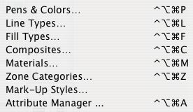
I'm sensing a pattern.
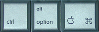
Oh, those three.
Update: A couple of these (notably materials and composites) broke in AC9 due to conflicts with default shortcuts in OS X. Pens and fills still work. Keep the Attributes toolbar on.
Obsolete. We're not using cach libraries at this time.
It's good to have the libraries on the server so we are all up to date all the time. But loading libraries from the network is slow. This is a big problem when updating views in PlotMaker. The satellite library is an attempt to have it both ways. It has been bumpy in the past, but I've tried it again and can cautiously recommend it.
Forgot something...
The copy transformation modifier key is now Option instead of Command. Instead of drag a copy being Cmd+D+Cmd, it's Cmd+D+Opt. Same for mirror and rotate.
Update: For AC10 I put the quick layers commands in the main toolbar, so you don't need the palette.
Window | Floating Palettes | Show Quick Layers (Ctrl+L).
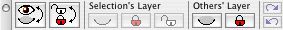
Quick Layers Palette
The Quick Layers palette enables you to:
Unhelpfully:
• Toggle the display of all the layers. All the showing layers become hidden, all the hidden layers show. Shrug.
• Ditto for lock/unlock. Shrug.
Very helpfully, under 'Selection's Layer':
• Hide, lock, or unlock the layer of selected elements, even for multiple layers at a time. Similar to the 'Layer' sub-context menu.
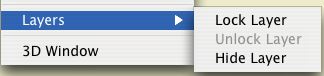
Remember?
Unhelpfully again:
� Hide or lock all layers. Big shrug.
The palette will close when you quit Archicad, unlike the standard palettes. Just reactivate it when you start with Ctrl+L.
AC8.1 improves Composites substantially. A summary.
Starting Monday, Dec. 8, we will be moving to Archicad 8.1 and PlotMaker 3.1. This is a relatively minor feature update, with noticeable performance and interface improvements. No, it's not perfect, but it is better. Unlike the 7 to 8 update, we will move current projects over.
Don't forget: In AC8, the escape key now performs the cancel function. This makes it consistent with all other software in the solar system. 99% of the time, hitting ESC will be faster than mousing over to the Cancel button, or right-click-canceling.
It's also another beautiful, inspiring, timeless, indestructible tower on the magisterial edifice that is The Keyboard, as compared to the moldy-straw-1st-little-pig-shack of Mousing Around Clicking Buttons, Menus, Sub-menus, and Sub-sub-menus.
In other words, learn the shortcuts, and use them. And we'll plan our escape.
Tech Meeting Notes, Archicad 8 Navigator, July 29, 2003.
Here's a summary of the single key commands in Archicad. I didn't know some of them either. G & C will save you a lot of mouse milage.
- A - Activates the Angle Coordintate
- B - Activates the Base Value (in the Info Box)
- C - Cycles through the Construction Methods
- D - Activates the Divisions Snap Option**
- G - Cycles through the Geometry Methods
- H - Activates the Angle Bisector Modifiers**
- O - Activates and switches between Offset and Multiple Offset**
- P - Activates and switches between Parallel and Perpendicular Modifiers**
- Q - Cycles through the Quick Alignment Methods (when Shift-constraining)
- R - Activates the Radial Coordinate
- S - Cycles through the Grid Snap Options (former esc function)
- T - Activates the Top Value (in the Info Box)
- X - Activates the X Coordinate
- Y - Activates the Y Coordinate
- Z - Activates the Z Coordinate
- 2 - Pans Left
- 4 - Pans Down
- 6 - Pans Right
- 8 - Pans Up
** Broken in OS X. Too bad, epecially P.
Purpose and locations of the Archicad and PlotMaker preferences, and why you care.
There is an issue in AC8 v3 where certain details can not be deleted or renamed. Graphisoft Tech Support has provided a solution.
I have fixed the templates, so this shouldn't be a problem for new projects, but I'm sure there are some running projects that need to be fixed.
When installing Archicad, don't do the Easy install. Custom install is faster and saves space.
This is a reprint of the notes for the Libraries & Objects tech meeting a while back.
I have announced this before, but just to reiterate, emphasize, clarify...
New projects should be begun in Archicad 8.