Smarter cleanup please.

Smarter cleanup please.
Archicad 10 offers the ability to place a live drawing list, which will automatically list the sheets in the set. It works, for the most part, with a little tweaking.
Background: Navigator Theory
Issue: You need plumbing (or mechanical, etc) plans, which aren't set up in the templates.
This is a piece of cake.
Archicad 10 finally gives us the ability to place PDF files in layouts, as well as other project windows.
PDF-in-layout will become the standard method of placing non-Archicad info in drawing sets. Any file (Word doc, spreadsheet, etc.) can be saved as a PDF via OS X's Print PDF facility. In the current templates, the abbreviations and general notes are PDFs. It's the new stickyback.
Since you can place PDFs as model windows too, you may find it more convenient to use PDFs for topo surveys, plats, and the like.
PDFs become drawing elements. Since drawings are polygons, you can crop the PDF however you like with the pet palette.
There are several methods for placing PDFs, in rough order of convenience:
• Drag the PDF file from the Finder into the Archicad window.
• Use the Drawing tool. Click where you want the file to land.
In a layout window, you get the 'Place Drawing' dialog. Choose 'External Source' and then 'Browse'. Navigate to the file you want.
In a model window, you can only place an external drawing, so you immediately get the Open dialog, where you can choose the file.
• File -> External Content -> Place External Drawing. Select the drawing in the dialog box. (Least convenient method IMO.)
Whatever method you use, you can only place one page of a PDF at a time. If the PDF has multiple pages, you will get a dialog box where you can choose the correct page. To place multiple pages requires multiple drawing elements.
Since they're drawings, they can have titles, but they usually shouldn't, right? Make sure the title is set to 'None'.
Like all external drawings, PDFs will be Manual Update by default. If you modify or re-save the PDF, remember to update the drawing. I don't recommend setting external drawings to Auto Update.
If you take the project file off the network (home, e.g.), you will get a warning that the source file for the PDF can't be found. This is usually not a problem. The drawing will still appear, you just can't update it. When the project is reunited with the network, the warning will go away, and you can update the drawing as needed. (Note the similarity to Hotlinked Module behavior.)
Location: 01 General / 1 Graphic Symbols
A custom drawing title object for plans only. It's very similar to the old Drawing Title RND 9a.
As you know, in AC10 we use the new automatic drawing title marker objects. All drawings except full size plans should use the automatic titles.
Why do plans still use an object? Because we want the titles to stack through the sheets, and the best way is the multi-story feature of conventional objects. There's no easy way to align elements across layouts.
Since we're sticking with the object for plans, and not using the object for anything else, I decided to optimize the object for plans, so here we are.
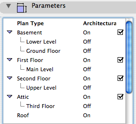
In the templates, there is one of these guys for each plan. In setting up the project, you need to set up the plan titles. For example, turn the attic off if there's no attic. The best way to do this is all at once: Turn all the note layers on, select all the title objects, and change their story setup.
The different names for a given story are all hooked together, so if you turn 'Main Level' on, 'First Floor' will switch off.
Place the object on the lowest story that is in use. If that's the basement, turn 'Basement' on. If not, turn it off and 'First Floor' will take its place. Etc.
After some experimentation, this is the best method I can find for using external, standard details. It definitely has room for improvement. The biggest improvement would be for AC to allow detail markers to reference external drawings. It's a huge hole in the program that has to be fixed. In the meantime this isn't too bad.
The executive summary: Copy details from projects and clean up their layers and other attributes. Place the details in a central PLN file, one per story. Or, draw them from scratch in the central PLN. Publish modules of the details. Hotlink or merge the modules into detail windows of running projects, and use detail markers to refer to them normally.
In this example I'm talking about the wall and other assembly types. It could used for any standard details you would like to share. Also, we will use this as a standard method beginning with AC10. In the meantime, everything here which concerns placing detail modules can be applied to current assembly modules at 3 Resources / Modules / Assembly Types.
It would nice to have standard details in one place, where any project could use them with no need to redraw anything. These would be standard assembly types, foundations, flashing, etc.
You can place views from any number of external project in a layout book in 9 or 10. The trouble comes in when you want to refer to the external drawing with a detail marker. Even in 10, this is still not possible.
So we have to consider a couple imperfect alternatives.
• Maintain modules, one for each detail. Merge or hotlink the modules into detail windows within the project. Refer to the internal detail drawings normally.
If you hotlink the modules, they can be truly standardized, with any changes distributed to all projects by updating hotlinks. The drawback is the module reference warning if you take the project off network. No harm, just hassle. (You could choose to break the hotlink, which would leave the detail intact, but it wouldn't be connected to the original.)
As an alternate to separate modules, you could place all the details in one project file, with one detail on each story. In this case, merging is not an option. You would hotlink the stories and optionally break the hotlinks.
Then you could use Publisher to create modules if you wanted them.
The one-project method also makes attribute management easier. It's important to rigorously control attributes so you don't 'contaminate' the current project.
Using hotlinks to the detail project stories presents a problem: You can't insert a story without breaking the links in projects. Ouch.
• Use external views directly, even though the referencing doesn't work. You would need a fixed ID, specific to the detail, which would appear in a drawing title object in the detail, and in the detail ID in the project. These IDs would bear no relationship to the sheet. Weird.
Conclusion:
• Create the details in a project file, one on each story. This is simpler generally and helps with the attributes.
• From this project, publish modules of the details. Then the modules themselves are hotlinked or merged. The detail project becomes an administrative resource; users don't interact with it directly. The stories can be managed for the convenience of the 'detail administrator'. Whenever a detail is added or changed, republish the modules.
• Hotlink or merge the modules into project detail windows and reference them normally.
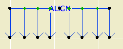
The alignment symbol. Slightly improved from the JAM8 version: You can have more than two arrows, up to a total of eight. That should be enough. For the extras, you can turn on Equal Spacing, or locate each one individually.
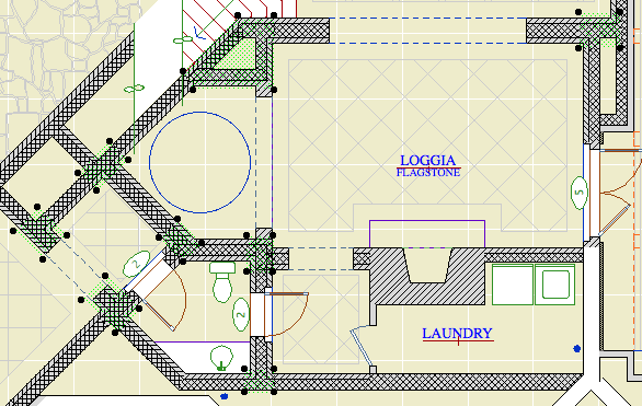
In framing plans, it's often helpful to show the walls on stories below with dashed lines. Especially roof framing. Well how do you do that.
I'm still not totally comfortable with the SK routine. For example, if you place the SK title block in the plan, you run into trouble when the SKs overlap. And it's a pain to set the scale when using the title block within PM.
Here's what I'm doing as of now. It probably still can be improved, and as Vassos starts needing revisions I'll probably make further progress. This shouldn't be interpreted as standard right now.
Create a new layout in the SK folder. Use the SK Master, the one without the title block. Name the layout what you what to print on the SK. The autotext in the title block object will render the layout name.
Set up the title block in the AC detail window with the date, sheet ref and scale. Import the 'xSK Title' view into the layout. (Not the Master Layout.) Tip: In the Navigator, copy the title block drawing from the 'SK Blank + Title' Master. (Drag while holding Option.) Make sure you update it.
Select the title block drawing and explode it. That turns it into 2D elements. When you change the title block in AC later, this layout won't care.
Import the relevant view(s) to the SK layout. Tip: Copy the views from wherever in the set they live, and update.
Interlude: Drag-copying in the Navigator. You can easily move drawings between layouts by dragging them in the Navigator. If you hold down Option while doing so, you will make a copy. You can be sure you are copying rather than moving when you see the green plus-sign circle.
Once the drawings are in place, go to drawing usage, select them, and click 'Break Link'. This basically turns them into PMKs that are embedded in the layout book. In drawing usage their status will read 'Embedded'. When the views from which the drawings came are updated, these PMKs will be untouched.
The combination of exploding the title block and breaking the views' links means that the SK layout will stay as it is, whatever else changes in the project and layout book.
The SK thing is a tricky area, since AC and PM are not naturally inclined towards revision control in their current state.
With the detail tool and a well-developed model, trim details can be developed pretty quickly. The oddball is rakes, since there's no way to cut a non-plumb section. You need to take extra steps to correct the distortion arising from cutting through sloped elements. A conventional resize won't work, because you can't restrict it to one axis.
The trick is to create a patch and then adjust its vertical dimension.

1. Marquee the area you want in the detail and create a patch.
2. Figure out the conversion factor. There's at least two ways to do this, I like the first one.
a. SIN(90-RoofSlope). Example: 10/12 pitch is 39.8056º. SIN(50.194)=0.7683.
b. (True thickness of roof) divided by (plumb cut height of roof). These values are readily available in the info box. Example: A 10" roof at 10/12 pitch has a plumb height of 13.017". 10.0/13.017=0.7683. Tip: Much easier if your working units are decimal.
Four decimal places is fine. If the factor is greater than one you've made a mistake.
3. Now you can either a) drop one line into the patch's 2D script, or b) calculate the adjusted height of the patch and change it in the settings.
3a. Open the patch object. At the top of the 2D Script type:
MUL2 1, [ConversionFactorFromAbove]
For the 10/12 pitch, that's:
MUL2 1, 0.7683
Save the object.
3b. Multiply the 'natural' height of the patch by the conversion factor. Select the patch, and put the converted height in the Y field.
Either way, you're squeezing the patch so the vertical dimensions of the elements are right again. Horizontal is unchanged.
4. Create a detail. I recommend an independent detail, since the source view data for a detail generated from the window will never be right; it will be pre-patch distorted, and you'll have to delete all of it.
5. Place the patch object in the detail window. Tip: Cut and paste it from the section window. You don't want it hanging around the section anyway.
6. Select the patch and explode it (Cmd+=). Now you have 2D lines and fills as if you had generated the detail directly. Except: All the elements are of one big group. Also, there's an 'Air Space' fill element in the shape of the patch, which you don't need.
You can trash the patch from the library if you wish. It is no longer needed. On the other hand, it doesn't take up much space. Whichever.
Obsolete. Referencing in AC10 and later doesn't work this way.
It sure is nice the way detail markers know where their drawings are placed. It sure would be nicer if we could as easily refer to any placed drawing. If you could place dynamic drawing and sheet references in section marker objects, and call out enlarged plans, and write notes of the form, "Do this like this, see detail A3-5/12." And since you can't place details in detail windows, use an object detail marker there.
Well, you can refer to any placed drawing. But I wouldn't call it easy. In fact, I think this is the most annoying worthwhile thing in all of ArchICAD.
Here's how. We'll do the drawing number first.
Import the drawing to a layout.
Right click on the drawing (in the layout or in the tree) and choose "Set as Autotext Reference".
Activate the text tool. Start a text block by double-clicking. In the text editing area (at the cursor), right-click and choose "Insert Autotext for [DrawingName]" -> Drawing Number. This results in a blob of gibberish like "< DRAWINGNUMBER_R ><9BEA5D4E-8700-11D8-8AA9-000A95A7B33A>". Copy this. Tip: Cmd+A works to select all while editing text. So, Cmd+A, Cmd+C.
Return to Archicad. Open whatever it is that needs the reference, e.g., a detail marker object or a text block. Paste into the appropriate field or location.
Of course, you usually need the layout number too. Return to PlotMaker. You should see the open text block as you left it. Delete the DRAWINGNUMBER stuff. Repeat the process, this time choosing "Layout Number". Cmd+A, Cmd+C, Back to Archicad, Paste.
A detail marker will look like this in Archicad:
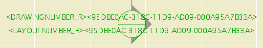
The gibberish bits resolve themselves in PlotMaker, giving the location of the drawing you set as autotext reference in the beginning.