On Land

Environment Information
At Rill Architects we run ArchiCAD on macOS. If you work at Rill, this is your stuff. If you don't, but you work in ArchiCAD, you may find something interesting. Anybody else, I don't know.
RSS
Documentation Archive

All Entries | 1 | 2 | 3 | 4

Here is a method for keynotes in vanilla Archicad, except it doesn't work. It takes a classification, three properties, an object, and a schedule:

A classification called Keynote.

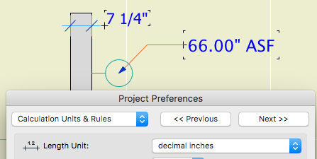
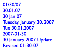
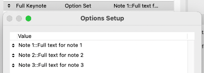
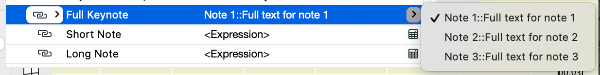
A property called Full Keynote, string type option set. Each option consists of the short note, a separator, and the long note. The separator can be anything that doesn't occur in content, such as "::". The short note is displayed in the view, as an object. The long note is shown alongside the short note in a schedule.

A property called Short Note, string type, using the expression SPLIT (Full Keynote, "::", 1). This property will output the short note part of the Full Keynote property.

A property called Long Note, string type, using the expression SPLIT (Full Keynote, "::", 2). This property will output the long note part of the Full Keynote property.

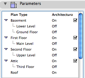
All three properties are available to the Keynote classification.

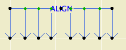
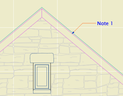
An object, maybe called Keynote Object, which acts like a label, with text and a leader. The text is the Short Note property. The objects are classified as Keynote.

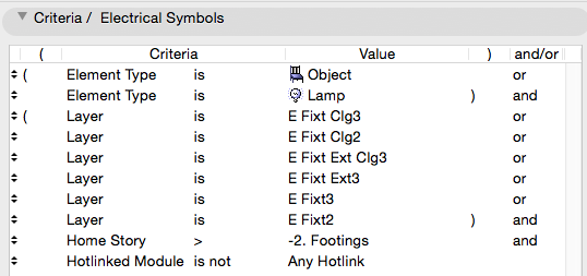
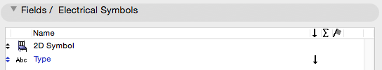
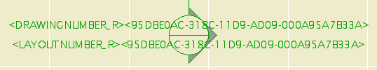
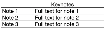
A schedule of the Keynote Objects, which shows columns for the Short Note and Long Note properties.

The format of the Full Keynote options is:
Note 1::Full text for note 1
Note 2::Full text for note 2
Note 3::Full text for note 3
etc.

Keynote Options

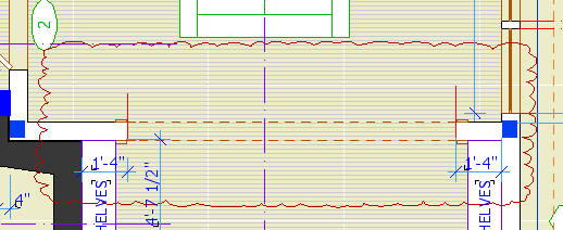
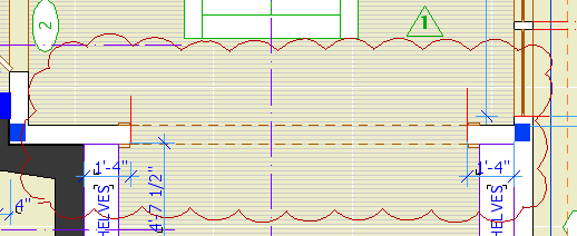
Options are created as needed in the Property Manager. The user places Keynote Objects and selects the desired Full Keynote property option.

Keynote Options

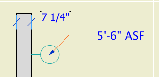
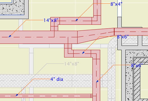
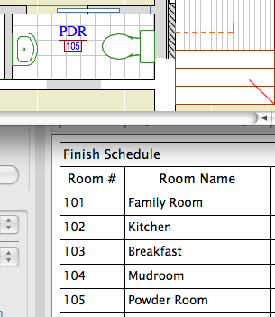
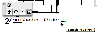
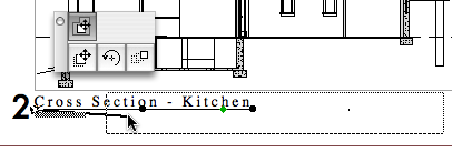
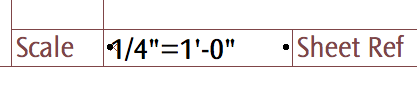
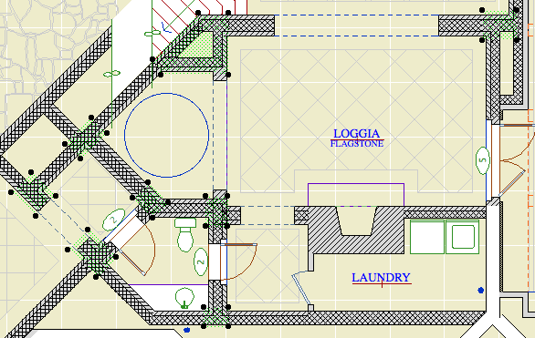
The object displays the short text...

Keynote in View

...and the schedule lists all the notes.

Keynote Schedule

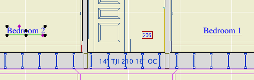
The only catch is that only floor plan elements can be scheduled; the workaround for this is to make sure any elevation keynotes are duplicated on a hidden layer in the plan.

This is super simple once you get your GDL friend to write you the object. No new tool, no add-on.

But it doesn't work due to limitations in Archicad. Only labels can display properties, and of course they display the properties of other elements and have no properties of their own. And labels can't be scheduled. Objects can't display properties, not even properties attached to themselves.

I expect Graphisoft finds the notion of attaching properties to annotations rather than building elements to be Not BIM. Respectfully, they need to get over it. (Or let us schedule labels, which I guess also Just Seems Weird.) This is an old, constant, high-ranking user wish, especially in the USA, and it is THIS CLOSE to being crossed off.

Allow objects to display text of their own properties, and we're done.

This object is a tool for removing slope distortion from angled details such as rakes. A big improvement over this.

More»

This is the current state of element schedules. All projects will have schedules for windows, interior doors, and exterior doors. Many projects will have finish schedules, which are schedules of zones.

Let's quickly review the basics of interactive schedules. In the scheme settings, there are criteria, which determine what elements will be listed, and fields, which are the information to be shown about each element. Schemes can be imported and exported as XML files.

Then there is the schedule itself, where you control the column widths, header content, and text settings. It is pretty WYSIWYG with respect to output.

In addition to making schedule output, schedules can be used to inspect and edit model information. More on that later.

More»

In Archicad 21 you can use autotexts in labels. Rather than describing an element in disconnected words, you can display the actual properties, attributes, dimensions, etc. of the element. Use Archicad properties and name your building materials, surfaces, and composites carefully, and you can get good automatic notes. GDL-scripted labels have long been able to do this, but it's an order of magnitude more convenient to have this built into the basic text label.

Generally, such associated annotations are better, because if anything changes in the elements the annotations change too. Think ordinary dimensions. An element and its associated annotations are one thing.

But my goodness they botched this for US users.

If you use (feet and) fractional inches for your dimension units, you can't use any dimensional autotexts in labels without looking like a hack. This is because autotext dimensions are formatted according to the calculation units preference rather than the dimension units. There are no fractional length unit options in the calculation units preferences.

Here are two simple dimension values. The wall thickness is a dimension and the fixture elevation is a label autotext. Archicad says with a straight face that one of them is a dimension and the other is a calculation. A calculation with no operators and a single term, apparently.

calculation
Doesn't everybody vary units within drawings? No, no one does.

Wait, here's a label that works.

This is the Archicad library's Elevation Label 21, a scripted label (no autotext) that has been available for years. (Like a lot of Archicad library parts, this label over-serves and you have to fiddle a lot to get it looking right, but it's functional and reliable.)

dimension
That's not so hard, is it?

This label is scripted to use the dimension units, as common sense would dictate. There are global variables for the calculation units too, so they could have this label use them, but it's not even an option, because that would be (is) ridiculous. If I wanted decimal units, I could just set the dimension standard that way.

Maybe in Archicad 22 they'll fix the Elevation Label to use the calculation units for consistency. (KIDDING!)

I don't know how this decision made it out of committee, and I'm sorry I didn't notice it earlier, but that usually doesn't matter. This is worse than How Could This Possibly Be What I Want, it's just carelessness that never got reviewed because it doesn't affect metric users. (But it's wrong there too.)

Why don't I care about the reason?

Because I'm a user, not a developer. My job is to make my projects work, and the developers job is to make the program work. I'm sure there's a reason for this situation, and it might be very interesting from a development point of view, but that's not my point of view. To a user, it's just wrong and needs to be fixed. (In all honesty, as an Archicad observer I'm curious about the reason, but it's not the user's role to care.)

And, the whole dimension and calculation units thing probably needs a do-over. It would be welcome to have units control at the level of the element (dimension, label) or schedule. An electrician might prefer that fixture elevation in fractional inches, for instance. This will become more important as more annotations become automatic.

PS, metric people: Sure sure, I'm with you but you're not helping.

This clever trick from Patrick May at 4dProof about labeling zones in section has two parts. The clever part is the lateral thinking of labeling things in the zones rather than the zone itself. The other part is the introduction of autotexts in labels in Archicad 21.

The lateral thinking part could have been discovered versions ago, you just needed to script the label in GDL because there was no label autotext.

So when I got done slapping my forehead I wrote a label in Archicad 20 which matches our zone stamp and the object we have been using to 'label' rooms in section. And while the label autotext is very handy, but, as always, GDL gives you more power and control.

First, let's review the clever trick. You can't label, or even detect, zones in section or elevation. What you can do is label a model element, and have the label state what zone an element is in. (Related zone condition is determined in plan. The elevation of elements and the height of zones doesn't matter.) Turn the pointer off, and you have a word which is the name of the room floating in the room. The label is live data - if you rename the zone, the section labels will be updated. And, you don't need to know the name of the room to label it.

These element types can report their related zone:
• Object
• Lamp
• Morph
• Beam
• Column
• Stair
• Wall, if zone boundary, with caveats

These element types are ineligible:
• Slab
• Roof
• Shell
• Wall, within zone
• Door
• Window
• Skylight
• Railing (AC21)

To label the room, you need to find an eligible element in it. In our projects, considering that not every room needs to be labeled, almost every room has a lamp, object (moulding, appliance, plumbing fixture, etc), or beam in it. If there are none of these in a room, I suspect the project isn't far enough along to be labeling rooms in section.

The main walls of the room, since they are usually boundary walls, are a good choice with caveats. There may be two (or more) zones related to the wall, so you need to be sure the right one is shown. In Archicad 20, sometimes there are two zones available and the label just ignores one of them. (This seems to be fixed in Archicad 21.) If the walls won't cooperate, you'll need to find something else to label.

Room names in section

The basics described so far also apply to labeling with autotext in Archicad 21. These are the additional features of this scripted label:

It precisely matches our standard for room names, including the fussy underline and the ability to 'stack' two-word names.

It can show the name and the number or both, and the font and size of these texts can be different.

It tries to help if you label something ineligible. If you label an ineligible element, there is no text to display. In this case the autotext label just sits there, blank and invisible. Go ahead, place a bunch of empty labels until you notice the pattern! The scripted label helpfully states 'something is wrong' in this case. (The two things that can be wrong are that the element is of an ineligible type, or it is not inside a zone. GDL doesn't offer the ability to tell these conditions apart, otherwise I would have the label tell you.)

If you are labeling zone boundary walls, you can switch between the two zones the label knows about. (Autotext only offers one zone and no way to switch that I can see.) There is a checkbox in settings for using the 'other' zone, and even better there is a graphical switch at the top of the text block. (It only appears for walls with zone zones.) Switching doesn't always help: Since walls can bound more than two zones, the one you want might not be offered. You'll need to label something else.

Update, July 7, 2017
Only the main properties (name, number, etc) of the zone are available to labels. Our zone stamp has additional parameters, such as an optional short name which can be shown in small rooms. These parameters aren't available to the label, so you can't use the short name for rooms that are small in section. In that case you can make the text size smaller or use the number instead.

I have tweaked the label so it behaves more civilized in the settings dialog.

Download

Graphic overrides greatly expand the number of ways an element can represent itself in different kinds of documentation. This means less redundant 'drawing', and more unity.

The RCP has long been a frustrating form of output if you're trying to minimize drawing. All the things that need to be shown are modeled, but Archicad has had limited facility to present these elements with properly modified attributes. In practice, 'properly modified' usually just means a dashed line type.

Now, with graphic overrides, we can choose any kind of element and say, draw it with a dashed line type instead of solid.

It follows from this that we probably need fewer custom object solutions that use the ceiling switch.

More»

Graphic overrides are a new feature of Archicad 20. They allow you to choose elements by criteria, and change their appearance attributes. The changes are grouped into combinations which can be saved with views.

Here's how to use Archicad: Build a model, and try to create all the documentation while doing the least amount of non-modeling. If you find yourself drawing something that you have already modeled, it must be because the thing can't be made to present itself in the appropriate way for your documentation. Archicad has always offered methods to help with this. A door can have a complex plan symbol, a simple symbol, or just an opening; it can have a schedule marker or not; or it can be hidden entirely. The same one door appears in 3D and in a schedule. One door, many appearances in documentation. This is unity.

Graphic overrides greatly expand the variety of ways that a single element can be presented. This means it is less likely that you will need to 'draw' an element you have modeled in order to get it to appear correctly in your documentation.

This feature gets at the heart of what Archicad is all about. It will definitely change a lot of working and documentation methods. If it doesn't, you are probably using Archicad wrong.

Since this is a major feature, it is impossible at this early stage to predict everything that will change. But I am getting a sense of what the categories of changes might be.

More»

Here is a massing model showing existing conditions and a proposed addition. It is mostly done with renovation filters, with a couple of tweaks from graphic overrides.

existing-new massing model

Existing is overridden with one surface, the light color in the picture. If you are OK with existing elements not having fills in elevation, you can leave this override on. If you want the fills in elevation, you need to turn the surface override off, and switch it back and forth manually. This setting can't be saved with views or filters. We really need per-filter renovation overrides.

New is overridden with a different surface, the red in the picture. New elements are generally shown, not overridden. So the surface override can be left on. It is currently the only active override setting for New.

There is a new renovation filter, 07 Massing by Status. Existing=override, Demo=hide, New=override. Again, in all other filters, New is shown.

These are the graphic override rules:

Site Green finds 3D elements (in practice, they are meshes with the occasional slab) on the layer C Site3, and changes their uncut surfaces to 'Grass - Green'. Graphic overrides happen after renovation overrides, so while the site has existing status, it is not shown with the white color.

3D Lines Match finds All Types of elements, and changes their Line Pen to a medium gray pen. (It's our pen 137 in the picture, the default pen 2 would be fine too.)

Glass can't be overridden within windows and doors. (This would require attribute-level graphic overrides.) If you want clear openings of any sort, you have two options I can think of:

One way is to use 'Filter and Cut Elements in 3D' to hide the doors and windows. This will give completely empty openings.

The other is to use a graphic override rule similar to the site/grass rule, where doors and windows are chosen to be overridden by a clear surface. But, all parts of the doors and windows will be clear, not just the glass.

This is a very simple label for duct elements made with the MEP Modeler add-on. It's intended for use with any simple duct type, including Straight, Bend, Take-off, and the Obstruction Fittings (as far as I can tell). I'm using it solely for straight pieces, since no one is fabricating anything from my plans - I just want to coordinate with the HVAC engineer.

For round ducts, the label reads '5" dia'. For rectangular ducts, it reads 'Width x Depth'.

All our ducts are sized in inches, so I'm using a fractional inch format for the dimensions. On the off chance that someone else might find this label useful, I've added a parameter so you can choose to have the label's format match the current dimensions format in the project preferences.

It was convenient to use Select All for the (straight) Duct Tool, then label them all with the Label Selected Elements command (Document -> Document Extras).

Duct Labels

Download

Until now we have done the electrical symbol legend as a hotlinked module of a story, where the lamp and object elements are placed in the floor plan within a table drawn with lines. This is a static resource, unless you break the module hotlink and modify it.

It is possible to create the legend using Interactive Schedule. The advantage of this is that it will only display the symbols that are actually in use. This makes a more compact, relevant, and readable table.

Electrical Symbol Schedule

The schedule itself is very simple. It only shows two columns. The first is the 2D symbol, which is a field/parameter of objects and lamps. The second is a custom parameter of our lighting and electrical objects - the parameter is 'desc' internally, and is called 'Type' in the settings. (A missing feature in most library parts is an ordinary name that can be easily listed and labeled. The object name usually doesn't work, and style options usually go by cryptic handles such as 'Style 1'.)

From here on I will say 'object' while I mean 'object or lamp'.

The schedule merges identical items into one. Remember that the IS only considers displayed information when deciding what is identical. So if the symbol and Type are the same, none of the other parameters matter - you will only get one entry. You have a surface fixture at 8'-0" and one at 9'-0"; they are the same to the schedule.

Simpler objects know what they are out of the box. Ceiling fan, duh. Some objects have options which change their identity. A recessed fixture can be ordinary, waterproof, a heat lamp, adjustable, etc. A smoke detector can be a CO detector, or a combination. The Type parameter should automatically respond to these details. The schedule will list separate items for each of these differences, because the Type field is different. The symbols will be appropriate for each difference.

The electrical switch object will always present itself as a pair of switches, one regular and one dimmer. This is so sets of two, three, four, etc. switches don't show up as separate items. GFCI switches are shown separately. (GDL folks: This is done by drawing a specific case of the symbol when the GLOB_CONTEXT is a schedule. In the future, but starting now, GLOB_CONTEXT is deprecated and you should use GLOB_VIEW_TYPE=9 (Calculation) instead. Since I'm still maintaining our AC18 Library, I can't implement this change yet.)

I had to replace the ceiling fan symbol so it would fit in the same cell height as the others.

Again, when you have your own library, you can do whatever you want.

Criteria
Electrical Schedule Criteria

The criteria look more complicated than they are. It's just:

• Objects and Lamps

• On any electrical fixture layer

• But not on the Footings story, because that's where the old legend is placed

• And not part of a hotlinked module. Delete this criterion if the module is not covered by a separate project, and you want to schedule the module's fixtures.

Fields
Electrical Schedule Fields

The fields are only two, as described above. The 2D symbol and the Type:

The schedule is saved as a view in the Schedules folder, alongside the window and door schedules. It should be placed as a drawing on each electrical sheet.

This is a new approach to showing openings in reflected ceiling plans, using a modified plan symbol rather than an blank opening. I haven't put it in the template yet, and it may not be required or appropriate for every project, but it is better overall. The biggest limitation is that in order to use it you have to use our doors and windows almost exclusively. This doesn't bother me much.

More»

Short Name
So that a zone can be shown with an abbreviation in the plan where there's not enough space, and with the full name in schedules where abbreviations look awkward.

Put the abbreviation in the Short Name parameter. If the parameter is empty, the full name is used in plan.

Another idea would be to hard-code standard abbreviations for typical room names.

What happens if you revive an ancient project and you want use the layout structure of the current template?

More»

The finish schedule is an element schedule of zones. You need to read that link if you haven't already.

More»

Sheet A4-1

The reflected ceiling plan is a universal drawing type that Archicad simply does not handle very well. We took a medium-size step forward in Archicad 11 with addition of the 'Ceiling Plan' model view option for GDL objects. This allows object developers to make objects that draw themselves differently whether the 'Ceiling Plan' or 'Floor Plan' setting is active. But this switch only applies to objects, and beams, slabs, etc. don't know you want a different linetype when they're overhead as opposed to on the floor. Hopefully, this switch will soon apply to all elements, and we will have dedicated attributes for 'Ceiling Line Type', 'Ceiling Pen', and 'Ceiling Cover Fill'. I have wanted this for a while.

In the meantime, the RCP still demands a lot of tracing of modeled elements. It's better than it used to be, but it's still one of the least unified drawings.

What shows:
• Walls
• Ceiling trim and finishes
• Ceiling fixtures including lights, fans, and mechanical fixtures
• Floor elements, including deck edges, stairs, counters; traced with a dashed line

More»

Top View Drawing
In the site plan, the top view of the house is a separate drawing.

Why? The site plan is generated from the first floor. The roofs are only seen in their entirety on the roof story. The only way to get the roofs on the first floor is to draw (trace, copy/paste, whatever) them. We don't like drawing things. Especially things that can draw themselves, especially things we have to keep checking in on to see if they are drawn properly. We want a top view drawing that maintains itself like any other model view.

There are two ways to do a top view so that it remains live: A plan view from the roof story (like the roof plan itself), or a hidden line top view generated in the 3D window. I think the 3D method is better. The 3D view can show elements of all stories, while the roof plan will use the story settings of individual elements. There's no issue of display order in 3D. A roof plan drawing would have the advantage of generating a little bit quicker, but that's not enough to change my mind.

The templates are set up with a view in the 3D views folder called 'Top View'. You might need to change the scale of this view; obviously it needs to match the scale of the main site plan. The other settings are:

• Layer combination: x Shoot Roof Plan Top View. (Update: I changed the name for clarity.)

• 3D Projection Settings: Top view, azimuth=270 (Camera at bottom).

• 3D Window Settings: Internal Engine, hidden line, vectorial hatching off, shadows off, transparency off.

The trickiest part about the two-drawing approach is aligning the top view with the main site plan. For some reason, we don't get the snap points (midpoints, e.g.) for lines within drawings, so we can't line up a roof edge midpoint with a footprint line midpoint. Fortunately, for most purposes, good enough is good enough. Zoom in and eyeball it. Make it look good. Remember, the dimensions will be to the footprint, which is drawn precisely in the main site plan drawing. If you do need a precisely placed top view, you'll need to place some temporary alignment elements on the first floor.

Make sure the top view's drawing element is set to have a transparent background. The pen set of thew drawing should be Layout 1/8", which turns the heavy lines a little less heavy.

The new templates for Archicad 11 have an improved fill pattern for concrete in section, Concrete Random. I got it from Andy Thomson.

Concrete Fills

As you can see it has more size variety in the specks and is more random overall.

I've chosen to leave the old fill in place with its attribute ID unchanged. Why. To avoid potential conflicts when merging project stuff that has the old fill.

For new projects, this won't make any difference. All the composites, favorites, and standard details are set up. For running projects, it means some work to deploy the new fill.

So here's a pretty good list of everywhere you have to look to fully modify such a common attribute:

• Slab elements, including 'slab' slabs and footing slabs. In the 3D window, do a Find & Select for slabs of fill 'Concrete Lightweight'.
• Wall elements. In the 3D window, do a Find & Select for walls of fill 'Concrete Lightweight'.
• Other elements: A roof in the role of a ramp? A mesh for a slab sloping to drain?
• Favorites for any of the above need to be redefined.
• Composites for walls and slabs. Favorites with composites don't need to be redefined.
• Fills in drawing windows, primarily details, but including 'Drawing' sections, elevations, and interior elevations. There shouldn't be many of those.

The fills in the Material Symbols and assembly modules are a management responsibility.

It sounds like a lot but it really isn't, and the new fill looks a lot better.

You can use Attribute Manager to get the fill from either of the zTemplate 11 folder's .tpl files. Overwrite, not Append. (It will overwrite 'Concrete Structural', which is even lamer-looking and we never use it.)

(1) A custom profile for modeling and (2) an object for annotation.

Profile:

Soffit profile
In the profile editor
• The shape is that of two fascia boards with a reveal of 1/4" below the soffit board.

• The horizontal stretch extents are inside the fascia board reveals. This way, when you adjust the overall width the fascia thickness will be unchanged. Similarly, the vertical stretch extents go from the top to the underside of the soffit, leaving out the reveal.

The custom profile tech only allows you to stretch one dimension horizontally and one vertically. You can exempt parts of the profile from stretching, but you can't stretch them independently. If you want a different reveal depth or fascia thickness, you'll need another profile.

• Profiles can stretched bigger, but not smaller. (I call this a bug, but what do I know.) Any profile you intend to use with varying dimensions needs to match or be *smaller* than the smallest case you have.

• The templates have two profiles, Coffer Beam and Coffer Beam Half. Both are 4" x 2" which should be small enough. The half version has the fascia on only one side and is meant to be placed along a wall.

Remember that profiles are attributes, so they're within the project file, so you can edit them without messing up anybody else. And: You can use Attribute Manager to bring profiles into the current project from the templates.

Here is a sample condition at 1/4" scale, no detail added:

1/4 scale soffit

At higher scale, we need to add detail:

3/4 scale soffit

Object: Soffit Beam Section JM10

Location: 06 Wood & Plastic / 2D Wood

The object fits within the profile's perimeter.

Height and width of the object will match that of the beam itself.

• Parameters for Fascia thickness and reveal.

Crown Hgt sets the point at which the pen switches from the object's cut pen to the Separator Pen. In practice this height should meet the bottom of a crown object placed against the beam, which will maintain the heavy outline.

Crown height stretch

• The Half option uses one fascia board to work with the half version of the profile.

Commentary:

We build one model. We take views of the model and annotate them as needed. We will take views of the model at various scales. Scale is fundamental to architectural documentation: As we look closer, we see more.

Yet Archicad lacks any meaningful automatic scale sensitivity, except that written into objects by people who want it such as me.

In this example, see how the crown objects draw themselves as empty blobby things at 1/4" scale, but they're detailed shapes with proper fills at higher scales. The roof, slab, and beam elements, not so much. (Archicad library objects, not so much either.)

Since we can't get conventional AC elements to detail themselves according to scale (yet, I hope I hope), we need to build a model that can accommodate the detail we need to add. This is the idea behind something like the Stud Wall Detail object. The wall is empty, and we place the object in the viewpoints that need it.

The soffit detail described here has always been tricky. If you approximate the beam with a rectangular model, it's difficult to manage the reveal without masking. It's easier to add 2D detail than to subtract modeling.

A custom profile allows us to handle the cased beam in the "Empty Fill +" fashion we are accustomed to with walls, roofs, and floor decks.

Superseded by this.

Sheet A2-1
Everything I can think of about sections and elevations. Updated for AC10.

More»

Automatic titles are not new to 10, but title objects are new, and now that they are objects, we can use them, which is new.

A drawing title is essentially a marker for a drawing element. Like section markers, detail markers, symbol labels, and door/window markers, you choose the title from a popup menu rather than from an object-type browser.

Drawing title list

As with all markers, there's no way to restrict the list. It shows all the loaded drawing titles, and it's up to you to pick the right one.

Elevations, sections, site plans, and details should all use automatic titles. Plans are the only drawing which has an object (Plan Title RND10) in the window. PDFs placed for notes ordinarily shouldn't have a title. Scanned details might, it depends.

Since the title and its settings are part of the drawing element's settings, you can change them in groups using the Drawing Manager. (Note: You must have a layout as the frontmost window to do this; otherwise the title tab is grayed out.)

Drawing Title RND10a is very similar to Drawing Title RND9a. There's a couple of 10-specific changes:

• By default, the title uses the name of the drawing (which should come from the name of the view, which should come from the name of the window). You can put in a custom text under the 'Title' tab in the drawing settings dialog.

• Titles don't have a length parameter like a regular object. So the Length parameter controls the length. You would normally adjust this graphically:

Title stretch

The length still has a minimum equal to the title text length.

Again I have to apologize for issuing a '10a' revision. There was one issue with Drawing Title RND10 that I couldn't fix in place. That title would appear right on the corner by default. The new one appears 3/8" below the corner, which makes it easier to move the title as needed. Note the 'move marker' palette button:

Drawing drag

And, full disclosure, I broke the minimum length thing, but now that's fixed.

UPDATE 2007-12-11:

• You can set the Orientation of the title. You can have the title rotate to align with the Drawing (default), the Layout, or a Custom Angle. Use the Layout option to keep the title horizontal when you rotate a drawing. This is optional, and it's not always right. For example, if you rotate a wall section to fit on the sheet, the title should rotate too. I can't think of a purpose for Custom Angle, but it wasn't hard to put in there. If you do ever use it, the angle is graphically editable.

• You can choose a manual scale from a list. Leave the field empty to use the drawing's true scale. This is usually correct. To show no scale text, choose 'blank' from the list. You need to set a manual scale for a scanned detail PDF; now you can choose it from a list.

(Heavily revised for AC10, though still a little clunky.) This is the standard workflow for issuing SK drawings.

More»

Location: 01 General / 5 Title & Layout

SK Hints

Very, very simple. A text showing a standard scale, which you can choose from a list. The primary use will be placement in the SK layouts' scale field.

Why? I don't like typing scales. And no, it's not easy to get the scale of the placed drawing automatically, though it should be.

Use it for SK addenda.

The templates have a fax transmittal as part of the layout book.

More»

Date Formats
Options
Location: 01 General / 1 Graphic Symbols

A text object for writing the date.

If Auto Update is on, the date will be read from the system. (Tip: turn it on and then off to get today's date while keeping it from updating by itself tomorrow.) The Year, Month, and Day can be set manually using the pulldowns.

There are a lot of Date Format options. I've tried to cover all the conventions that I know of.

Any of the formats with a separator character will use the character given in Date Separator. You can choose from the list or make something up.

Two-Digit Day will zero-pad single digit days.

Day of Week can be on or off. If it's on, it will be read automatically along with the rest of the Auto Update. It will not fix itself for a manually set date. (It doesn't know the 30th is a Tuesday.) The Format of the day of the week can be long or short. Note that the list will always give the short form. The day of the week can be followed by an arbitrary separator, where the default is a comma.

You can add Leading or Trailing Text.

Text Formatting: All the usual suspects. Font, size. (You can choose mm or points to define the units.) Bold, italic, underline. The object can be anchored by any of the nine typical text block spots, using the Horizontal and Vertical Anchor parameters. You can have a Background Pen and the Outline Pen. Setting either one to zero turns it off. Finally, you can set the Padding between the text and the background/outline polygon. (This uses the same units option as the text size.)

Non-locals who would like to try it out can download it here.

Smarter cleanup please.

9 Patches

Archicad 10 offers the ability to place a live drawing list, which will automatically list the sheets in the set. It works, for the most part, with a little tweaking.

More»

Background: Navigator Theory

Issue: You need plumbing (or mechanical, etc) plans, which aren't set up in the templates.

This is a piece of cake.

More»

Archicad 10 finally gives us the ability to place PDF files in layouts, as well as other project windows.

PDF-in-layout will become the standard method of placing non-Archicad info in drawing sets. Any file (Word doc, spreadsheet, etc.) can be saved as a PDF via OS X's Print PDF facility. In the current templates, the abbreviations and general notes are PDFs. It's the new stickyback.

Since you can place PDFs as model windows too, you may find it more convenient to use PDFs for topo surveys, plats, and the like.

PDFs become drawing elements. Since drawings are polygons, you can crop the PDF however you like with the pet palette.

There are several methods for placing PDFs, in rough order of convenience:

• Drag the PDF file from the Finder into the Archicad window.

• Use the Drawing tool. Click where you want the file to land.

In a layout window, you get the 'Place Drawing' dialog. Choose 'External Source' and then 'Browse'. Navigate to the file you want.

In a model window, you can only place an external drawing, so you immediately get the Open dialog, where you can choose the file.

• File -> External Content -> Place External Drawing. Select the drawing in the dialog box. (Least convenient method IMO.)

Whatever method you use, you can only place one page of a PDF at a time. If the PDF has multiple pages, you will get a dialog box where you can choose the correct page. To place multiple pages requires multiple drawing elements.

Since they're drawings, they can have titles, but they usually shouldn't, right? Make sure the title is set to 'None'.

Like all external drawings, PDFs will be Manual Update by default. If you modify or re-save the PDF, remember to update the drawing. I don't recommend setting external drawings to Auto Update.

If you take the project file off the network (home, e.g.), you will get a warning that the source file for the PDF can't be found. This is usually not a problem. The drawing will still appear, you just can't update it. When the project is reunited with the network, the warning will go away, and you can update the drawing as needed. (Note the similarity to Hotlinked Module behavior.)

Location: 01 General / 1 Graphic Symbols

A custom drawing title object for plans only. It's very similar to the old Drawing Title RND 9a.

As you know, in AC10 we use the new automatic drawing title marker objects. All drawings except full size plans should use the automatic titles.

Why do plans still use an object? Because we want the titles to stack through the sheets, and the best way is the multi-story feature of conventional objects. There's no easy way to align elements across layouts.

Since we're sticking with the object for plans, and not using the object for anything else, I decided to optimize the object for plans, so here we are.

Story Setup
It knows what kind of plans we usually have. (Architectural, RCP, Electrical, etc.) It knows roughly what stories we use. You tell it what kind of plan it is (it can be custom), and what stories you have, and what the stories are called. It places the appropriate titles on each story.

In the templates, there is one of these guys for each plan. In setting up the project, you need to set up the plan titles. For example, turn the attic off if there's no attic. The best way to do this is all at once: Turn all the note layers on, select all the title objects, and change their story setup.

The different names for a given story are all hooked together, so if you turn 'Main Level' on, 'First Floor' will switch off.

Place the object on the lowest story that is in use. If that's the basement, turn 'Basement' on. If not, turn it off and 'First Floor' will take its place. Etc.

After some experimentation, this is the best method I can find for using external, standard details. It definitely has room for improvement. The biggest improvement would be for AC to allow detail markers to reference external drawings. It's a huge hole in the program that has to be fixed. In the meantime this isn't too bad.

The executive summary: Copy details from projects and clean up their layers and other attributes. Place the details in a central PLN file, one per story. Or, draw them from scratch in the central PLN. Publish modules of the details. Hotlink or merge the modules into detail windows of running projects, and use detail markers to refer to them normally.

In this example I'm talking about the wall and other assembly types. It could used for any standard details you would like to share. Also, we will use this as a standard method beginning with AC10. In the meantime, everything here which concerns placing detail modules can be applied to current assembly modules at 3 Resources / Modules / Assembly Types.

More»

It would nice to have standard details in one place, where any project could use them with no need to redraw anything. These would be standard assembly types, foundations, flashing, etc.

You can place views from any number of external project in a layout book in 9 or 10. The trouble comes in when you want to refer to the external drawing with a detail marker. Even in 10, this is still not possible.

So we have to consider a couple imperfect alternatives.

• Maintain modules, one for each detail. Merge or hotlink the modules into detail windows within the project. Refer to the internal detail drawings normally.

If you hotlink the modules, they can be truly standardized, with any changes distributed to all projects by updating hotlinks. The drawback is the module reference warning if you take the project off network. No harm, just hassle. (You could choose to break the hotlink, which would leave the detail intact, but it wouldn't be connected to the original.)

As an alternate to separate modules, you could place all the details in one project file, with one detail on each story. In this case, merging is not an option. You would hotlink the stories and optionally break the hotlinks.

Then you could use Publisher to create modules if you wanted them.

The one-project method also makes attribute management easier. It's important to rigorously control attributes so you don't 'contaminate' the current project.

Using hotlinks to the detail project stories presents a problem: You can't insert a story without breaking the links in projects. Ouch.

• Use external views directly, even though the referencing doesn't work. You would need a fixed ID, specific to the detail, which would appear in a drawing title object in the detail, and in the detail ID in the project. These IDs would bear no relationship to the sheet. Weird.

Conclusion:

• Create the details in a project file, one on each story. This is simpler generally and helps with the attributes.

• From this project, publish modules of the details. Then the modules themselves are hotlinked or merged. The detail project becomes an administrative resource; users don't interact with it directly. The stories can be managed for the convenience of the 'detail administrator'. Whenever a detail is added or changed, republish the modules.

• Hotlink or merge the modules into project detail windows and reference them normally.

align symbol
Check out how the arrows don't step on the text.
Location: 1 General/01 Graphic Symbols

The alignment symbol. Slightly improved from the JAM8 version: You can have more than two arrows, up to a total of eight. That should be enough. For the extras, you can turn on Equal Spacing, or locate each one individually.

In framing plans, it's often helpful to show the walls on stories below with dashed lines. Especially roof framing. Well how do you do that.

More»

I'm still not totally comfortable with the SK routine. For example, if you place the SK title block in the plan, you run into trouble when the SKs overlap. And it's a pain to set the scale when using the title block within PM.

Here's what I'm doing as of now. It probably still can be improved, and as Vassos starts needing revisions I'll probably make further progress. This shouldn't be interpreted as standard right now.

Create a new layout in the SK folder. Use the SK Master, the one without the title block. Name the layout what you what to print on the SK. The autotext in the title block object will render the layout name.

Set up the title block in the AC detail window with the date, sheet ref and scale. Import the 'xSK Title' view into the layout. (Not the Master Layout.) Tip: In the Navigator, copy the title block drawing from the 'SK Blank + Title' Master. (Drag while holding Option.) Make sure you update it.

Select the title block drawing and explode it. That turns it into 2D elements. When you change the title block in AC later, this layout won't care.

Import the relevant view(s) to the SK layout. Tip: Copy the views from wherever in the set they live, and update.

Interlude: Drag-copying in the Navigator. You can easily move drawings between layouts by dragging them in the Navigator. If you hold down Option while doing so, you will make a copy. You can be sure you are copying rather than moving when you see the green plus-sign circle.

Once the drawings are in place, go to drawing usage, select them, and click 'Break Link'. This basically turns them into PMKs that are embedded in the layout book. In drawing usage their status will read 'Embedded'. When the views from which the drawings came are updated, these PMKs will be untouched.

The combination of exploding the title block and breaking the views' links means that the SK layout will stay as it is, whatever else changes in the project and layout book.

The SK thing is a tricky area, since AC and PM are not naturally inclined towards revision control in their current state.

With the detail tool and a well-developed model, trim details can be developed pretty quickly. The oddball is rakes, since there's no way to cut a non-plumb section. You need to take extra steps to correct the distortion arising from cutting through sloped elements. A conventional resize won't work, because you can't restrict it to one axis.

The trick is to create a patch and then adjust its vertical dimension.


The goal.

1. Marquee the area you want in the detail and create a patch.

2. Figure out the conversion factor. There's at least two ways to do this, I like the first one.

a. SIN(90-RoofSlope). Example: 10/12 pitch is 39.8056º. SIN(50.194)=0.7683.

b. (True thickness of roof) divided by (plumb cut height of roof). These values are readily available in the info box. Example: A 10" roof at 10/12 pitch has a plumb height of 13.017". 10.0/13.017=0.7683. Tip: Much easier if your working units are decimal.

Four decimal places is fine. If the factor is greater than one you've made a mistake.

3. Now you can either a) drop one line into the patch's 2D script, or b) calculate the adjusted height of the patch and change it in the settings.

3a. Open the patch object. At the top of the 2D Script type:

MUL2 1, [ConversionFactorFromAbove]

For the 10/12 pitch, that's:

MUL2 1, 0.7683

Save the object.

3b. Multiply the 'natural' height of the patch by the conversion factor. Select the patch, and put the converted height in the Y field.

Either way, you're squeezing the patch so the vertical dimensions of the elements are right again. Horizontal is unchanged.

4. Create a detail. I recommend an independent detail, since the source view data for a detail generated from the window will never be right; it will be pre-patch distorted, and you'll have to delete all of it.

5. Place the patch object in the detail window. Tip: Cut and paste it from the section window. You don't want it hanging around the section anyway.

6. Select the patch and explode it (Cmd+=). Now you have 2D lines and fills as if you had generated the detail directly. Except: All the elements are of one big group. Also, there's an 'Air Space' fill element in the shape of the patch, which you don't need.

You can trash the patch from the library if you wish. It is no longer needed. On the other hand, it doesn't take up much space. Whichever.

Obsolete. Referencing in AC10 and later doesn't work this way.

It sure is nice the way detail markers know where their drawings are placed. It sure would be nicer if we could as easily refer to any placed drawing. If you could place dynamic drawing and sheet references in section marker objects, and call out enlarged plans, and write notes of the form, "Do this like this, see detail A3-5/12." And since you can't place details in detail windows, use an object detail marker there.

Well, you can refer to any placed drawing. But I wouldn't call it easy. In fact, I think this is the most annoying worthwhile thing in all of ArchICAD.

Here's how. We'll do the drawing number first.

Import the drawing to a layout.

Right click on the drawing (in the layout or in the tree) and choose "Set as Autotext Reference".

Activate the text tool. Start a text block by double-clicking. In the text editing area (at the cursor), right-click and choose "Insert Autotext for [DrawingName]" -> Drawing Number. This results in a blob of gibberish like "< DRAWINGNUMBER_R ><9BEA5D4E-8700-11D8-8AA9-000A95A7B33A>". Copy this. Tip: Cmd+A works to select all while editing text. So, Cmd+A, Cmd+C.

Return to Archicad. Open whatever it is that needs the reference, e.g., a detail marker object or a text block. Paste into the appropriate field or location.

Of course, you usually need the layout number too. Return to PlotMaker. You should see the open text block as you left it. Delete the DRAWINGNUMBER stuff. Repeat the process, this time choosing "Layout Number". Cmd+A, Cmd+C, Back to Archicad, Paste.

A detail marker will look like this in Archicad:


The gibberish bits resolve themselves in PlotMaker, giving the location of the drawing you set as autotext reference in the beginning.

Everybody knows this, right?

Do not use the "Cloud" objects in the Archicad library. They are the worst objects in the world. Update: I killed these with my bare hands. They're gone and you needn't fear them any more.

Clouds should be drawn with a closed spline using the "cloud" linetype. The only glitch is that sometimes the cloud will be inside out when you are done. If this happens mirror the cloud, or, if the shape is non-mirror-friendly, draw the spline again, in the opposite direction. Sometimes the spline doesn't quite close. Pretend not to notice.

For the triangle, use the object Character+Shape JAM8 Shape Tag JM9. The number comes from the ID.


Bad cloud. Looks like a chunk of foam rubber from an AirTran pillow. Also missing marker.


Pretty cloud, reminds one of heaven.

Read this. OK good.

I only save one PMK from AC*; the perspective drawing. Here's how to do it in publisher.

* The PMKs for schedules and such are created in PM.

More»

Especially on the roof framing plan, it helps to dot in the walls below. It's easy and quick.

More»

The automated window/exterior door schedule.

More»

All Entries | 1 | 2 | 3 | 4