On Land

Environment Information
At Rill Architects we run ArchiCAD on macOS. If you work at Rill, this is your stuff. If you don't, but you work in ArchiCAD, you may find something interesting. Anybody else, I don't know.
RSS
Sheets Archive
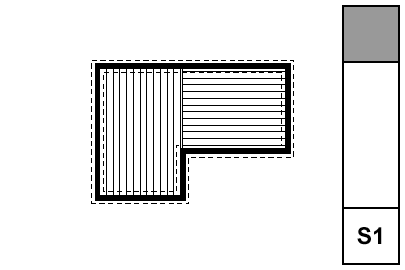
Sheet S1
Rules for framing plans. Foundation plans are slightly different. Roof framing plans are very similar. I'll have a separate note for them. I wonder what the difference between 'slightly different' and 'very similar' is.

• Walls. Display of walls is controlled by Display Options. The 'Cut Fills' option should be set to 'Separators Only'. The walls will be clear, with lines at the separators; for example, between concrete and stone. Use the 'S' Display Option Combination.

• Bearing Walls. To show a bearing wall, draw a fill on top of it. This is a non-associated, additional element. Use the fill '*Masonry Block', with a background pen of 50. Use the layer +S Struct Note. So: Walls are clear, except bearing walls, which are shaded.

• Rafters & Joists. Fill elements of the fill 'Joists 16OC' or 'Joists 12OC'. If you need other spacings, you need to make more fills. The fills go on the layer S Framing, which only shows in the framing plans. Rafter and joist placement is diagrammatic.

• Rafter & Joist Labels. Object 'Joist Note JAM9'. With the joists shown as fills, you don't need to show the extent in the note object, although it has that option.

• Beams. Beams should generally be modeled and labeled in sections. Use the objects Wood Beam JM9 and Steel W Shape Beam JAM9, etc. Most beams should be on the layer S Beam, which shows in section. If the beam is just used as a note, place it on S Framing.

Beams can reference their calculations by use of the ID tag in the objects.

• Annotations. All annotations should go on the layer +S Struct Note, unless you want an annotation to show in the foundation plan simultaneously. In that case, use +S Note All. Use a background of pen 91 on text blocks to make them readable when placed on fills.

• Structure Notes. Loads, criteria, etc. are part of the General Notes PDF. Specific notes can be added to the plans using text blocks.

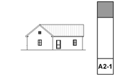
Sheet A2-1
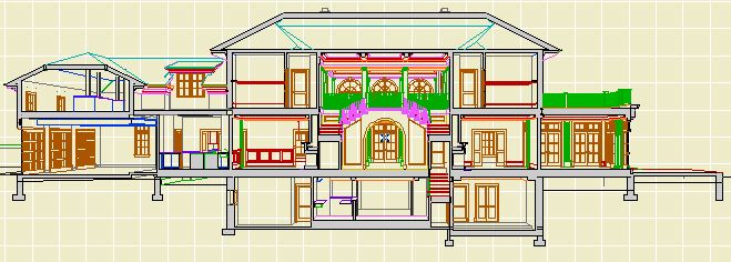
S/E Status (Model/Drawing). It is just really strongly recommended that all building elevations and sections be model views. Developing model sections is a little harder than elevations, but anyone can do it with practice.

I usually keep S/E's set to Auto-rebuild.

S/E Element Placement. Marker ends should not extend too far beyond the building itself. Our section elements go on a non-printing layer, and we use a separate object to show the section locations in plan. This is because it is difficult to reconcile the extent of the cut with the desired graphic presentation of the markers. That is, To get the markers looking nice you need have them much more extensive than is required to create the view itself.

Cut sections using the section marker Plain Section JAM9. This simple marker just shows the ID and a flag to indicate direction.

Elevations should be as close to the building as possible; the marker should be stepped where necessary to achieve this. Watch out for eaves and gutters.

Sections often require a lot of tweaking to get them to cut through interesting/clear/consistent stuff on all stories. Watch for undesirable effects of stepping with respect to roofs. Where a section cut is perpendicular to a roof's slope, try to avoid stepping the section within that roof. If you can't avoid it, discontinuities in the roof can be patched, but the patch becomes a maintenance issue if you edit the S/E element again.

Section depth should be minimized in order to improve performance. The depth should reach only the most distant element you want to see; usually it's a ridge or a chimney. Infinite depth sections should never be used. Zero-depth sections come in handy sometimes for generating details, but building and wall sections should always have some depth. Section depths are typically off in display options; toggle them using Karl's marvelous add-on.

Layers. All annotations go on the layer +A Arch Note Reg Scale. This includes text, arcs and splines used for leaders, and notation objects. All added 2D work should go on +A Misc Line, but this is not a critical issue. Since S/E windows usually only generate a single view, layer discipline is not as important as in the plan. You should, however, make consistent use of the Arch Note layer, to maintain the option of turning the notes off to display the S/E image by itself.

Vectorial hatching.

Elevation (and 3D) hatching is generated by the 'Vectorial Hatching' setting of the material in Options -> Attribute Settings -> Materials. The pen of the hatching should typically be 150, which is light gray.

Display of the hatching is a setting in the model tab of the S/E element itself. Hatching slows down generation considerably; in typical use it should be off. Before publishing, turn the hatching on for all the markers by selecting all of them and checking the box in the info box. The hatching switch setting is not saved with views, which is too bad.

Unwanted lines.

Ugly bits which are complex can be patched. To hide simple cases of a few unwanted lines, use a fill which matches the vectorial hatching of the elements involved (shingles, stone, etc.), and has an opaque background. For blank walls you can use a solid fill of a white-printing pen. I use 80, which is purple, so I can see the areas I've masked. Masking fills and patches should go on the layer +A Misc Line. The use of masking elements becomes a maintenance issue.

Rendering of depth.

Foreground elements should be outlined with a heavy (5-weight) polyline. There is no reliable way to do this automatically, it's tedious. One tip: for symmetrical building parts, outline one half and then mirror. Another: Outlines can often be copied and pasted to the opposite-facing elevation and mirrored across the origin.

Use Marked Distant Area where appropriate. When using it, check 'Use One Pen' and use pen 30. Pen 30 is gray in AC and 1-weight black in PM. You need section depths on in display options to edit the MDA depth. Don't forget the shortcut.

When you combine outlining with MDA, you get three levels of rendering: Fills on and outlined, fills on with no outline, and fills off.

Model pens. Except for walls and objects, elements are drawn in 3D with their floor plan pens. Walls have a dedicated 3D pen, which should be a 3-weight. (Typical walls are 13.) Objects can have a separate 3D pen, either as a parameter or hard-coded, this will vary. It is a long-standing wish that all elements have a separate 3D pen.

The ground. The ground mesh section settings should be: Fill='Air Space'; Background pen=91; Cut pen=6-weight. (I like green land, so 36.) These settings give an invisible fill with a heavy ground line. The bottom and side lines of the mesh should be obscured by the object Grade Mask JAM8, which goes on the +A Misc Line layer.

Annotations.

Elevation notes. The main materials and building elements should be noted. This includes wall finishes, trim parts, decorative columns, panels, railings, chimneys, etc. To align the notes, use the object Note Column JAM9, in the drawing tools folder. Notes on the right side should be left-justified with the leaders starting at the first line. Notes on the left side should be right-justified with the leaders starting at the end of the last line.

It is permissible to fully annotate one elevation on each sheet, and then only point out unusual features on other drawings on the same sheet.

Levels. Use the object 'Elev Marker JAM8'. Elevation views should show the Z-height of each story. It is helpful to draw a dotted (not dashed) line through he elevation at each floor level. Dotted lines need to be heavy in order to be visible; use a 4- or 5-weight. In sections, levels should be should be shown for ceilings as well as floors, and for interior floor level changes (such as garage slabs). Level objects will auto-display their Y position, which is the height. They should be dimensioned to show the relationships among them.

Knee wall heights should be dimensioned in section.

In sections, unusual ceiling or floor conditions may be labeled with Slab Elev JM9. Examples: Lowered ceilings in small rooms, a stepped slab in a theater.

Roof pitches should be noted in section and elevation with the label Roof Slope JAM9.

Doors and windows should be labeled with Door-Window Label JAM9.

Structural members in section should be labeled with Description JAM9. Joists are shown 2D-only using 'Joists Sect 2D JAM9'. Our standards don't support modeling the joists.
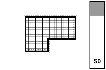
Sheet S0
The foundation plan shows the foundation walls, footings, slabs, and related annotations. Everything that touches the ground. It can be combined with the first floor framing, but an independent foundation plan can give more information with less clutter. The layers, layer combination, and views required are included in the templates.

• What Shows.

• All plan walls, A Wall Ext, A Wall Int, S Wall2.

• Steel columns which rest on footings, S Col Steel. Other columns remain on S Column.

• All footings, S Footing.

Framing plan layers which should be hidden in foundation plans: S Beam, S Framing, S Column, +S Struct Note.

• Annotations.

• Foundation dimensions. It should be possible to use the foundation plan to stake the project. When using a foundation plan, you should only have architectural (interior) dimensions on the A1 basement plan.

• Wall and footing sizes.

• Dimensions to all columns.

• Graphics and notes describing all slabs and their reinforcement. Elevations of slabs to project zero. Use fills to show reinforcement. Use a background of pen 91 on text blocks to make them legible when placed on fills.

• Detail markers calling out wall types and other relevant details.

Annotations belong on +S Foundation Note. Annotations which also show in the framing plans belong on +S Note All.

The foundation plan is typically generated from the same story as the first floor framing, so it requires a separate layer combination, S0 Foundation Plan. The display option combination, S Foundation, differs from that of the structure plans only in that the cut fills are Vectorial Hatching instead of Separators only.

The foundation plan's sheet number should be S0 (zero).

SK sheets are the official format for issuing corrections, clarifications, changes, and other additional information after the construction set is issued. SKs become part of the construction documents, and should created and maintained with the same care as the big sheets.

Use an SK sheet whenever you have to issue document information between official revisions. Revision sets should be updated to include the SK information since the last issue. For geometry taken directly from the model, this will take care of itself via the traditional view updating process. Scanned drawings and other non-project-file info must be placed on an appropriate big sheet, in addition to the SK layout, so the next revision is complete.

We have developed a special title block for a letter size sheet, Title Block SK RND81. It enables you easily to create an SK sheet out of any geometry in the project.

The preferred method of putting out SKs is PlotMaker, using special layouts within the main CDs layout book. The layout book will automatically number the SKs as they are created, and keep them in one place for safety and organization. You can also import scanned drawings into the layouts, so that hand drawings can be maintained consistently with the rest of the documents.

It is possible to simply place a SK Title Block in Archicad, marquee the SK, and print the marquee area. While this method is quick, it does not create a permanent copy of the output, nor does it maintain your numbering. In addition, printing from Archicad does not have the same quality as printing from PM, since the colored pens have to be turned grey.

See also:
Title Block SK RND81
Getting the SK Layout Tools into Current Projects

Detail sheets look nicer with a grid. The grid also encourages us to think about how details align, and forces us to be economical with the space we have for annotaions. Also it's standard practice.

The grid deployment has two parts: The grid module object, and the Detail Sheet master layout in PM.

All details should be developed with the detail module object. Place it before doing any annotations, so you can use it to align the notes. Most details should need only one grid cell. For larger details, stretch the object to an adequate extent.

The grid is designed to fill the standard title block. The grid itself must be drawn in PM. To make this easier, detail sheets have a special master layout with a drawing showing guidelines for the grid. The drawing also has hotspots at the cell corners for snapping the details into place. The lines must be drawn in PM in order to accommodate details of more than one cell. The lines should be drawn with a '3' weight pen.

The grid drawing exists in the project templates in three detail windows, one for each sheet size. Like with the title block details, the unneeded ones can be deleted.

Wall sections need not be placed on a detail grid, although you can place a wall section on a detail sheet if you have space. Better than making a new sheet for just one section.

Details' drawing titles should use the 'Medium' text size setting.

This is obsolete big time. More here.

The roof plan has to be drawn. Sigh.

Update: I changed the recommended line weights, making them lighter. I think this will make the structure plan read better.

More»

Draw an enlarged plan of any room that is too small to clearly display all the required dimensions, markers, and notes. Enlarging the plan also helps in calling out the interior elevations of that room.

More»

The only difference between a perspective and an axon is in the 3D projection settings. And you usually do more than one axon, so you'll probably want to know about that.

More»

1. Build a really nice model.

2. Point a camera at the house.

More»

I assume you've fully internalized the regular perspective.

From the Archicad bar stunts file, you can also do this:


I don't know why, but I like it.

More»

The automated window/exterior door schedule.

More»