On Land

Environment Information
At Rill Architects we run ArchiCAD on macOS. If you work at Rill, this is your stuff. If you don't, but you work in ArchiCAD, you may find something interesting. Anybody else, I don't know.
RSS
Standards Archive

« Newer | All Entries | 1 | 2 | 3 | 4 | 5 | 6 | 7 | 8 | 9 | 10 | Older »

Template View Map orientation session.

Remember that views are viewpoints (stories, sections, details, etc) plus user options such as scale, layers, model view options, and dimension standards. Views become drawings in layouts.

We need views for each kind of output we're going to produce. Additionally, we want views for the various modes of work we do in the model.

We do the same kinds of output over and over, and the same kinds of model work. When you're doing the same things all the time, the templates should support you by getting a lot of it started.

These are the top-level subsets of the template view map:

• Working: Views which use the 'Working' Layer combinations. Use these views for day to day work on the project.
• Schematics: Intended for output in the schematic design phase. These views default to 1/8" scale.
• CDs: Intended for output in the Construction Documents and Design Development phases. The plan, section, and elevation views default to 1/4" scale. All other output subsets are included; interiors, structural, RCP, etc.
• Schedules: Views of schedule viewpoints for windows, doors, finishes, etc.
• 3D Views: Perspective, axonometric, top views from the 3D window.
• Note & Title: Title blocks, drawing list, vicinity map, project information, other annotation-type drawings.
• Background Plans: Stripped-down plans for DWG export if anyone asks.
• Binder: Small-scale plans and elevations for the post project binder.

Within the Working, Schematics, and CDs subsets, there are cloned subsets relating to the various viewpoint types, including at least:

• Plans
• Sections and elevations
• Wall sections
• Details
• Reflected ceiling plans
• Interior elevations and enlarged plans
• Electrical plans
• Structure plans

The Schematics and CDs divisions are named after the sheet they are published on: A1 Plans, A2 Elevations, and so on. Note the symmetry with the Schematics and CDs subsets in the layout book.

The divisions within the Working subset correspond to these output divisions: Working Plan, Working Elevation, on like that. (Working Model gives the whole model with no annotations.)

The working subsets are for us, and the others are for the documents.

I hope this illuminates the view map structure in our templates.

This will go live when we move to Archicad 11. It doesn't have anything to do with 11 per se, but it's easier to make organizational changes at a version break.

On 3 Resources / AC, we have a new folder called External References. This will hold all the external drawing and annotation resources which are used in the templates. These are:

• The Abbreviations PDF on the cover sheet.

• The Drawing Symbols PLN. This generates the views that wind up as the symbol keys on the cover sheet.

• The General Notes PDF for the T2 or T3 sheet.

• Standard assembly detail modules, which are hotlinked into detail windows.

• Electrical Plan symbols.

• Probably other things.

This is all the standard stuff. If a project has external references particular to itself, those go in the project folder.

In the current system, if you can call it that, we have these resources in at least three places and it's a hassle if you need to relink something. In the 11 template it's clearer.

The standard project folder setup. The screenshots are out of date, but the descriptions are current as of Archicad 21.

More»

Summary: With the model and the layouts in one file, pen sets manage the difference between the model pens and the output pens. In addition, they can do view-option-type tricks.

Background: In Archicad 9, there was one set of pens. In PlotMaker 9, there was also only one, and it could be different from the set in AC. Or, each drawing could have its own pens, but it was impractical.

Our standard has always been to use a colorful set of pens for modeling, which translates into a black/white/gray set of pens in layouts. We are far from unique in this arrangement.

In 10, they threw PM into the abyss, so they needed a method to maintain at least those two groups of pens within the new unified project file. So, Pen Sets.

More»

Note: This post has been updated for AC18.

Current naming standards. Still very boring.

These rules aren't set in stone, but if we all stay near the rules we all stay near each other. Like all standards, they work most of the time. When a situation is addressed by the standards, you can save your creativity for the projects.

More»

The workflow: Build the model, fill it with information, decide what you want to show, and get the drawings out as automatically and predictably as you can.

We want to focus on the model; that's where the building is. We want the output to just work. Modeling and annotation is craft. Output is for robots.

This duality is evident in pen handling. We have a lot of pen sets, but it boils down to working and output.

Output pens have to look right when the work is done. Their settings are driven by graphical criteria, much of which predate any use of computers. Working pens are there to help the user interact with the project.

These two purposes have nothing to do with each other, and in our standards the two types of sets are radically different in appearance: Mostly black for output, and as many colors as we can find for working. I'm not going to work in black and I'm not going to print in color.

In moving between model work and layout work, the pens need to cooperate. Hooking pens to views breaks the flow.

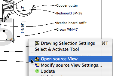
The classic case is when you're viewing a drawing and see a problem that must be fixed in the model. There's a great shortcut on the drawing elements' context menu, 'Open Source View', which takes you directly the viewpoint in question and sets the view options accordingly. If you have a pen set hooked to your view, you're looking at output pens in a model situation. You can change them manually or just squint while you fix the problem(s). This is output criteria interfering with model work and it's just wrong.

Summary: No pen sets in views. Output pens go with the drawing element.

There's no question AC has too many things in too many places. It's hard to remember where along the assembly line something gets bolted on. Is vectorial hatching a 3D window setting, a viewpoint setting, or a model view option? (Yes, yes, no.) Is a glitch in the output due to the model, the viewpoint, the view settings, or the drawing element?

It is a continuing frustration that the view settings don't include everything related to model display. But pens are different. Let the drawing element handle it. Tips:

• The drawing tool can have favorites. Set faves for drawings which need different pen sets.

• You should have a pen set column in the drawing manager.

(Heavily revised for AC10, though still a little clunky.) This is the standard workflow for issuing SK drawings.

More»

Grid Cell
Location: 1 General / Title & Layout

(Again, pardon the 'a'. Some things can't be fixed in place.)

This object represents the available area of a detail sheet grid cell, or group of cells. Use it in your details to plan how the detail will lie in the cell. Very similar to Sheet Area RND10, which is used for plans.

More»

There are the layer combinations for work and the layer combinations for output. In the past, the output LCs have had all their layers locked. The only reason for this was make clear to the user that they're not in a working combination. Not a critical point but there it is.

Now there's a stronger reason to have the layers unlocked in output LCs. In AC10, you can right-click on a drawing and choose 'Open source View' to, right, open the source view. (In AC/PM9, this command existed but it never worked as far as I could tell.)

Open Source View
If you are viewing a drawing and see something that needs fixing, you can open the view and get right to it. So the layer locking should get out of the way.

In the architectural LCs, all the visible layers are unlocked. In the specialized plans (electrical, e.g.), only the special layers are unlocked.

Guidelines for installing and updating AC10.

More»

Every drawing or set we give to someone else should be archived as a PDF in the project folder at 2 Output : PDF Archive. This is for convenience and our own protection.

More»

Append Date Icon
Another piece of the Publisher puzzle.

Publisher automates output processes, including file output. When Publisher saves files, it saves them to the path given in the Publisher set's properties. Under our AC10 workflow, this path should usually be 1 Projects/[ProjectName]/2 Output/Publisher Outbox.

When a publication is run, newly saved files will overwrite any that are already in that folder, without warning. One way to avoid this would be to change the path or the name of the output file before each publication. But this is too much work.

That's one issue. Another: There is no facility for autotext in Publisher output filenames. You can't create a filename with the date or project code, for example.

Append Date is an Automator application that tries to address these two issues. (I made it, it was easy.)

More»

« Newer | All Entries | 1 | 2 | 3 | 4 | 5 | 6 | 7 | 8 | 9 | 10 | Older »