On Land

Environment Information
At Rill Architects we run ArchiCAD on macOS. If you work at Rill, this is your stuff. If you don't, but you work in ArchiCAD, you may find something interesting. Anybody else, I don't know.
RSS
Standards Archive

« Newer | All Entries | 1 | 2 | 3 | 4 | 5 | 6 | 7 | 8 | 9 | 10 | Older »

L Wall2 and L Wall3 are for landscape walls.

L Wall2 shows in the floor plan, while L Wall3 does not. L Wall2 is hidden in the structure plans. We want to see landscape walls in the architectural plans for clarity, but we want to omit them from the framing plans if the aren't in the main contract/permit.

This layer sort of "forks off" from the layer S Slab.

Use it for framed structural decks (TJIs, 2x12s, etc). Continue to use S Slab for concrete slabs.

Why? Because decks aren't slabs. Yes, they're both made with the slab tool, but layers represent project elements, not tools. As much as possible, layer names should represent real things.

Where does this leave the layers A Deck2 and A Deck3? Right where they were. Model the deck surface on A Deck3. Model the structure of a deck on S Deck. Place 2D elements representing the (architectural) deck on A Deck2.

[Slightly updated, really just bumped. Originally posted in April 04.]

Turn the Schedule Symbol off and leave it off. At the bottom of the settings dialog you'll see a division called 'Dimension Marker'. Click the flyout at the top and select 'Door[or Window]TagJAM9'.

Why do it this way instead of the old way? Because the display of these markers is a display option. To show the markers, choose 'Show with Dimension' under the doors and windows display option. To hide them but show the swings, choose 'Show on Plan'. This allows you to show the swings in the electrical plan without the tags.

One glitch: For JAM8 windows, if the door/window is in a mirrored wall, the symbol will go to the wrong side. Mirror the wall segment again to fix it, or just drag the tag. The JAM9 windows won't have this problem.

This has been superseded by this.

More»

The modules for the assembly types (3 Resources / Modules / Assembly Types) and building parts (3 Resources / Modules / Building Parts-Existing (or) New) have been updated for AC9.

The layers have been updated and a couple objects modernized. And, thanks to Jon, the counter and cabinet depths are correct.

If you're not using the keyboard to switch tools, you're not living life to the fullest.

Chosen for convenience, the "main" tools:
` : Marquee
1 : Wall
2 : Slab
3 : Roof
4 : Column
5 : Beam
6 : Mesh

Note that these are in a row. The Arrow Tool is still the Right Arrow key. Esc will switch to the Arrow Tool if there's nothing else for it to do.

Chosen by initial:
W : Window
D : Door
O : Object
F : Fill
L : Line

Chosen for position:
E : Text
Opt+E : Zone

Chosen for appearance:
0 (zero) : Arc (Key has an arc and an ellipse!)
7 : Polyline ("&" resembles a polyline?)
8 : Spline
. (period) : Hotspot
[ : Section (get it?)
] : Detail (Goes with section.)
/ : Dimension

Arbitrary, but grouped nicely:
, (comma) : Radial Dimension
; : Level Dimension
\ : Angle Dimension

Modified initials:
Opt+L : Label
Opt+C : Camera

Other:
M : Lamp

Note: The only modifier key used is Option.

No key, tool rarely used:
Wall End, Corner-Window, Skylight, Stair, Figure.

More»

If I haven't made this clear, I would like everyone to move their 8.1 projects to Archicad 9 as soon as is convenient. The transition is virtually painless. Ask for help if you need it.

In honor of AC9, I renovated the project folder scheme. The old one had too many divisions at the top, and too many squirrelly folders, e.g., 'Reference'. I mean, what is that? I also thought it was wise to promote the layout book to the top level, which left the CDs folder somewhat bereft.

So here's the deal. Discussion is welcome.

More»

In PlotMaker 3 (and above), you can place special tags in text elements which can intelligently display information about the project, the layout, the drawings, and the system environment (e.g., the date). This functionality, and the tags themselves, are known as AutoText.

AutoText tags must be in all caps, and they must be inside greater than/less than brackets.

When viewed in Archicad, tags will always appear with their name. In PM, the tag is interpreted and the proper text is displayed.

The main categories of tags are:

• Info about the placed drawing,

• Info about the layout,

• Info about the system environment and the project files,
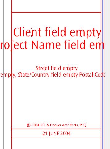
• Info about the project itself, as stored in the 'Book Info'.

We already use AutoText tags in our drawing titles. They appear as "DRAWINGTITLE" in Archicad, then display the proper drawing number, depending on the arrangement, in PM.

AutoText is also used to generate the sheet numbers in the layout book. In the place of the number on the master layout, we have the tag "LAYOUTNUMBER", which is interpreted in each layout according to each subset's settings.

The "LAYOUTNUMBER" is placed directly in the layout using the text tool. To see how it works, go to a master layout and activate the text tool. Click to start the text, then right-click and mouse over 'Insert AutoText...' The flyout contains all of the AutoText items. Select 'Layout Name', then close the text. Switch to a layout that uses that master, and you see the text has turned into the layout name. (In master layouts, layout- and drawing-specific tags will always be interpreted as 'Undefined [Something]').

The defaults for the following parameters the the main title block object have been changed to their respective AutoText tags:

• Project Name

• Type

• Street Address

• City

• State

• Zip

The SK title block uses AutoText tags in the Project Name and Type fields.

That means, new placements of the objects will have these values unless you change them. That means, you need to fill in the book info for the tags to be interpreted correctly (recommended), or edit the settings to display the info the old way. (But why?) Current projects should not be affected, but feel free to set up your book info and use the AutoTexts if you like. If you are going to issue SK sheets, this will make it much easier.

The templates have been updated with the new defaults. The 'Starting a Layout Book' workflow procedure now includes adding the book info.

For new projects, you must set up the book info, or you get this:


Wow, that makes 'Somebody Residence' look positively elegant.

SK sheets are the official format for issuing corrections, clarifications, changes, and other additional information after the construction set is issued. SKs become part of the construction documents, and should created and maintained with the same care as the big sheets.

Use an SK sheet whenever you have to issue document information between official revisions. Revision sets should be updated to include the SK information since the last issue. For geometry taken directly from the model, this will take care of itself via the traditional view updating process. Scanned drawings and other non-project-file info must be placed on an appropriate big sheet, in addition to the SK layout, so the next revision is complete.

We have developed a special title block for a letter size sheet, Title Block SK RND81. It enables you easily to create an SK sheet out of any geometry in the project.

The preferred method of putting out SKs is PlotMaker, using special layouts within the main CDs layout book. The layout book will automatically number the SKs as they are created, and keep them in one place for safety and organization. You can also import scanned drawings into the layouts, so that hand drawings can be maintained consistently with the rest of the documents.

It is possible to simply place a SK Title Block in Archicad, marquee the SK, and print the marquee area. While this method is quick, it does not create a permanent copy of the output, nor does it maintain your numbering. In addition, printing from Archicad does not have the same quality as printing from PM, since the colored pens have to be turned grey.

See also:
Title Block SK RND81
Getting the SK Layout Tools into Current Projects

M Fixt
Non-ceiling mechanical fixtures, such as floor registers. Shows in mechanical plan, or in the floor plan if you don't have a mechanical plan and you want to show the registers. (We did this on Stevens.)

M Fixt Clg2
Ceiling mechanical fixtures, such as ceiling registers or returns. Shows in mechanical plan and reflected ceiling plan.

M Equip
Mechanical equipment, such as furnaces, air handlers, water heaters. Shows in mechanical plan, electrical plan, floor plan, and section. If you don't want a particular element to show in section, turn the 3D off in the object.

« Newer | All Entries | 1 | 2 | 3 | 4 | 5 | 6 | 7 | 8 | 9 | 10 | Older »