Updated for Archicad 25.

All the common layouts (that we can think of) are blocked up in the project templates. These guidelines apply no matter when a layout is first needed.
Alphabetical by name of thing. Please suggest improvements and additions. Many things have changed, many have stayed the same. Layer theory hasn't changed much. Current as of Archicad 20, which prompted some layer changes.
Big table below the fold.
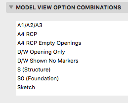
Beginning with Archicad 20, the fills division of Model View Options is obsolete and fills are handled by Graphic Overrides. This enables us to eliminate several combinations that were needed in Archicad 19.
Updated for Archicad 19.
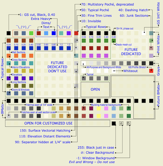
Pen sets let you change the appearance of output at the very last moment - when the drawing, based on the view, is headed out the door. The colors you see while working on the model can be completely different from the published output, and they should be.
Standard pens updated for Archicad 19.
The only substantive change since 2007 is that we've dropped pen 170 for structural posts on the story below. This was an ugly hack that's no longer needed since we can use Library Globals to control display of those elements.
That's a very small change, but I wanted it to be clear that these standards are still current. I updated the graphic. I have strong opinions about pen -1.
Sloppy modeling leads to sloppy documentation. That wall that's supposed to be 7'-0" long, but you built it 7'-0 5/64", so it dimensions at 7'-0 1/8", and the published output looks ridiculous.
Sloppy modeling doesn't clean up right in plan, section, elevation. (It looks fine in OpenGL with contours off. Great.) That means extraneous lines that either mislead the viewer or have to manually managed by you. Not everything cleans up, but everything that can, should. And sloppy modeling does not.
Once you have sloppy elements placed, you will likely refer to them to place other elements, and the slop spreads like a virus.
Sloppy modeling is not easier. This is how you model precisely:
• Use direct entry of distances. This means: Start placement, type 'R' (Hello world: Archicad default is 'D'), enter the distance and strike return.
• To place elements a set distance from a known point, move the origin (Opt+Shift) and use direct entry of X and Y by typing 'X' and 'Y'.
• If you are placing something 'roughly', it's still better to pick a number. Start the wall, e.g., and when it's 'about right', look at the R field (Distance in Tracker) and mentally round off the ugly number there. Then type 'R', enter your rounded distance, and strike return.
• Place the model with a sensible relationship to the global origin. A centerline, a corner, etc. You can reset the user origin to the global origin and 'feel around' with the cursor to see which end of Mr. 7'-0 5/64" is the bad end.
• If you're trying to center something, just center it. Draw any linear element from side to side, find the midpoint, and put something there. I would use a Center Line object because it is distinctive. Lesser but acceptable solutions include hotspots and non-printing lines. (Graphisoft wants you to use the new permanent guide lines, but I'm not a fan.) Whatever the thing, consider locking it. You can also use snap guides in AC19+ to find midpoints, or the old snap points constraint on the Control Box.
• Use a Center Point object to mark the center of curves, to make sure concentric elements are truly concentric. Show on all stories as needed. Lock it.
• Our plan-scale dimension standard is set to 1/8" precision. We only want to see output dimensions of 1/4" precision. (Unless there is an angle involved.) When you expect to see 7'-0" and see 7'-0 1/8" instead, that is your warning that something is off. Track down the 5/64" and fix it.
If any of these things is harder than clicking kinda wherever, I'm not seeing it.
Precise modeling is essential to Archicad success.
In the old days, things were different. How different depends on how old the days are. It's hard to anticipate every issue you might encounter in an old project. The first question is, what do you need from the project? Do you need drawings, a detail, or are we actually resuming work on the project?
Leads and pending projects should be placed in 1 Projects / zPending.
These are projects which have no modeling or design data with them. They might be just a proposal.
When a pending project actually begins, create the project folder as normal. Drag any documents in the pending folder to the new project folder. The proposal belongs in '3 Contract & Correspondence / Proposal'. Trash the project's 'pending' folder.
If a project does not go forward, we will move it to 5 Past Projects as part of our quarterly project cleanup.
When dimensioning, strive for stunning, perfect, complete, beautiful clarity. I'm serious.
This is everything I can think of about libraries management. There have been a lot of changes over the years.
Current naming standards. Still very boring.
These rules aren't set in stone, but if we all stay near the rules we all stay near each other. Like all standards, they work most of the time. When a situation is addressed by the standards, you can save your creativity for the projects.

BIM Server Libraries. Copies of our standard libraries for use in Teamwork projects.
Library Container Files. An LCF is a compressed archive of a library. It loads very fast and can't be messed up, so it's good for taking projects on the road assuming you don't need to modify standard parts. I try to update the LCF of our current versions' library (13 and 16 at the moment) on a weekly basis. But I might forget, and I certainly modify objects throughout the week, so if you need the LCF you should make sure it's up to date.
Master LIB [n]. Where n is between 7 and 20. The Master folder contains the current "1 Rill LIB[n]" folder, which is standard library that must be loaded for all current projects. It also contains a "Development" folder, which should generally not be loaded; things in there are either broken, unfinished, or otherwise unworthy.
When we start using a new version of Archicad, I copy the entire Master LIB folder and give it the new number. When you switch a project to a new version, you should also change to the newer Master LIB. It will be virtually identical to begin with, but over time the old versions will fall behind. I generally only treat the newest Master LIB as "live" for the purposes of new development and bug-fixing. Back-saving objects, unlike PLN files, is nearly prohibitive in its awkwardness.
Other LIBs. Just what it says. Old project libraries from the pre-embedded days. Old Archicad libraries. (I've lost the 5.1, but we still have the 6.0.) Extracted versions of recent/current Archicad libraries. (Archicad libraries are LCF files. If you want to search them using the Finder, they need to be extracted.)
Alphabetical by name of thing. Please suggest improvements and additions. Many things have changed, many have stayed the same. Layer theory hasn't changed much. Current as of 16, and I'm not anticipating big differences in 17.
Big table below the fold.
• Wall Cleanup.
Plan layer combinations should have different intersection codes for plan and 3D walls. (E.g., A Wall Ext has '1', A Wall3 has '2'.) This eliminates gaps where visible and invisible walls meet.
Wall cleanup has improved greatly over the years, but can still be tricky for complex intersections. Use a patch if you must.
• Display Order.
(Front, back, etc.) Use display order to to make overlapping elements stack correctly. In order for elements to mask elements behind them, they need a fill with a background pen. If you don't want a fill pattern, use 'Empty Fill'.
Generally, annotations should be all the way in front so they aren't obscured by anything. Walls should in front of everything except annotations. Beyond that, you have to pay attention. Counters in front of floor fills, soffit lines in front of counters, stair railings in front of treads, etc.
• Pens.
More on pens here. Walls are 5-weight (usually 15). Edges (Counters, stairs) are 2-weight. Dashed overhead elements are 2-weight. Appliances, plumbing fixtures, and other such objects are 2-weight. Floor finishes are 150. The background pen of construction elements is 50, and existing construction elements are overridden by pen 91.
A note on composites: Contour, separator, and background pens should set correctly in the composites. Walls in plan should be set to use the composites' pens. Stud wall composites should have the separator lines hidden; that is a composite setting, not a wall setting.
• Floor Finishes. Either: 1) Fills on F Floor Fin2. 2) Slabs with a cover fill on F Floor Fin2. 3) Cover fills on the zones. In practice #1 is most common.
• Dimensions. Here. For small rooms, consider enlarged plans and put the dimensions there.
Roundup of issues with daily shutdown, data backup, and power failures.
In Archicad terminology, a marker is a special object that has a subordinate relationship to another element, representing the element and/or saying something about it. Viewpoint markers represent viewpoints in project windows. Each viewpoint type has its own marker objects. There are default markers for each one in the Archicad library, but we (as usual) use customized stuff. Each marker is dedicated to a viewpoint, but all the markers have a lot of parameters in common. Here I will lay out those similarities, as well as the special features of each marker, while making sure we're clear on the correct marker for each viewpoint type.
Executive summary: A new layer for elements in layouts and in the title block worksheets. There should be no elements on the Archicad layer.

• The title block object and other stuff in its detail/worksheet window
• Drawing elements on layouts starting in AC10
• Master layout drawings and annotation elements
And it's never given us any trouble, but.
The concrete reason to forswear use of the Archicad layer is that it interferes with Teamwork. The only way to have the Archicad layer in your workspace is to have 'exclusive access' to the project, which is inconvenient in a real shared workflow. It's true that we don't use Teamwork much, but you never know.
Rather than confront the question under deadline pressure some time in the future, I'm changing the standards and templates now to include a layer for 'Layout' elements. This layer, +Z Layout, holds any element placed directly on a layout, including drawing elements, texts, PDFs, etc. It is also the layer for the title block object and anything else within the title block worksheets. The layer is visible and unlocked in all layer combinations except 0 Working Model.
Once all that always-showing stuff is placed on a regular layer that could potentially be hidden, you might wonder how to make sure it always shows anyway. The layout environment actually has its own layer settings, which are maintained simultaneously with the model window layers. Changing the layer settings of one does not affect the other, thank goodness. The templates are set up with the +Z Layout visible in the layouts. As long as you leave it alone, it will always show. If you do hide it, probably by accident, and WOW you'll know right away when everything vanishes, turn it back on. Layout layers are unaffected by view changes. This should be a set-it-forget-it situation.
Some people use multiple layers to turn layout elements on and off, but I don't see the advantage of that for us at the moment. One concern would be that layout layers can't be saved, with views or otherwise, so the user must remember to manage the layers before publication. I would be inclined to handle such visibility control in the title block worksheets. Here is some AC-Talk discussion.
The other advantage of using this standard is that the Archicad layer rule is much simpler: Don't use it, full stop.
Template changes:
• New layer +Z Layout. Show in all combos except Working Model.
• All title block worksheet elements to the new layer. Use F&S for all elements on AC layer, then Edit Selection Set to change.
• Set layer environment layers to combo xxAll, which shows everything.
• All master layout elements to the new layer. On each master, use F&S and ESS as above.
• All drawing elements on regular layout to the new layer. In Drawing Manager, sort by Placed To, highlight all non-master drawings, change layer in settings.
• Change default layer of Drawing tool.
• Redefine Drawing tool favorites with the new layer.
• Save favorites.
The MVO dialog has three divisions. Options for Construction Elements concerns the display of real things, including openings, columns, beams, and markers. Options for Fills and Zones concerns how different categories of fills are displayed; turning cover fills on and off, e.g. Options for GDL Objects has only one item at the moment, the beloved Story Viewpoint Type, also known as the ceiling switch.
The keyboard shortcut to open the dialog is Cmd+9. I think the MVO dialog is pretty good about previewing the effects of most of the controls.
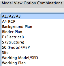
Rather than describe each combination, or heaven forbid build a table, I'll describe the A1/A2/A3 combination, then how the others differ.
What Shows
Note, November 10, 2017: Anywhere you see the layer +C Site Annotation, you can use the layer +C Site Note if the current project doesn't have the annotation layer. (This layer is quite new as of this update.) The difference is not important unless the site is being shared among multiple projects. If the site is shared, the annotations layer is for permanent data about the site, such as north direction, survey dims, and topo labels. Notes specific to the project go on +C Site Note.
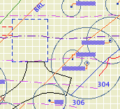
• General. The site plan is generated from the First Floor story. The 3D grade mesh is not shown because its pen and linetype options are too limited.
• Property boundary with metes and bounds. For the boundary, use an empty fill. (Only a fill can report its area, and you'll need the property area for the project information.) If north is set correctly and the boundary is precisely drawn, you can use and object for the metes and bounds, Survey Dim RND9, located in Graphic Symbols. Layers: C Site2 for the boundary, and +C Site Annotation for the text.
• North arrow object. North Arrow JAM9, located in Graphic Symbols. If north is set correctly, you can turn on the 'Use Project North' parameter. Layer: +C Site Annotation
• Setbacks. Layer: C Site2 Use lines, arcs, or polylines. Setbacks should be labeled 'BRL' (building restriction line). Special restrictions can be labeled more specifically; 'Conservation Easement', for example. Layers: C Site2 for the lines, and +C Site Annotation for the text.
• Topographic survey contours. If available. Use splines. Don't use lines, polylines or arcs. If you have lots of little segments, the dashed lines will never look right. Typically, we will get contours at two-foot intervals. The sea-level elevation of each contour should be called out, unless the contours are very closely spaced. In these cases, labeling only the ten-foot contours is OK. Layers: C Topo Existing and New for the splines, and +C Site Annotation for the text.
For boundary, setback, and topo text blocks, pay attention to the anchor point. This will help the blocks stay in position if you do multiple site plans at different scales.
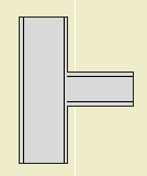
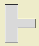
• Building footprint. Layer: +C Footprint.N The footprint is the outline of the building as it meets grade. You will probably use the basement plan to get it. With the Site Plan layer combination active, show the A Wall Ext and S Wall2 layers. Trace the wall outlines with a polyline. You can show the basement story as trace (FKA ghost), or draw the polyline on the basement story and cut/paste it to the first floor.
Show dimensions from the footprint to the property boundary at key locations. For an addition project, the addition portion of the footprint should be filled with a diagonal pattern.
• Trees. If available. Use the object Tree JM10, located in 02 Site / Trees. Don't show removed trees unless you need to. Layers: L Tree2 or L Tree A. Trees on the 'A' layer will also show in the architectural plan. If you have modeled trees, you can place them on these layers or use L Tree3 to hide them in plans.
• Top view of building. This can be a roof plan or a 3D top view. This is a separate drawing overlaid on the site plan drawing.
• Additional building-related 2D elements. Anything you can't get to cooperate with the top view drawing can be drawn separately. Layer: +C House Line.
• Driveway. The layer L Drive2 shows in the site plan layer combinations. If you find that showing this driveway conflicts with the site plan somehow, you can modify the layer combination to hide it, and then redraw it with lines, arcs, and polylines on the C Site2 layer.
• Street. Layer: +C Site2 Use lines, arcs, or polylines.
• Notes. Label the major site and project elements. These are, at least, the existing house and addition, the driveway, pools, large terraces, septic fields. Layer: +C Site Note.
Line Types
• Boundary: Property Dot-dash
• Setbacks: BRL long dash
• 2' contour: Dense dashed
• 10' contour: Long Dashed
• Driveway and street: Solid
• Footprint: Dense Dashed
Fonts
The usual, but to review: Lucida Sans for notes. Tahoma for dimensions including boundary data. The street name looks nice with a serif font; use Times.
Now we have some standard details, in the form of module files, which you can drop into whatever projects might appreciate them. They are located at 3 Resources / AC / External References / Standard Details. These are distinct from the Assembly Type details, which specify the components of walls, roofs, slabs, etc.
I will define a standard detail as a building condition always done in a certain way, independent of superficial architectural characteristics. For example, a brick window header will always be flashed with the same technique, regardless of the size or color of brick, the joint finish, or the shape of the brickmould. Those architectural specifications would be noted in other details and/or in the specs. Further, standard details represent CYA-type technical matters that we want to be sure not to forget, so the easier to drop them in the better.
The first wave of these details concerns the heads, jambs, and sills of openings (doors and windows) in walls finished with wood siding, stone, and brick.
How to use them
Create an independent detail window. Give it a descriptive name such as 'Typ Brick Window Head'. I like to use the ID field to keep the standard details separate from the 'real' details, so I would use an ID like 'Standard01'.
You can either merge or hotlink the desired module into this new detail window. Merge is essentially a paste operation, and the drawing elements will simply appear in the window and act normally.
Hotlinking maintains a live connection to the module file. If the module ever changes, you would get a notice to update it upon opening the file. Elements of hotlinked modules cannot be edited; the whole thing will act like a big locked group. (Module elements' nodes are square donuts instead of round.)
Which way is right. I will say merge in this case. As a 'Standard' detail, it shouldn't change often, and having fewer external references simplifies taking the project off-network.
Create a view of the detail window and drop it on a detail layout. Rinse and repeat.
More info
Don't be distracted by the Standard Details.PLN file in that External References folder. The project file is the administrative resource for generating the module files. Here is a summary of my detail method as it relates to the assembly types. Here is the really sick module generation method, which has nothing to do with the end user. 'Sick' can mean 'gross' or 'cool'.
Please let me know immediately if you encounter a module with multiple stories. How will you know? Such a module will not merge into a detail (or any non-plan) window, and you will get a warning to that effect. If you try the sensible workaround of merging the module into the plan window and then moving it, you will eventually notice multiple empty stories added to your project.
Both of these outcomes are sick in the uncool way.
This problem started in AC11, when it became possible to save multi-story modules. (Previously, if you wanted a three-story module, you needed three one-story modules.) This feature has a crippling bug that was reported in early beta, yet remains unfixed. When you publish a module from a multi-story project, you have a choice of what stories to publish: All, Current, or a range. It doesn't work. When you attempt to publish a single-story module, you get a module with all the stories of the parent project, with the content of only one story, the one that was 'current'.
So, after cool-sick publishing the modules, I have to gross-sick open each one of them and delete the extra stories. Of course, some day I will tune up a detail and re-publish it and then forget to fix it, and you will be sad when you try to merge it, and then you will tell me.
I would like to take this opportunity to express my great displeasure with Graphisoft's current quality assurance standards. This is a major bug in a medium-size new feature. They have known about it for months. They have released four patches to the shipping version on top of a number of beta versions. This bug impairs the ability of serious firms to use Archicad at a high level. It wastes your time and mine. It adds to the apprehension about future releases and how long they, in turn, will take to stop messing up our workflows, if ever. Archicad 10 still has what I consider show-stopping bugs, but it will never be patched again.
It is infuriating today and worrisome for the future.
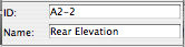
Every viewpoint has a name and an ID. The name is important and is often used for output. The ID is never used for output, but wherever possible we use the ID to help organize the project map and view map.
The behavior of IDs varies among the viewpoint types, so here's a cheat sheet.
The primary Schedules have an ID to sort them to the top of the menus. Incidental schedules don't need IDs. This may change.
Cameras and paths have unique IDs that can't be changed.
Summary: Viewpoint IDs are not used for output, so use them to help sort the lists. Names are used for output: Use the name you want to see on the paper.
The IDs that do matter for output are those of the layout book items; subsets, layouts, and drawings.
Drawing IDs are usually generated by the layout, either by the grid or the order of drawings in the layout book tree.
Layout IDs are usually generated by the subset.
Subset IDs are set by the user, and the subset ID becomes part of the layout ID.
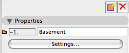
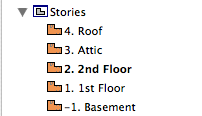
Views also have IDs, but they should typically inherit the viewpoints' IDs, so the lists will appear the same to us. All view IDs can be customized or set to 'None', but you can usually just leave them be. In the templates, I have deleted all the IDs for story (plan) views, because stuff like "-1. Basement" looks idiotic.
Standard pens updated for AC11.
Changing the pens is a pain, and it's potentially disruptive. I try to avoid it. With this update, I'm trying to minimize disruption while building a system that can adapt in the future. It should hold us for a while.
Template View Map orientation session.
Remember that views are viewpoints (stories, sections, details, etc) plus user options such as scale, layers, model view options, and dimension standards. Views become drawings in layouts.
We need views for each kind of output we're going to produce. Additionally, we want views for the various modes of work we do in the model.
We do the same kinds of output over and over, and the same kinds of model work. When you're doing the same things all the time, the templates should support you by getting a lot of it started.
These are the top-level subsets of the template view map:
• Working: Views which use the 'Working' Layer combinations. Use these views for day to day work on the project.
• Schematics: Intended for output in the schematic design phase. These views default to 1/8" scale.
• CDs: Intended for output in the Construction Documents and Design Development phases. The plan, section, and elevation views default to 1/4" scale. All other output subsets are included; interiors, structural, RCP, etc.
• Schedules: Views of schedule viewpoints for windows, doors, finishes, etc.
• 3D Views: Perspective, axonometric, top views from the 3D window.
• Note & Title: Title blocks, drawing list, vicinity map, project information, other annotation-type drawings.
• Background Plans: Stripped-down plans for DWG export if anyone asks.
• Binder: Small-scale plans and elevations for the post project binder.
Within the Working, Schematics, and CDs subsets, there are cloned subsets relating to the various viewpoint types, including at least:
• Plans
• Sections and elevations
• Wall sections
• Details
• Reflected ceiling plans
• Interior elevations and enlarged plans
• Electrical plans
• Structure plans
The Schematics and CDs divisions are named after the sheet they are published on: A1 Plans, A2 Elevations, and so on. Note the symmetry with the Schematics and CDs subsets in the layout book.
The divisions within the Working subset correspond to these output divisions: Working Plan, Working Elevation, on like that. (Working Model gives the whole model with no annotations.)
The working subsets are for us, and the others are for the documents.
I hope this illuminates the view map structure in our templates.
This will go live when we move to Archicad 11. It doesn't have anything to do with 11 per se, but it's easier to make organizational changes at a version break.
On 3 Resources / AC, we have a new folder called External References. This will hold all the external drawing and annotation resources which are used in the templates. These are:
• The Abbreviations PDF on the cover sheet.
• The Drawing Symbols PLN. This generates the views that wind up as the symbol keys on the cover sheet.
• The General Notes PDF for the T2 or T3 sheet.
• Standard assembly detail modules, which are hotlinked into detail windows.
• Electrical Plan symbols.
• Probably other things.
This is all the standard stuff. If a project has external references particular to itself, those go in the project folder.
In the current system, if you can call it that, we have these resources in at least three places and it's a hassle if you need to relink something. In the 11 template it's clearer.
The standard project folder setup. The screenshots are out of date, but the descriptions are current as of Archicad 21.
Summary: With the model and the layouts in one file, pen sets manage the difference between the model pens and the output pens. In addition, they can do view-option-type tricks.
Background: In Archicad 9, there was one set of pens. In PlotMaker 9, there was also only one, and it could be different from the set in AC. Or, each drawing could have its own pens, but it was impractical.
Our standard has always been to use a colorful set of pens for modeling, which translates into a black/white/gray set of pens in layouts. We are far from unique in this arrangement.
In 10, they threw PM into the abyss, so they needed a method to maintain at least those two groups of pens within the new unified project file. So, Pen Sets.
Note: This post has been updated for AC18.
Current naming standards. Still very boring.
These rules aren't set in stone, but if we all stay near the rules we all stay near each other. Like all standards, they work most of the time. When a situation is addressed by the standards, you can save your creativity for the projects.
The workflow: Build the model, fill it with information, decide what you want to show, and get the drawings out as automatically and predictably as you can.
We want to focus on the model; that's where the building is. We want the output to just work. Modeling and annotation is craft. Output is for robots.
This duality is evident in pen handling. We have a lot of pen sets, but it boils down to working and output.
Output pens have to look right when the work is done. Their settings are driven by graphical criteria, much of which predate any use of computers. Working pens are there to help the user interact with the project.
These two purposes have nothing to do with each other, and in our standards the two types of sets are radically different in appearance: Mostly black for output, and as many colors as we can find for working. I'm not going to work in black and I'm not going to print in color.
In moving between model work and layout work, the pens need to cooperate. Hooking pens to views breaks the flow.
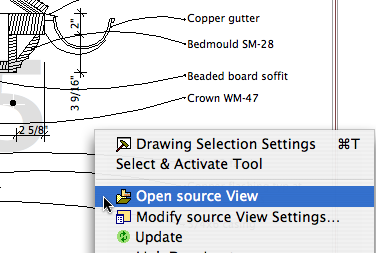
The classic case is when you're viewing a drawing and see a problem that must be fixed in the model. There's a great shortcut on the drawing elements' context menu, 'Open Source View', which takes you directly the viewpoint in question and sets the view options accordingly. If you have a pen set hooked to your view, you're looking at output pens in a model situation. You can change them manually or just squint while you fix the problem(s). This is output criteria interfering with model work and it's just wrong.
Summary: No pen sets in views. Output pens go with the drawing element.
There's no question AC has too many things in too many places. It's hard to remember where along the assembly line something gets bolted on. Is vectorial hatching a 3D window setting, a viewpoint setting, or a model view option? (Yes, yes, no.) Is a glitch in the output due to the model, the viewpoint, the view settings, or the drawing element?
It is a continuing frustration that the view settings don't include everything related to model display. But pens are different. Let the drawing element handle it. Tips:
• The drawing tool can have favorites. Set faves for drawings which need different pen sets.
• You should have a pen set column in the drawing manager.
(Heavily revised for AC10, though still a little clunky.) This is the standard workflow for issuing SK drawings.
(Again, pardon the 'a'. Some things can't be fixed in place.)
This object represents the available area of a detail sheet grid cell, or group of cells. Use it in your details to plan how the detail will lie in the cell. Very similar to Sheet Area RND10, which is used for plans.
There are the layer combinations for work and the layer combinations for output. In the past, the output LCs have had all their layers locked. The only reason for this was make clear to the user that they're not in a working combination. Not a critical point but there it is.
Now there's a stronger reason to have the layers unlocked in output LCs. In AC10, you can right-click on a drawing and choose 'Open source View' to, right, open the source view. (In AC/PM9, this command existed but it never worked as far as I could tell.)
In the architectural LCs, all the visible layers are unlocked. In the specialized plans (electrical, e.g.), only the special layers are unlocked.
Guidelines for installing and updating AC10.
Every drawing or set we give to someone else should be archived as a PDF in the project folder at 2 Output : PDF Archive. This is for convenience and our own protection.

Publisher automates output processes, including file output. When Publisher saves files, it saves them to the path given in the Publisher set's properties. Under our AC10 workflow, this path should usually be 1 Projects/[ProjectName]/2 Output/Publisher Outbox.
When a publication is run, newly saved files will overwrite any that are already in that folder, without warning. One way to avoid this would be to change the path or the name of the output file before each publication. But this is too much work.
That's one issue. Another: There is no facility for autotext in Publisher output filenames. You can't create a filename with the date or project code, for example.
Append Date is an Automator application that tries to address these two issues. (I made it, it was easy.)
I've taken another stab at standardizing the Work Environment. This for AC10 only.
The integrated layout book in AC10 makes it even easier to start layouts in advance, in the templates, and have them nearly 'just work'. All the common layouts (that I can think of) are blocked up in the project templates. Developing the layouts consists mostly of framing the plan, tuning up the section/elevations, and arranging the drawings on the sheets.
I inherited a project where an important dimension was supposed to be 12'-9" and instead it was established as 12'-9 9/64". The fraction rounds to 1/8", which resolves in the dimensions (12'-9 1/8"), so I have to fix it or customize the dim text, which would violate various Prime Directives.
And it's my fault I didn't catch it before adding all the pretty bits, which now have to be dragged and stretched by 9/64". But the point is that a project shouldn't leave schematics which such imprecisions.
It's just as easy easier to build precisely: Start, shift or guideline, 'R', value, done.
It doesn't mean you can't be sketchy in AC. Just rationalize the measurements before/as you go to DD. Even if you're not doing the CDs, be considerate of your colleagues and tighten up the model before it gets crazy-complex.
It is much more comfortable to work in a model that is precisely done. The mind becomes accustomed to seeing the nice round fractions, so when there is an ugly number, it gets your attention.
Eighths in dimensions at 1/4" scale make us look silly to the builder, except in rare circumstances. Unless you're talking about a funny angle, 1/8" has no effect on the design, and it will be ignored, unless chuckled at.
And no, you can't change the dimension standard to 1/4", because if your model is sloppy, the sloppiness will manifest as rounding errors rather than random eighths.
If the model is precise, the dims will take care of themselves, and you will have more time for other things.
So please model precisely, from the beginning. Banish all but the specialest eighths, and most of the quarters. Halves are OK... big and almost round.
One more thing. When you have 9/64" in a measurement, it's your fault. AC does not make these mistakes by itself, at least not as near the origin as we work. No mystery, just fix it and move on to something more interesting.
1. Duplicate the zTemplate 10 folder and rename it with the project name. To duplicate a folder, drag and drop it within the same window while holding down the Option key. Name the folder after the client. If this is a second, or later, project, add a number. (Please don't use roman numerals, they are hard to read.) If it's a sub-project or related project, add a descriptive term. Examples: Stevens. Kernan3. Salamander Garage.
2. Within the fresh project folder, open the project file template for new home or addition. The template names end in .tpl. The new template, 'NewHome10.tpl', is at the top of the project folder. The existing conditions template, 'Addition10.tpl', is in the '4 Site & Existing Conditions' folder.
3. In the library manager, make sure you have the following libraries loaded:
• From your local Applications / Graphisoft / Archicad 10 folder, 'Archicad Library 10'. (Note: Load this whole folder. This is different from AC9, where we would load only the 'Archicad 9 Library.pla'.)
• From the carrot (2 Resources), '1 Rill & Decker LIB10'. Don't load the entire '2 Project LIB10' folder. Click 'OK' and 'Done'. (Much more on libraries here and here.)
4. Once the libraries load, Save As. Format: Archicad Project File. For the name use the client name, similar to the folder name. If the folder is named 'Box Elder', the project should be 'Box Elder.PLN'. For an existing house use 'Existing Box Elder.PLN'.
5. Go to the Finder and delete the project templates from your project folder. They are no longer needed. If by some weird chance you need a template again, you can always get it from the zTemplate folder.
6. Back in the project, fill in the Project Info (File -> Info -> Project Info). The relevant fields are Client, Project Name (Residence, Addition, Renovation), Street, City, State/Country (State), Postal Code (Zip).
7. Set up the stories. Story elevations are floor-to-floor. Important: In AC10, we no longer set the roof story to the height of the top occupied story (Attic, 2nd floor, etc.). In order to interact properly with the Floor Plan Cut Plane, the roof story should be set well above, perhaps even higher than you think. (12'?)
The templates contain an attic story by default. If your project doesn't have an attic, delete this story. You should also delete the attic-related layouts.
8. Build the model until it's done or someone tells you to stop.
Once the model is to-a-point, it's time to prepare the layouts for the model and vice versa.
In the templates for 10, I've modified the layer combinations as suggested here. There's a couple of tweaks since then.
Changing the LCs is a minor change compared to changing the layers themselves, which can be very perilous. (There are a couple of layer changes in the new templates. Just a little peril!)
In this theory of layer combinations, there are three main types, and then a couple oddballs. The three:
• Output. Used by publication views.
• Working. Where you spend most of your time.
• Special Tasks. Unusual LCs for doing a certain task once in a while. E.g., Site cutting, building stretching, elevations with just notes.
The new LC arrangement makes these categories clearer. The working LCs begin with numbers. The output LCs begin with the letter of their sheets. The specials begin with x. The oddballs: The binder LCs begin with z. Since they're not used until the very end, they have to be last. 'zzz All' is sort of administrative, and you never use it in real life.
I've tried to make the purpose of each LC self-evident in the name.
Here's the list. (Existing/addition-only LCs are indicated by '*'.)
- ! Ex1 Existing Plan*
- ! Ex2 Existing Elev*
- ! Working Existing Model*
- ! Working Existing Plan*
- 0 Working Model
- 1 Working Floor+Roof Plan
- 2 Working Elev+Sect+Detail
- 3 Working Wall Section
- 4 Working RCP
- 5 Working Interiors
- 6 Working Site 120
- 6 Working Site 240
- A1 Floor+Roof Plan
- A2/3 Elev+Sect+Detail
- A3 Wall Section
- A4 RCP
- A5 Interior Elevs
- A5 Enlarged Plan
- C1 Site Plan 120
- C1 Site Plan 240
- D1 Demo Plan*
- E1 Elec Plan
- F1 Furniture Plan
- M1 Mechanical Plan
- P1 Plumbing Plan
- S0 Foundation Plan
- S1 Structure Plan
- S2 Structure Model
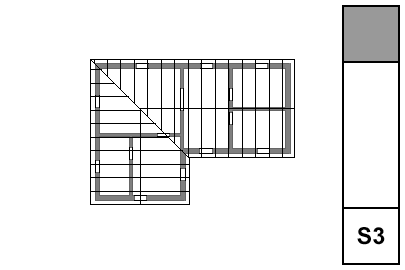
- S3 Structure Wall Mask
- View 3D
- View LW Render
- x Background Plan
- x Elevation Notes
- x Gross Area
- x Object Lab
- x Shoot RCP
- x Shoot Roof Plan
- x Site Cutting
- x Stretch House
- x View Chimney
- x View Flues
- x Working Dims Plan
- x Working Trim
- x Zones
- z Binder Elevation
- z Binder Plan
- z Existing Binder Elevation*
- z Existing Binder Plan*
- zzz All
Standard pens updated for AC10.
Changes:
• Pen #1 is not a good choice for a cut pen. Use 15,25,35,...
• There's a new typical row: The 160s. They're blue-gray. I recommend them for use with doors and windows. Use the 20s for stair elements.
• Pens 191-196 are the 'white-out' pens. They can be used to mask unwanted lines in section windows. More below.
• Colors are still used to categorize section markers, but the pens now come from the typical rows. Yawn. This shouldn't even be noticeable.
Alphabetical by name of thing. Please suggest improvements and additions. Note: I change the date whenever I update this, so it will pop up every now and then. Rest assured it's not all new. Big changes will have a post of their own.
Updated for 10. You will see these changes in the templates when you start a project in 10. I figured now is the time to make changes. Nothing too major:
• +Z SK Title is gone. SK titles should be placed in the layout only.
• Most +L layers become +C instead. C=Civil and is more standard.
• +L House Outline becomes +C Footprint.
• Z Light is new, for sun and sky objects for LightWorks rendering.
• We're going to use real section markers:
+Z SE & Detail Object becomes +Z SE Print. Use this layer for sections that print.
+Z S/E Tool becomes +Z SE Hide. Use this layer for junk sections and others you don't want to see in plan. (At the beginning of the project, all the markers are on the hidden layer. Move them to the Print layer as needed.)
• +A Roof Plan Line is gone. Use A Roof2.
After some experimentation, this is the best method I can find for using external, standard details. It definitely has room for improvement. The biggest improvement would be for AC to allow detail markers to reference external drawings. It's a huge hole in the program that has to be fixed. In the meantime this isn't too bad.
The executive summary: Copy details from projects and clean up their layers and other attributes. Place the details in a central PLN file, one per story. Or, draw them from scratch in the central PLN. Publish modules of the details. Hotlink or merge the modules into detail windows of running projects, and use detail markers to refer to them normally.
In this example I'm talking about the wall and other assembly types. It could used for any standard details you would like to share. Also, we will use this as a standard method beginning with AC10. In the meantime, everything here which concerns placing detail modules can be applied to current assembly modules at 3 Resources / Modules / Assembly Types.
The current standard for library loading is to load only the folder specific to the project. That is, don't load the entire 2 Project LIB 9 folder. I updated the templates so that the only libraries loaded by default are 1 Rill & Decker LIB 9 and AC9 Library Special Edition.
When the time comes that you need project specific objects, create a folder in 2 Project LIB 9 with a name like Projectname LIB.
When the project is completed and moved to Past Projects, the project library should be moved to 2 Libraries / Other LIBs / Past Project LIBs.
If you know of an object in a project library that you could use, ask the person who made it to move it into the standard library. Or, remember that you can load objects individually.
The idea is to not load objects that you will never use, such as other people's patches.
This is the definitive statement on loading libraries. I'm putting it in the Standards panel of the sidebar. Like the other standards things, it will probably be updated occasionally.
Update: From the Project Libraries, only load the folder for the current project.
It would nice to have standard details in one place, where any project could use them with no need to redraw anything. These would be standard assembly types, foundations, flashing, etc.
You can place views from any number of external project in a layout book in 9 or 10. The trouble comes in when you want to refer to the external drawing with a detail marker. Even in 10, this is still not possible.
So we have to consider a couple imperfect alternatives.
• Maintain modules, one for each detail. Merge or hotlink the modules into detail windows within the project. Refer to the internal detail drawings normally.
If you hotlink the modules, they can be truly standardized, with any changes distributed to all projects by updating hotlinks. The drawback is the module reference warning if you take the project off network. No harm, just hassle. (You could choose to break the hotlink, which would leave the detail intact, but it wouldn't be connected to the original.)
As an alternate to separate modules, you could place all the details in one project file, with one detail on each story. In this case, merging is not an option. You would hotlink the stories and optionally break the hotlinks.
Then you could use Publisher to create modules if you wanted them.
The one-project method also makes attribute management easier. It's important to rigorously control attributes so you don't 'contaminate' the current project.
Using hotlinks to the detail project stories presents a problem: You can't insert a story without breaking the links in projects. Ouch.
• Use external views directly, even though the referencing doesn't work. You would need a fixed ID, specific to the detail, which would appear in a drawing title object in the detail, and in the detail ID in the project. These IDs would bear no relationship to the sheet. Weird.
Conclusion:
• Create the details in a project file, one on each story. This is simpler generally and helps with the attributes.
• From this project, publish modules of the details. Then the modules themselves are hotlinked or merged. The detail project becomes an administrative resource; users don't interact with it directly. The stories can be managed for the convenience of the 'detail administrator'. Whenever a detail is added or changed, republish the modules.
• Hotlink or merge the modules into project detail windows and reference them normally.
Details need to be processed before merging them into running projects, or into a details PLN. It is important to avoid merging unwanted attributes, especially layers. This process simplifies the layers and gets rid of all the unneeded attributes.
This method should be considered alongside A Method For Standard Details.
Standard details will be administered by one or two people at the most.
Hmm, lots of space left. We use beige because everything shows against it: White, black, gray, yellow. Then one day I noticed that our background is almost the same color as buff trace, and it's probably for the same reason. It's interesting how you can go through a completely different process and get the same conclusion as someone 100 years ago or whatever.
What else. In AC8 and before, each window had its own background color. Now there's only one, but the grid color is unique to each window. I'd like to have one detail window with a white background for making object previews.
I'm happy to announce, and I hope I don't regret it, that we can email PDFs to MBC. And they will print them, and the drawings will probably be alright. I'm sure there will be some tuning up to do, but I think we have it working.
This is the address. Put the job details (copies etc) in the message. The file size limit is 50MB.
Let me know if you have any problems.
I found this 90% finished in the Ice folder, so I wrapped it up. The main difference is that the text expansion is now handled as a real number, consistent with the expansion feature of text in AC. The default expansion factor is 2.0.
Also: All the drawing names default to Title Case instead of ALL CAPS. Listen, all caps is played. It's a holdover from the hand-lettering days, which I barely remember. Nobody else in any print, design, or writing field uses caps all the time just because. It is hard to read. It looks like shouting.
Played.
Also, in the future (I'm optimistic), we will use automatic drawing titles. (Yes, they can be automatic in 9, but they're not parametric, and they don't cut it.) The name of the SE marker will be the name of the drawing. I'm not going to look at a Navigator full of CAPS all day.
Bury all caps, not praise.
To facilitate the creation of post-project binders.
Actually, we have been phasing it out for a while. Long ago, it was the default section cut pen for Walls Int and Ext, but that was changed to 15. The same goes for the section cut pen for structural slabs and decks.
So I envision this having very little impact, but I'm giving plenty of warning anyway. I don't know how long exactly. Put it this way, in AC10 it will be official.
Why. We have used pen #1 as a section cut pen, which means it's heavy. Pen #1 turns up as the default pen in a lot of circumstances in AC, and its weight in our setup is not a good default weight in most cases. Therefore, I want to change the weight of pen #1 to something along the lines of pen #12. If you end up with pen #1 by accident, it won't be obnoxiously heavy. But if I change the weight, I need to be sure no one is using it for a section cut pen, or at least we're out of the habit.
So stop using pen #1 when you want a heavy line. Use 15, 25, 35, 45,... instead.
Competition submission materials should be kept in the project folder. This applies to current and past projects.
Under the current template folder scheme, create a folder in 2 Output called 'Competitions'. (The zTemplate folder, as of now, already has this.)
Under the old template folder scheme (01CDs, 02 Reference, etc), create a folder called 'Competitions' at the top level.
Within the Competitions folder, create a folder for each submission, giving the name of the competition. Example: 2 Output / Competitions / Remodeling 2006/.
All files pertaining to the submission should be in there: PLNs, layout books, images, PDFs, forms, etc.
You'll be glad you did!
Everything in the general framing plan discussion also applies to roof framing plans. There's a few special considerations:
• The roof framing plan should usually be generated from the top occupied story, not the roof story. For most projects, this is either the attic or the second floor. In the past, we have used the roof story, but not any more. It is very beneficial to show walls in the roof framing; in fact, we should show walls from multiple stories where applicable. By using an occupied story for the plan, it's one less story to be shown using the trick linked above.
• Show the outlines of the roofs. It is not feasible to show the roofs themselves, you must trace them or copy and paste from the 3D window in the classic style.
If you are showing the actual roofs in your architectural roof plan, put the traced/pasted roof lines on the +S Struct Note layer. If you are using the cut and paste method for the architectural roof plan, you can use the same lines for roof framing.
If you have dedicated structure roof lines (not reused in architectural), change the hips and valleys to a dashed linetype.
To put it another way.
Option 1 (preferred): Use roof elements on A Roof2 for the architectural roof plan. Use copied lines for the roof framing, on +S Struct Note. Switch the hip and valley lines to dashed.
Option 2: Use copied lines for the architectural roof plan, on +A Roof Plan Line. The same lines show in the roof framing. You can't do the dashed line thing.
• If hip and valley framing members are modeled, they require special attention to place them right. It's often OK to show these members as 2D only. There are two ways to do this: 1) The wood beam object has an option to turn the 3D off. 2) Put the beams on the S Framing layer, which is hidden in section.
For the last couple weeks, spying on people, I've noticed separator lines showing up in framing composites. I don't know how this happened, but it must be my fault, but you still have to fix it.
This is what I'm talking about:
Bad
Good
Even worse, it seems the separators got set to pen #1, which is just extremely bad.
• Walls. Display of walls is controlled by Display Options. The 'Cut Fills' option should be set to 'Separators Only'. The walls will be clear, with lines at the separators; for example, between concrete and stone. Use the 'S' Display Option Combination.
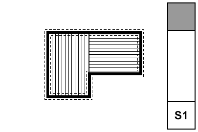
• Bearing Walls. To show a bearing wall, draw a fill on top of it. This is a non-associated, additional element. Use the fill '*Masonry Block', with a background pen of 50. Use the layer +S Struct Note. So: Walls are clear, except bearing walls, which are shaded.
• Rafters & Joists. Fill elements of the fill 'Joists 16OC' or 'Joists 12OC'. If you need other spacings, you need to make more fills. The fills go on the layer S Framing, which only shows in the framing plans. Rafter and joist placement is diagrammatic.
• Rafter & Joist Labels. Object 'Joist Note JAM9'. With the joists shown as fills, you don't need to show the extent in the note object, although it has that option.
• Beams. Beams should generally be modeled and labeled in sections. Use the objects Wood Beam JM9 and Steel W Shape Beam JAM9, etc. Most beams should be on the layer S Beam, which shows in section. If the beam is just used as a note, place it on S Framing.
Beams can reference their calculations by use of the ID tag in the objects.
• Annotations. All annotations should go on the layer +S Struct Note, unless you want an annotation to show in the foundation plan simultaneously. In that case, use +S Note All. Use a background of pen 91 on text blocks to make them readable when placed on fills.
• Structure Notes. Loads, criteria, etc. are part of the General Notes PDF. Specific notes can be added to the plans using text blocks.
All these are set up in the templates and favorites. If you notice Arial anywhere, you are missing a font on your system. If there's Arial and you don't notice it, consider getting a job using AutoCAD.
Notes & Labels: Lucida Sans
Dimensions: Tahoma
Drawing Titles and Plan Titles: Times
Drawing Number in Title: Futura
Drawing List: Lucida Sans
Room Name: Times
Sheet Number: Futura
Title Block Data (Except Firm Name): Ocean Sans Std Light
Title Block Firm Name: Times
Project Title (Cover Sheet): Goudy Old Style
Starting with AC 10, we will use 'real' section markers.
When we started with AC 5.1, there were fixed section marker styles. (Like the fixed dimension ticks and arrowheads to this day.) We didn't like the available styles, so we adopted the policy of showing sections in plan with an object, independent of the SE cutting element. The independent object also means we can fudge the placement of the marker, rather than being bound to its actual extent. And we can have that two-headed marker option.
In 8 (I think), they instituted GDL section markers, so we can in principle make markers any way we want. In practice, scripting SE markers is rather quirky, and I decided to punt, waiting to see if it would improve.
The main disadvantage of the independent object is that you need a workaround to refer to the drawing in the set.
In 10, they have overhauled tweaked the reference method internally. It's mostly good, but the workaround linked above is actually made worse. I can't take it anymore.
And no, the scripting is still weird. In 10, SEs have visible hotspots that aren't detectable. Gimme a break. But on balance the time is now to switch to real sections.
Summary.
Object Pros: Total scripting control. Flexibility in graphic placement. Cons: Awkward drawing referencing. People think we're weird.
Real SE Pros: Unity. More intuitive, not fighting the program. Automatic referencing. Cons: Less graphic flexibility.
Standards and template updates are below the fold.
This isn't a new layer so much as a fork of the old A Roof layer.
In AC9, as everyone knows, model polygons can have a cover fill. This means generally much less drawing, and more showing of those model elements in plan. It also gives the opportunity to 'stack' model elements in plan using Display Order (Send forward/back.)
In AC8.1 and earlier, you might have placed a counter slab on a A Cabs3, and a fill on A Cabs2, now you can have just the slab on A Cabs2. This promotes unity.
This ability, of course, extends to roof elements. It is possible, with some work, to show a roof plan built from actual roofs. This technique will have its own post.
Where we used to have one layer for roofs, because they were all 3D-only, now we have two, so we can choose to show roofs in plan, or not. We maintain the pattern of other 2D/3D layer pairs: Deck2/Deck3, Cabs2/Cabs3, Stair2/Stair3, etc.
(This is for AC9. 10 is here.)
What happens when the existing drawings are done.
The basic idea is to keep the existing conditions, both the PLN and the layout book, tucked away safely. It is theoretically possible to get existing drawings out of the addition project, but it's more trouble than it's worth.
I will use a new home in this description. Existing drawings are very similar. Warning: This is a whopper.
(So Jon says, where's the existing template, and I tell him, and he says I looked online and I didn't see that, and I said, well I'll fix it, so here ya go. The library names were wrong too!)
1. Duplicate the zTemplate folder and rename it with the project name. To duplicate a folder, drag and drop it within the same window while holding down the Option key. Use the client name. If this is a second, or later, project, add a number. (Please don't use roman numerals, they are hard to read.) If it's a sub-project or related project, add a descriptive term. Examples: Stevens. Kernan3. Salamander Garage.
2. Open the project file template for new home or addition. The template names end in .tpl. The new template is at the top of the project folder. The existing template is in the '4 Site & Existing Conditions' folder.
3. In the library manager, make sure you have 'Archicad Library 9.pla', '1 Rill & Decker LIB9', and '2 Project LIB9' loaded. Click 'Library Cache Settings' and make sure 'Use a Local Copy' is UNchecked. Click 'OK' and 'Done'.
4. Once the libraries load, Save As. Format: Archicad Project File. For the name use the client name, similar to the folder name. For an existing house use 'Existing Somebody.PLN'.
5. Go to the Finder and delete the project templates from your project folder. They are no longer needed. If by some weird chance you need a template again, you can always get it from the zTemplate folder.
6. Get busy!
Alphabetical by name of thing. Please suggest improvements and additions. Note: I change the date whenever I update this, so it will pop up every now and then. Rest assured it's not all new. Big changes will have a post of their own.
Changes in this update: S Wall layers, the fireplace stuff, A Roof2 (roofs in plan), CenterLine & CenterPoint objects, gross area calculation, room name object moves to A Zones.
The Interactive Schedule settings used by your local Archicad are saved as .iss files in ~/Library/Application Support/Graphisoft/IS Settings.
('~' means home, the house-looking folder named after you.)
But you don't actually use them there, so that's just FYI.
The standard IS settings, for the techniques I will describe here as they become available/I have time, are at 3 Resources (Onion)/Interactive Schedule. You use the IS interface to get these into your projects. Either: Calculate -> Interactive Schedule -> Settings...; or Calculate -> Interactive Schedule -> Preview..., and then the 'Import Settings From...' button. I prefer the second method; you can get from Preview to Settings but not the other way around, and I don't know why you'd fiddle with IS settings and then not want to see the schedule. (Maybe I'll just take that Settings menu item off. Let's move on.)
You can import multiple .iss's at once.
While it is possible to Change the Settings Folder, I would like explicitly forbid that you do so. Especially, don't use the 3 Resources/Interactive Schedule folder directly. If you do so and then make changes, you are Messing Things Up™. By keeping all the schedules settings local, you can mess them up all you want, as you need to, and you can always re-import the standard ones. That is, feel free to experiment.
I'll point out in passing that IS settings are handled very similarly to Work Environment schemes, and differently from attributes and library parts, and differently from conventional list schemes, which aren't library parts but are in the loaded libraries. It's really insanely complex. Maybe someday there will be a unified external asset manager for all this stuff, and the view sets too. And the display options.
As of, I don't know, 8.1, Display Options can be organized into Combinations, kind of like layers, and Display Options can be saved with views. Our templates have been set up this way for some time, but I don't think I've ever cataloged the combinations. They're just as standardized as anything else. Highly.
In the DO dialog, there are two panes, Display Only and Display & Output.
The Display Only options do not vary among combinations. Real quick: Intersections are on, Walls are contour lines, all the handles are on, section depths, detail boundaries, and markup elements (never used 'em) are hidden.
Display & Output options is where the action is. Rather than describe each combination, or heaven forbid build a table, I'll describe the A1/A2 combination, then how the others differ.
In A1/A2, which gets saved with plans and elevations for output: Beams are Contour Lines (no reference lines), Line Weight is Hairlines (they get turned True in PM), all the Fills are Vectorial, Doors & Windows Show with Dim, Zone Polygons are None, Zone Stamps Show, Section Markers are As in Settings, Column Symbols Show, Fill Background Color is By Element Setting.
Working Plan/SED is the same as A1/A2 except Beams are Entire Beam (ref lines on), and the Drafting and Cover Fills are Bitmap.
A3, which gets saved with wall sections, is the same as A1/A2 except the Fill Background Color is Transparent. (This means no fill backgrounds. Use Solid Fill for white masks. To mask with a pattern fill, you need two overlapping fill elements.)
A4/S0/M/P, which gets saved with RCPs, mechanical, plumbing, and foundation plans, is the same as A1/A2 except the Doors & Windows are Reflected Ceiling.
S, which gets saved with framing plans, is the same as A4/S0/M/P except the Cut Fills are Separators only. This turns the wall fills off, but shows a line at the joint between, e.g., concrete and stone. Fill backgrounds are on, so masking fills will work.
Site, which gets saved with site plans, is the same as A4/S0/M/P except the Cut Fills are No Fills. You will only see the effect of this if you show walls on the site plan.
A quirk of DO Combination management: You can't rename them. You have to Save As, which leaves the old one in place, and then you have to redefine the views that use the renamed combination. Then you can delete the old-named one. Also, I haven't figured out how to import DO combinations from other projects.
I usually keep S/E's set to Auto-rebuild.
• S/E Element Placement. Marker ends should not extend too far beyond the building itself. Our section elements go on a non-printing layer, and we use a separate object to show the section locations in plan. This is because it is difficult to reconcile the extent of the cut with the desired graphic presentation of the markers. That is, To get the markers looking nice you need have them much more extensive than is required to create the view itself.
Cut sections using the section marker Plain Section JAM9. This simple marker just shows the ID and a flag to indicate direction.
Elevations should be as close to the building as possible; the marker should be stepped where necessary to achieve this. Watch out for eaves and gutters.
Sections often require a lot of tweaking to get them to cut through interesting/clear/consistent stuff on all stories. Watch for undesirable effects of stepping with respect to roofs. Where a section cut is perpendicular to a roof's slope, try to avoid stepping the section within that roof. If you can't avoid it, discontinuities in the roof can be patched, but the patch becomes a maintenance issue if you edit the S/E element again.
Section depth should be minimized in order to improve performance. The depth should reach only the most distant element you want to see; usually it's a ridge or a chimney. Infinite depth sections should never be used. Zero-depth sections come in handy sometimes for generating details, but building and wall sections should always have some depth. Section depths are typically off in display options; toggle them using Karl's marvelous add-on.
• Layers. All annotations go on the layer +A Arch Note Reg Scale. This includes text, arcs and splines used for leaders, and notation objects. All added 2D work should go on +A Misc Line, but this is not a critical issue. Since S/E windows usually only generate a single view, layer discipline is not as important as in the plan. You should, however, make consistent use of the Arch Note layer, to maintain the option of turning the notes off to display the S/E image by itself.
• Vectorial hatching.
Elevation (and 3D) hatching is generated by the 'Vectorial Hatching' setting of the material in Options -> Attribute Settings -> Materials. The pen of the hatching should typically be 150, which is light gray.
Display of the hatching is a setting in the model tab of the S/E element itself. Hatching slows down generation considerably; in typical use it should be off. Before publishing, turn the hatching on for all the markers by selecting all of them and checking the box in the info box. The hatching switch setting is not saved with views, which is too bad.
• Unwanted lines.
Ugly bits which are complex can be patched. To hide simple cases of a few unwanted lines, use a fill which matches the vectorial hatching of the elements involved (shingles, stone, etc.), and has an opaque background. For blank walls you can use a solid fill of a white-printing pen. I use 80, which is purple, so I can see the areas I've masked. Masking fills and patches should go on the layer +A Misc Line. The use of masking elements becomes a maintenance issue.
• Rendering of depth.
Foreground elements should be outlined with a heavy (5-weight) polyline. There is no reliable way to do this automatically, it's tedious. One tip: for symmetrical building parts, outline one half and then mirror. Another: Outlines can often be copied and pasted to the opposite-facing elevation and mirrored across the origin.
Use Marked Distant Area where appropriate. When using it, check 'Use One Pen' and use pen 30. Pen 30 is gray in AC and 1-weight black in PM. You need section depths on in display options to edit the MDA depth. Don't forget the shortcut.
When you combine outlining with MDA, you get three levels of rendering: Fills on and outlined, fills on with no outline, and fills off.
• Model pens. Except for walls and objects, elements are drawn in 3D with their floor plan pens. Walls have a dedicated 3D pen, which should be a 3-weight. (Typical walls are 13.) Objects can have a separate 3D pen, either as a parameter or hard-coded, this will vary. It is a long-standing wish that all elements have a separate 3D pen.
• The ground. The ground mesh section settings should be: Fill='Air Space'; Background pen=91; Cut pen=6-weight. (I like green land, so 36.) These settings give an invisible fill with a heavy ground line. The bottom and side lines of the mesh should be obscured by the object Grade Mask JAM8, which goes on the +A Misc Line layer.
• Annotations.
Elevation notes. The main materials and building elements should be noted. This includes wall finishes, trim parts, decorative columns, panels, railings, chimneys, etc. To align the notes, use the object Note Column JAM9, in the drawing tools folder. Notes on the right side should be left-justified with the leaders starting at the first line. Notes on the left side should be right-justified with the leaders starting at the end of the last line.
It is permissible to fully annotate one elevation on each sheet, and then only point out unusual features on other drawings on the same sheet.
Levels. Use the object 'Elev Marker JAM8'. Elevation views should show the Z-height of each story. It is helpful to draw a dotted (not dashed) line through he elevation at each floor level. Dotted lines need to be heavy in order to be visible; use a 4- or 5-weight. In sections, levels should be should be shown for ceilings as well as floors, and for interior floor level changes (such as garage slabs). Level objects will auto-display their Y position, which is the height. They should be dimensioned to show the relationships among them.
Knee wall heights should be dimensioned in section.
In sections, unusual ceiling or floor conditions may be labeled with Slab Elev JM9. Examples: Lowered ceilings in small rooms, a stepped slab in a theater.
Roof pitches should be noted in section and elevation with the label Roof Slope JAM9.
Doors and windows should be labeled with Door-Window Label JAM9.
Structural members in section should be labeled with Description JAM9. Joists are shown 2D-only using 'Joists Sect 2D JAM9'. Our standards don't support modeling the joists.
F Trim2 is for trim elements you want to show in plan. Two applications off the top of my head:
• Pilasters. This gives the option of turning off the pilasters in structure plans, etc.
• Panel Walls. Where you have pilasters, you often have paneling, and if you show the pilaster without the panel you get a gap.
Alright that's only one application. One and a half maybe.
I've made a couple of changes in the templates which affect how columns are layered. These changes are important, especially if you are in the habit of placing architectural columns on the S Column layer.
1. S Column no longer shows in architectural (A1) plans. With this change in mind, I also want to clarify the difference between architectural and structural columns.
2. There's a new layer, S Col Steel, for columns in the basement that need to show in the foundation plan.
If you come to me and ask why your columns are missing, I'll know you didn't read this.
Another Hotfix. It's on the Onion, next to the previous one. Here is the list of fixes. I was tragically victimized by the disappearing label thing, so good.
Again, Everyone should run this. Again, You can run it from the Onion, rather than copying it to your machine.
Again, (You can check for updates any time by choosing Check For Updates from the Help menu in Archicad.)
I love the clipboard. I won't paste in my rant about the version numbering, although it still applies. Yup, 9.0.0 v1, now and forever. Watch that build number though.
These are the primary functions of layering, in order of importance:
1. Control of display for output. The finished output has to show and hide the right elements.
2. Control of display for working on the project. Showing and hiding elements depending on the work you are doing at the moment.
3. Promotion of logical thinking about the project as a building rather than as a bunch of drawings.
4. Protection of elements used for reference. For example, the walls are locked when working on the structure plans.
Layers exist so elements can be shown, hidden, and locked as needed. Beyond that, layering helps keep the project straight in our minds as we work on it. To this end, layers should be:
• Sensible. An architect using an architecture-oriented CAD program should expect to find a layer for "Walls". They would also expect a layer for fireplaces, even though walls and fireplaces display together and don't technically need separate layers. "Put the fireplace on the wall layer" doesn't sound right. In keeping with Virtual Building principles, our layers relate to building parts first, and annotations or drawing types second.
• Truthful. I recently added a layer, S Deck, for floor-structure slabs. Previously, we used S Slab. I decided it was poor thinking to call joist decks and concrete slabs by the same name. Layers should encourage clear thinking about the building itself.
• Logically Consistent. A stair will be made of elements which display in plan and elements which are 3D-only. So we have two layers, A Stair2 and A Stair3. This arrangement should apply to all assemblies which are split between plan and 3D, such as soffits.
Here's another way of looking at it:
In the design of Archicad, the floor plan is the "main" window. Close it and you close the file. Every element must be on a story, and therefore visible in the plan window at some point. (Even though you can place elements in 3D.)
The first function of layering is to separate the Plan- and 3D-only elements. If we only did architectural drawings, we could get by with just those two layers, Plan and 3D. We would have two layer combinations, Plan, showing only the plan layer, and 3D, showing both layers. This setup meets the minimal display requirement above.
But it would be very difficult to work with. Productivity would suffer as the user went insane. So within the architectural, we have lots of plan layers and lots of 3D layers, which correspond to building parts. In the plan we have walls, cabinets, fixtures, etc. In 3D we have floors, structure, trim, etc. The addition of these layers doesn't advance the display requirement at all, it just helps us stay sane.
It helps our work to have layout and guide elements. Those need layers, since they have to be hidden for output. It's convenient to be able to "permanently" hide elements without deleting them, trashcan-style. It's handy to keep area-measurement fills in the project, but we don't look at them very often. So there are several kinds of administrative layers that don't directly represent the project or the output.
Then there's the invisible modeling tools, cutting roofs and SEO operators.
Once we get into other drawing types, structure plans, etc., those drawings have their own annotations, and require different architectural elements to be shown and hidden. The structure plans require that the landscape walls (hide) be separated from the architectural walls (show). The reflected ceiling plan requires that the crown moulding (show) be separated from the other high trim (hide). If you have two site plans, you need layers for each of their annotations, and for the annotations they share.
The layer setup we have is the product of a years of refinement along these principles. When we add a layer, it should be in order to improve the logic of the system or to facilitate a new/better mode of work. For example, to model wall sections, the crown needs to be positioned taking the ceiling finish into account, and the ceiling finish itself needs to be modeled. But since the ceiling finish is only useful for wall sections, we don't take the time to build it everywhere. Since it stops and starts, it needs to be hidden in building sections so we don't have jaggy ceiling lines. Therefore we need the layer F Clg Fin, as well as layer combinations for wall sections separate from building sections.
I hope this helps answer the question, "Why are there so many layers?"
The Work Environment offers the ability to export the keyboard shortcuts as a web document. So why not. Here it is. This link will stay on the Standards section of the sidebar over there on the left. If any of these don't work for you, you can import the current shortcuts from 3 Resources / AC / Work Environment / Rill [version] / Shortcuts.
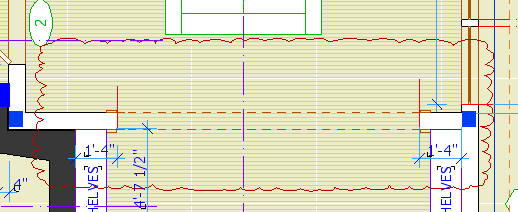
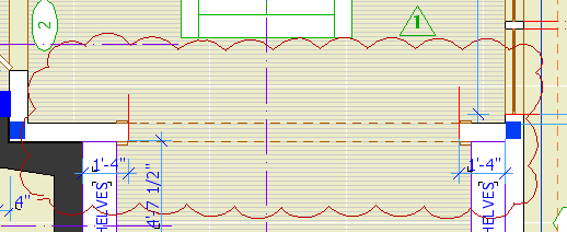
A Flue is for modeling chimney flues. It shows in plan and section. In section, the layer should be wireframe to show the flue void. In general use, elements on the A Flue layer will be subtracted from each part of the Fireplace/Chimney. The templates have a new layer combination, 'View Flues', which shows the flues solid inside the wireframe chimney.
A Chimney3 is for chimney parts that should not show in plan. Formerly we used A Wall Hi for this purpose. Putting these elements on their own layer allows you to show an axonometric of just the chimney. The templates have a new layer combination, 'View Chimney', which shows the chimney solid by itself. You can use a marquee to create a cutaway axon to show the flues.
Everybody knows this, right?
Do not use the "Cloud" objects in the Archicad library. They are the worst objects in the world. Update: I killed these with my bare hands. They're gone and you needn't fear them any more.
Clouds should be drawn with a closed spline using the "cloud" linetype. The only glitch is that sometimes the cloud will be inside out when you are done. If this happens mirror the cloud, or, if the shape is non-mirror-friendly, draw the spline again, in the opposite direction. Sometimes the spline doesn't quite close. Pretend not to notice.
For the triangle, use the object Character+Shape JAM8 Shape Tag JM9. The number comes from the ID.
Bad cloud. Looks like a chunk of foam rubber from an AirTran pillow. Also missing marker.
Pretty cloud, reminds one of heaven.
Current naming standards. Still very boring.
These rules aren't set in stone, but if we all stay near the rules we all stay near each other. Like all standards, they work MOST of the time. If a situation is addressed by the standards, save your creativity for the projects.
Every drawing or set we give to someone else should be archived as a PDF in the project folder at 2 Output : PDF Archive. This is for convenience and our own protection.
Archives should be named with the date, and a description if the set is for a specific purpose, such as a permit set. Example: Somebody 2005-03-11 Permit.PDF.
In OS X, PDFs can be created from any print dialog by clicking the Save As PDF button.
PDFs saved in this way will be single files with all the printed sheets in them.
You can use PDFs to send drawings to consultants, if they just want to view the drawings and don't need CAD data. If they need actual drawing stuff, you need to send DWGs.
You can view drawing set PDFs using Adobe Reader or Preview, the OS X PDF viewer. Preview is generally better.
(I solved the screenshot problem by taking fewer screenshots.)
Pen table in Archicad...PM...
• Most work is done using the typical rows. The first pen is thinnest, at 0.04mm. Each sucessive pen is slightly thicker, up to 0.8 mm. The pens darken very slightly from left to right. The color change should not be apparent in general use.
For typical rows, the pens ending in the same number are the same weight. 11, 21, 31, 41, etc are all the same, they all turn black in layouts, where you can't tell them apart. Use the colors to differentiate parts of the model. Within the colors, set the line weight. Be consistent in what colors you use for different purposes. These are my habits:
Walls: Black (10's)
Roofs: Cyan (80's)
Doors & Windows: Brown (20's)
Soffits & Ceilings: Orange (60's)
Panel walls: Yellow (110's)
Counters: Purple (120's)
3D stairs, decks, terraces: Dark Red (50's)
Appliances, fixtures: Green (30's)
Main crown: Pink (70's)
When using the same color for different types of elements, make sure the types are spatially and conceptually separate. You can use your roof color for trim, but if you used it for ceilings it would get confusing.
For trim elements, use a different color for each type. I make the main crown pink and the baseboard dark red. If there's a chair or picture rail, I'll use cyan. This makes it easier to tell them apart when they're all stacked together.
Many CAD standards use color to represent output line weight. This is a help to drafting but is useless for model building. The most important issue for us is maintaining order and telling what is what. By using matching color for the plan, section, and fill pattern pens, the element will be recognizable from any point of view.
Fill patterns in section (brick, stone,etc) should have pen 11 (or 21, 31, 41,...). Composite separators that aren't set to hide should have pen 12 (or 22, 32, 42,...). Use a 13 (23, 33, 43,...) weight pen for edges in plan, such as counters and stair treads. Weight 15 (25,35,45,...) is used for cut elements in plan and section. I didn't forget 14 (24,34,44,...), it's used for the cut pen on elements that are either thin, curvy, or small, making the 15 weight seem too heavy.
The heavier pens in each row are there if you need them. You usually don't, and having so many is overkill, but we don't need the space. I use pen 36 instead of 35 for the cut pen of a site mesh, so the grade line is heavier.
The last pen of each typical row is consistent in color but not in weight. Each n9 pen is 0.2mm thicker than the previous; 19 is 1.0mm, 129 is 2.8mm. See image.
• Pen 1 is black. It has the same weight as pen 15. Pen 2 is an anomaly, we shouldn't use it but we do. It has the weight of pen 13. We use it for structural slabs and decks in plan. In section, these slabs use pens 11 and 15.
• Pens 3 through 9 are used for differentiating things that don't print, and therefore don't need a particular line weight. Especially S/E elements. I organize my sections like this:
Exterior elevations: 9 (purple)
Long sections: 4 (green)
Cross sections 3 (orange)
Interior elevations: 6 (cyan)
Wall sections: 7 (blue)
Sometimes you have to cut a section just to generate a detail; I use pen 5 (dark red) for those.
Pens 6 & 7 are used for dimensions. They have special weights and your dimensions won't look right with other pens.
• Multiples of ten are an odd group. They used to be mostly white, but lately we've found the need for several dedicated pens, and this is where they are.
Pen 10 is the primary guideline pen. It is white in PM.
Pens 20, 40, 60, and 80 are all white in PM. I use 20 for junk sections, and 80 for white masking fills. Use these pens for anything you need to see but not be distracted by, or anything that needs to print white but be visible in Archicad.
Pen 30 is for the marked distant area of a section. It is gray in Archicad, and plots as a fine black line. When using marked distant area, always "Use One Pen" and choose pen 30.
Pen 50 is the dedicated poche pen. It should be the background color of most cut elements in new construction.
Pen 70 is light orange, and is intended for beam centerlines. The default was white, but they were hard to see. It plots white, and the display options turn the beam centerlines off for output anyway.
Pens 90 & 110 are white. They don't have any particular purpose as of yet. Don't use them. When you need a white pen that's white, use pen 91. It will never change.
Pens 100, 120, 140, 160, 180 are part of the grayscale pens.
Pen 140 is a thick, white pen for making wall-masking hatches for structure plans. More on this later.
Pen 150 is for material (surface) fill patterns. This means cover fills, 2D floor finish fills, and the vectorial pen of materials.
• Pens 141-149 match the weights of a typical row, but they plot at 50% gray.
• Pens 91-100, 111-120, 131-140, 151-160, 171-180 are the grayscale pens. They plot as they are seen in Archicad.
Again: For white white, use pen 91, and no other. Also, never change the color of pen 91. The whiteness of 91 is deeply embedded in Archicad culture. Most (all?) library parts with white in their symbols use this pen, because it's a given that no one will change its color. Other white pens, you can't be sure. Eg, pen 30 used to be white, now it's not.
• Pens 161-170 & 181-255 are not used. Archicad provides 255 pens for compatibilty with AutoCAD; it's really too many. Pen 255 is black in case you put in a pen number greater than 255 by accident, which gives you pen 255. If this pen were a color, it would print in color, causing your plots to have gray lines.
• Switch the title block to the RND9 version. Required. Use Cmd+Opt+click on the new object to retain settings. This is very important. If it fails, that is, you get the new object with default settings, cancel out of the settings box and try again. Delete all the hotspots. Place new hotspots in the sheet number box and the corners of the main drawing area.
• The grays as they come out of the new plotter are all darker. This affects the gray poche in the walls, etc. and the gray lines we use for floor and material fills.
The poche is a little dark, but we can live with it. If you change it it will look better, but it's a chore: You must change the fill background color of all 3D building elements (walls, roofs, slabs), and the background color of all the skins in composites whose settings are used in elements, and the fill color/background color of any masking fills, and the fill color/background color of any objects that show poche in plan or section, keeping in mind that some of them have special parameters for these fills. A chore. If you choose to go through with it, use pen 50. This is our new, dedicated poche pen. The idea is to make the next gray revision simpler; with a dedicated pen, we can just change the color of it rather than the settings of dozens of elements. I wish I'd thought of it sooner. So, poche pen change: Optional.
The fills, however, aren't quite OK. They should be changed to pen 150*. Strongly recommended. The fills include:
1. Fill elements, many of which will be on the F Floor Fin2 layer. Use find and select, on each story, for fills with pen 93.
2. Cover fills on 3D elements, including slabs, roofs, meshes. Do this in the 3D window to get all the stories at once.
3. Vectorial hatching pen on materials. You have to do each material separately in Options -> Attributes -> Materials. (Attribute Manager doesn't work for this.)
• In addition to the grays being darker, all the line weights are heavier, so we need to make all our pens slightly thinner. You will have to do this by hand in PlotMaker. In Archicad, you can use Attribute Manager to import the pens from 3 Resources : Attributes : Color Pens 0105. Required.
All the changes discussed above will be made in the templates.
*UPDATE: This used to say 92. 92 is the right color for plotted output, but in Archicad it looks too light on the screen. Read this post about the new material fill pen. As for changing the pen, either 92 or 150 will work in PM.
One more change resulting from the new plotter: To go along with the dedicated poche pen, 50, we have a dedicated Material fill pen, 150. On the same principle as the poche pen, this gives us specialized control over the material fill color without changing a lot of settings.
I thought 150 and 50 kind of went together.
The pen is set to print in PM with the color of pen 92 (90% Grey), and display in Archicad with the color of pen 93 (80% Grey). The weight is 0.15mm, the same as 92, 93, and the rest of the <50% greys.
This pen is intended for vectorial hatching on materials, cover fills representing materials, and fill elements representing materials, such as floor finishes.
The templates have been updated. To use this pen in current projects, you must:
• Change the color and weight of the pen in PM (Options -> All Pens And Colors) and Archicad (Options -> Attributes -> Pens And Colors).
• Change the Vectorial hatching pen of the materials.
• Change the fill pattern pen of elements with cover fills.
• Change the pattern pen of floor-finish-type fills.
Remember: With the new plotter, 93 is really too dark for these fills. You should change the pen. If you've already changed a project to use 92, changing to 150 is optional. If you haven't changed yet, use 150.
There is a bugfix, they call it a Hotfix, I don't know what that means, update to Archicad. The updater is on the Onion in Archicad Program Files. It's called AC9-1965.
Everyone should run this. You can run it from the Onion, rather than copying it to your machine.
(You can check for updates any time by choosing Check For Updates from the Help menu in Archicad.)
Here is the list of fixes. Most of them don't mean much to me, hopefully some of our (unlisted) issues have been fixed too.
It has been out for several days and no one has complained yet, so it probably does no harm.
Graphisoft's version numbering scheme has become completely ridiculous. Patches like this one should increment the third digit in the version number, making this 9.0.1. But no, they have this quirky "v1, v2" patch numbering deal, but they don't even use that consistently. Sometimes a patch increments the v number, sometimes it adds a "+", and in this case it does nothing, it's still v1. So it's not 9.0.1, it's not 9.0.0 v2, it's not 9.0.0 v1+, it's 9.0.0 v1 Build 1965. You have to know the build number, which should be a really geeky arcane thing, in order to describe the standard current release of the program. Most people outside of software development don't know what a build number is. Ridiculous.
The "General Faves" have been updated with the new poche pen for all the model elements. If you are going to change poche pen color in a current project, and you use Favorites, you should load the new version.
Since we got a new plotter, we need a new title block. Makes sense to me.
Before printing from the new plotter, you must switch to this title block object. When switching, hold down command and option and click on the new object. This is very important so you don't lose your old issue dates. If you try switching and it doesn't work, cancel out of the object settings and try again.
The object looks the same, but I took the opportunity to fix/add a couple things.
The overall size of the object, including the margins, is the same as the paper in the layout. In the previous version, the size matched the printable area. When changing an existing project, make sure the lower left corner of the title block drawing is on the lower left corner of the paper. (The outermost rectangle, if you can see a difference, which for large sheets you won't.)
You can have up to eight dates instead of five. You can limit the number date spaces to four.
If the client name doesn't fit the title block horizontally, you can make the point size smaller (Custom Project Size), or put part of the name on a second line (More Project Name). Note: This parameter is separate from the Book Info. You can still use the Book Info for the other fields. That is, if you want the second line, you have to set it in Archicad.
I turned all the pens black, and lightened the gray on the square a little.
L Wall2 and L Wall3 are for landscape walls.
L Wall2 shows in the floor plan, while L Wall3 does not. L Wall2 is hidden in the structure plans. We want to see landscape walls in the architectural plans for clarity, but we want to omit them from the framing plans if the aren't in the main contract/permit.
This layer sort of "forks off" from the layer S Slab.
Use it for framed structural decks (TJIs, 2x12s, etc). Continue to use S Slab for concrete slabs.
Why? Because decks aren't slabs. Yes, they're both made with the slab tool, but layers represent project elements, not tools. As much as possible, layer names should represent real things.
Where does this leave the layers A Deck2 and A Deck3? Right where they were. Model the deck surface on A Deck3. Model the structure of a deck on S Deck. Place 2D elements representing the (architectural) deck on A Deck2.
[Slightly updated, really just bumped. Originally posted in April 04.]
Turn the Schedule Symbol off and leave it off. At the bottom of the settings dialog you'll see a division called 'Dimension Marker'. Click the flyout at the top and select 'Door[or Window]TagJAM9'.
Why do it this way instead of the old way? Because the display of these markers is a display option. To show the markers, choose 'Show with Dimension' under the doors and windows display option. To hide them but show the swings, choose 'Show on Plan'. This allows you to show the swings in the electrical plan without the tags.
One glitch: For JAM8 windows, if the door/window is in a mirrored wall, the symbol will go to the wrong side. Mirror the wall segment again to fix it, or just drag the tag. The JAM9 windows won't have this problem.
The modules for the assembly types (3 Resources / Modules / Assembly Types) and building parts (3 Resources / Modules / Building Parts-Existing (or) New) have been updated for AC9.
The layers have been updated and a couple objects modernized. And, thanks to Jon, the counter and cabinet depths are correct.
If you're not using the keyboard to switch tools, you're not living life to the fullest.
Chosen for convenience, the "main" tools:
` : Marquee
1 : Wall
2 : Slab
3 : Roof
4 : Column
5 : Beam
6 : Mesh
Note that these are in a row. The Arrow Tool is still the Right Arrow key. Esc will switch to the Arrow Tool if there's nothing else for it to do.
Chosen by initial:
W : Window
D : Door
O : Object
F : Fill
L : Line
Chosen for position:
E : Text
Opt+E : Zone
Chosen for appearance:
0 (zero) : Arc (Key has an arc and an ellipse!)
7 : Polyline ("&" resembles a polyline?)
8 : Spline
. (period) : Hotspot
[ : Section (get it?)
] : Detail (Goes with section.)
/ : Dimension
Arbitrary, but grouped nicely:
, (comma) : Radial Dimension
; : Level Dimension
\ : Angle Dimension
Modified initials:
Opt+L : Label
Opt+C : Camera
Other:
M : Lamp
Note: The only modifier key used is Option.
No key, tool rarely used:
Wall End, Corner-Window, Skylight, Stair, Figure.
If I haven't made this clear, I would like everyone to move their 8.1 projects to Archicad 9 as soon as is convenient. The transition is virtually painless. Ask for help if you need it.
In honor of AC9, I renovated the project folder scheme. The old one had too many divisions at the top, and too many squirrelly folders, e.g., 'Reference'. I mean, what is that? I also thought it was wise to promote the layout book to the top level, which left the CDs folder somewhat bereft.
So here's the deal. Discussion is welcome.
In PlotMaker 3 (and above), you can place special tags in text elements which can intelligently display information about the project, the layout, the drawings, and the system environment (e.g., the date). This functionality, and the tags themselves, are known as AutoText.
AutoText tags must be in all caps, and they must be inside greater than/less than brackets.
When viewed in Archicad, tags will always appear with their name. In PM, the tag is interpreted and the proper text is displayed.
The main categories of tags are:
� Info about the placed drawing,
� Info about the layout,
� Info about the system environment and the project files,
� Info about the project itself, as stored in the 'Book Info'.
We already use AutoText tags in our drawing titles. They appear as "DRAWINGTITLE" in Archicad, then display the proper drawing number, depending on the arrangement, in PM.
AutoText is also used to generate the sheet numbers in the layout book. In the place of the number on the master layout, we have the tag "LAYOUTNUMBER", which is interpreted in each layout according to each subset's settings.
The "LAYOUTNUMBER" is placed directly in the layout using the text tool. To see how it works, go to a master layout and activate the text tool. Click to start the text, then right-click and mouse over 'Insert AutoText...' The flyout contains all of the AutoText items. Select 'Layout Name', then close the text. Switch to a layout that uses that master, and you see the text has turned into the layout name. (In master layouts, layout- and drawing-specific tags will always be interpreted as 'Undefined [Something]').
The defaults for the following parameters the the main title block object have been changed to their respective AutoText tags:
• Project Name
• Type
• Street Address
• City
• State
• Zip
The SK title block uses AutoText tags in the Project Name and Type fields.
That means, new placements of the objects will have these values unless you change them. That means, you need to fill in the book info for the tags to be interpreted correctly (recommended), or edit the settings to display the info the old way. (But why?) Current projects should not be affected, but feel free to set up your book info and use the AutoTexts if you like. If you are going to issue SK sheets, this will make it much easier.
The templates have been updated with the new defaults. The 'Starting a Layout Book' workflow procedure now includes adding the book info.
For new projects, you must set up the book info, or you get this:
Wow, that makes 'Somebody Residence' look positively elegant.
SK sheets are the official format for issuing corrections, clarifications, changes, and other additional information after the construction set is issued. SKs become part of the construction documents, and should created and maintained with the same care as the big sheets.
Use an SK sheet whenever you have to issue document information between official revisions. Revision sets should be updated to include the SK information since the last issue. For geometry taken directly from the model, this will take care of itself via the traditional view updating process. Scanned drawings and other non-project-file info must be placed on an appropriate big sheet, in addition to the SK layout, so the next revision is complete.
We have developed a special title block for a letter size sheet, Title Block SK RND81. It enables you easily to create an SK sheet out of any geometry in the project.
The preferred method of putting out SKs is PlotMaker, using special layouts within the main CDs layout book. The layout book will automatically number the SKs as they are created, and keep them in one place for safety and organization. You can also import scanned drawings into the layouts, so that hand drawings can be maintained consistently with the rest of the documents.
It is possible to simply place a SK Title Block in Archicad, marquee the SK, and print the marquee area. While this method is quick, it does not create a permanent copy of the output, nor does it maintain your numbering. In addition, printing from Archicad does not have the same quality as printing from PM, since the colored pens have to be turned grey.
See also:
Title Block SK RND81
Getting the SK Layout Tools into Current Projects
M Fixt
Non-ceiling mechanical fixtures, such as floor registers. Shows in mechanical plan, or in the floor plan if you don't have a mechanical plan and you want to show the registers. (We did this on Stevens.)
M Fixt Clg2
Ceiling mechanical fixtures, such as ceiling registers or returns. Shows in mechanical plan and reflected ceiling plan.
M Equip
Mechanical equipment, such as furnaces, air handlers, water heaters. Shows in mechanical plan, electrical plan, floor plan, and section. If you don't want a particular element to show in section, turn the 3D off in the object.
Update for the Archicad 20 templates: The electrical fixture layers have new names that I hope are clearer to use. The strategy is the same.
E Symbol2, formerly E Fixt2
E Wall Fixture3, formerly E Fixt3
E Ceiling Symbol2, formerly E Fixt Clg2
E Ceiling Fixture3, formerly E Fixt Clg3
E Ext Fixture3, formerly E Fixt Ext3
E Ext Clg Fixture3, formerly E Fixt Clg3
Update again: I took the 2s and 3s off. Generally, symbols are mere symbols, and fixtures have a 3D component.
E Symbol
Wall & Floor fixtures, switches, receptacles; symbol only. Shows in Electrical Plan.
E Wall Fixture
Wall & Floor fixtures, switches, receptacles; modeled, display with symbols. Shows in Electrical Plan, A5 Interior Elevations, View Interior.
E Ceiling Symbol
Ceiling fixtures, symbol only. Shows in Electrical Plan, Reflected Ceiling Plan.
E Ceiling Fixture
Ceiling fixtures, modeled, display with symbols. Shows in Electrical Plan, Reflected Ceiling Plan, A5 Interior Elevations, View Interior.
E Ext Fixture
Exterior wall fixtures, modeled, display with symbols. Shows in 1/4" Elevations, Electrical plan.
E Ext Clg Fixture
Exterior ceiling fixtures, modeled, display with symbols. Shows in 1/4" Elevations, Electrical plan, Reflected Ceiling Plan.
Why do we need six electrical fixture layers? Read on if you're interested. I tried to modernize the names throughout but it got too confusing. The important principle is that new layers are often caused by forking an existing layer to meet new output needs.
Here's a new trim layer. It shows in the same layer combinations as the other 'F Trim'. In addition, it shows in the reflected ceiling plan, which is the point.
Place Crown Tool objects on this layer and you can avoid redrawing the crown for the RCP.
The layer has been added to the templates. Add it to current projects if you like. More on creating layers here.
I have added a division to the side bar for standards. It is a very narrow, highly refined subset of the standards category. You can't change this stuff.
Because:
They aren't architectural elements.
They interfere with the display of other dashed line elements such as soffits.
The footing line right next to the furring wall line looks ridiculous.
So:
Define the footings using details on the assembly types page. Show them on the structure plans, and call them out by type.
Send PLT files to the plotter using PlotFlow. Some day, we will be able to run it on the server. Currently, everyone has to run it locally.
One or two check plots may be sent directly to the plotter. Any more than that takes forever, during which time you can't do anything else in PM. Usually, create PLT files. Always create PLTs when giving drawings to anyone else.
I've created a new category here called 'Workflow'. In it I am placing howtos for the various project stages.
This category is so special that it has its own division in the sidebar to the left. (If it's not a link, it's not done yet.) Refer to it often.
With the Stevens project, we have started incorporating wall types, and other assemblies, into the construction documents.
Wall types are very circumscribed details showing what a wall is made of. Once you have the types defined, you are able to use very brief notations in other details to specify the walls. They are more accurate and easier to maintain, because they are only drawn once.
Use detail windows for assembly types. Details must have unique IDs, which is OK in this case because the types should have unique IDs too. Here some examples of names and IDs I used for Stevens:
W1 : 2x4 partition (Wood #1)
W2 : 2x6 partition (Wood #2)
WB1 : 2x6 Wall with brick veneer (Wood & Brick # 1)
CS1 : 10" Concrete with 8" Stone (Concrete & Stone #1)
F1 : Strip footing (Footing #1)
F2 : Pad footing (Footing #2)
For scale, I have found that 3"=1' (4) is good for walls and 1 1/2"=1' (8) is good for footings.
As I have developed these drawings for Stevens, then for Prill, I have been creating modules of them at 3 Resources : Modules : Assembly Types. For your projects, merge each drawing you need into a detail window. You can, of course, modify these for your needs. As you create new assemblies, save modules! By definition, these drawings will be simple and broadly useful.
To call out wall types in wall sections, use the detail tool with "Assembly Marker JAM81".
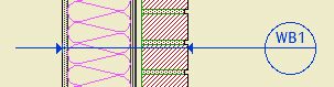
Like This
In AC9, the keyboard shortcuts are part of the Work Environment. They are stored at 3 Resources : Work Environment : RND Profile.
Keyboard shortcuts are customized at Options | Customize | Keyboard Shortcuts, Tools tab. The settings are saved in a preferences file called Archicad 8.1 Lasting.Prefs. The local version of this file is located at home : Library : Preferences : Graphisoft : Archicad 8.1.0 vn, where n is the current version.
Ours are fairly highly customized, and it's a burden for everyone to change them by hand. To save you the hassle, we keep a copy of the preferences on the server. (Quit Archicad before doing this, or no worky.) Simply copy the file from 3 Resources : Archicad Program Files : Good Archicad Prefs X : Graphisoft : Archicad 8.1.0 v1 : Archicad 8.1 Lasting.Prefs, and write over your local prefs.
Oops, it's not that simple. It used to be. For some reason, in AC8.1, a permissions issue has developed with Archicad 8.1 Lasting.Prefs, making it hard to copy. (The other prefs are OK.) Here is the workaround:
Duplicate the file in place. (Drag and drop it in the same window while holding down option.) You get "Archicad 8.1 Lasting.Prefs copy". Drag this file to your local prefs folder. Delete the old one. Rename "Archicad 8.1 Lasting.Prefs copy" to "Archicad 8.1 Lasting.Prefs."
Launch Archicad, and all should be well.
This is the official announcement.
At this moment there are 8.0 and 8.1 project templates in the zTemplate folder; kindly ignore the 8.0 ones until Monday.
Feel free to review these posts:
...along with any others that strike yer fancy.
I've added a module for Site Plan info to the Modules folder (in 3 Resources). It contains all the elements for contours, boundaries, notes, etc. I did not include separate note stuff for the 120 & 240 Note layers, but you'll probably live. N.B.: 8.1 only!
For AC8 projects, save PLC files on the hotel instead of on your local disk. This is a change.
The reason: In PM, you will need to link views from a PLC. A PLP won't work, and I wouldn't recommend it if it did. If the PLC is local, the layout book won't be able to find the drawings when opened from any other machine.
This change does not effect AC7 projects.
I have instituted 3 new standard layers. All three are used to hide things in the Structure plan that show in the A1 Plans, to help clarify the Structure.
+A Wall Mask: Fills matching the background color of the walls, to give a solid poché (sp?) effect. Formerly these were on an A WALL layer. Hiding these in S1 Structure keeps them from appearing in front of Structure elements.
A Deck Rail: Railings, posts, newels. Formerly these were on A Deck2. You may leave such elements there if they don't interfere with the Structure.
A Stair Rail: Railings, posts, newels. Formerly these were on A Stair2. You must use this layer. Note that the stair lines should display and remain on A Stair2.