
The reflected ceiling plan is a universal drawing type that Archicad simply does not handle very well. We took a medium-size step forward in Archicad 11 with addition of the 'Ceiling Plan' model view option for GDL objects. This allows object developers to make objects that draw themselves differently whether the 'Ceiling Plan' or 'Floor Plan' setting is active. But this switch only applies to objects, and beams, slabs, etc. don't know you want a different linetype when they're overhead as opposed to on the floor. Hopefully, this switch will soon apply to all elements, and we will have dedicated attributes for 'Ceiling Line Type', 'Ceiling Pen', and 'Ceiling Cover Fill'. I have wanted this for a while.
In the meantime, the RCP still demands a lot of tracing of modeled elements. It's better than it used to be, but it's still one of the least unified drawings.
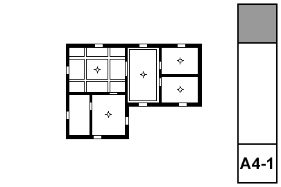
What shows:
• Walls
• Ceiling trim and finishes
• Ceiling fixtures including lights, fans, and mechanical fixtures
• Floor elements, including deck edges, stairs, counters; traced with a dashed line
(Yes, I copied and pasted this directly from the electrical plan post.)
The RCP shows everything on the ceiling, whether electrical or not. This includes trim, ceiling finishes, and HVAC registers. The electrical plan shows everything electrical, whether on the ceiling or not.
The plans should be separate if combining all that stuff would make a confusing drawing. If the combined drawing would not be too much of a mess, the two drawings can be unified as the RCP and the electrical plan can be discarded.
Our principals have the habit of red-lining electrical work on the RCP either way. Don't let this distract you from the right decision about using separate plans, or not.
• Door and Windows: Opening only, with contours. The openings appear empty.
• The 'Ceiling Plan' switch is on.
Elements on the A Ceiling All layer will show on floor plans and RCP. Place RCP Beam objects on this layer.
We have several objects designed to cut shapes into ceilings using Solid Element Operations. These include Filleted Box, Filleted Disc, and Soffit Cutter. The layer for these gadgets is X Ceiling Cut. They respond to the ceiling switch, and that layer is shown in both plans.
Ceiling trim objects such as Crown Tool and Trim Panel Ceiling belong on the F Trim Crown layer. This layer is shown in model and RCP, but not in plan.
All the tracing work goes on the layer +A RCP Line. Every tracing element needs to maintained: If you move the real beam, you need to move the lines.
The Working RCP layer combination shows the stairs, counters, roofs, soffits, and other elements you might need to trace. These layers are locked so you don't hurt things.
Often, you need to use real beam elements instead of an RCP Beam object. These beams need to be traced with a solid line. Slabs used as soffits, which might show in plan on the layer A Soffit2, need to be traced too. Tip: If you have crown tool objects along the beams, often they will imply the beam well enough that you don't have to draw the beam itself.
Floor elements should be traced with a dashed line. This includes stairs, countertops, and terrace edges. Providing this geometry gives context to the ceiling plan.
Roof edges must be traced. Clip lines (where a sloped ceiling meets a level ceiling) must be drawn. And both those lines should drawn dashed in the floor plans. But listen: Instead of drawing two sets of lines, place Ceiling Line objects. They're still redundant with the elements they represent, but you only need one instead of two. The object would go on A Ceiling All.
Tracing tip: Select the beams, slabs, whatever. Drag-copy them in place. Keep the selection. Switch the pen (n2), layer (+A RCP Line), and linetype (solid). Explode (Cmd+=), keeping drawing primitives only.
On a past project, I used actual beams on the +A RCP Line layer, rather than tracing. It's fine in theory; on that layer they would never show up in any model views. But it seems weird. If you did go that route, you would just drag-copy the beams, then change the linetype and layer. There is still the maintenance issue of keeping the beams and the note-beams aligned.
Special ceiling finishes, such as beaded board, should be drawn with fills. (If you are using the crown tool in coffer mode, the object can automatically show a ceiling fill. Check under the Plan settings.)
You also need to draw any paneling that isn't modeled, and any other fine ceiling detail.
All this stuff goes on +A RCP Line.
Annotations go on +A RCP Note.
Like any drawing, call out what needs to be called out. If there are important alignments in the ceiling involving fixtures, paneling, trim, etc., those should be dimensioned or otherwise noted.
It's sometimes helpful to note ceiling heights where they vary. For this you would use a level dimension with manual text. I have a label for dimensioning slab elevations, Slab Elev, but it's a bit awkward to use in RCP because the labeled slab has to be visible in order to see the label (LAME). In the project where I used this method, I made a new layer, A Clg RCP, for ceiling slabs that need to show in RCP. I don't know if that's worth it or not. Labels need a lot of work.
You can call out crown objects directly using Description JAM9. In the label settings, set Parameter to Label to 'crnDes' to have the label display the name of the moulding. Be aware that this will not include any backers or secondary mouldings.
If you have crown 'type' details, you can call those out by putting the detail name in the crown object, and using 'typeList' as the Parameter to Label. Of course, you can also use text labels or just text.