Updated for Archicad 25.

These guidelines are current as of Archicad 25.
Here is a method for keynotes in vanilla Archicad, except it doesn't work. It takes a classification, three properties, an object, and a schedule:
A classification called Keynote.
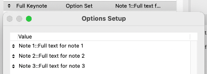
A property called Full Keynote, string type option set. Each option consists of the short note, a separator, and the long note. The separator can be anything that doesn't occur in content, such as "::". The short note is displayed in the view, as an object. The long note is shown alongside the short note in a schedule.
A property called Short Note, string type, using the expression SPLIT (Full Keynote, "::", 1). This property will output the short note part of the Full Keynote property.
A property called Long Note, string type, using the expression SPLIT (Full Keynote, "::", 2). This property will output the long note part of the Full Keynote property.
All three properties are available to the Keynote classification.
An object, maybe called Keynote Object, which acts like a label, with text and a leader. The text is the Short Note property. The objects are classified as Keynote.
A schedule of the Keynote Objects, which shows columns for the Short Note and Long Note properties.
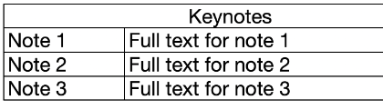
The format of the Full Keynote options is:
Note 1::Full text for note 1
Note 2::Full text for note 2
Note 3::Full text for note 3
etc.
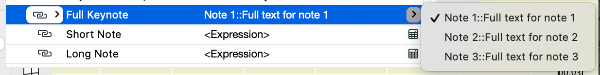
Options are created as needed in the Property Manager. The user places Keynote Objects and selects the desired Full Keynote property option.
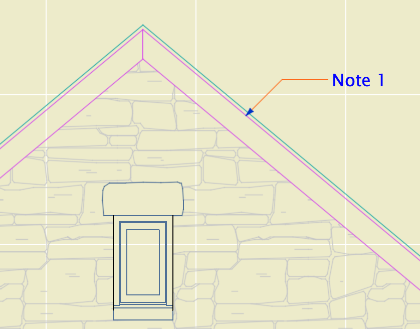
The object displays the short text...
...and the schedule lists all the notes.
The only catch is that only floor plan elements can be scheduled; the workaround for this is to make sure any elevation keynotes are duplicated on a hidden layer in the plan.
This is super simple once you get your GDL friend to write you the object. No new tool, no add-on.
But it doesn't work due to limitations in Archicad. Only labels can display properties, and of course they display the properties of other elements and have no properties of their own. And labels can't be scheduled. Objects can't display properties, not even properties attached to themselves.
I expect Graphisoft finds the notion of attaching properties to annotations rather than building elements to be Not BIM. Respectfully, they need to get over it. (Or let us schedule labels, which I guess also Just Seems Weird.) This is an old, constant, high-ranking user wish, especially in the USA, and it is THIS CLOSE to being crossed off.
Allow objects to display text of their own properties, and we're done.
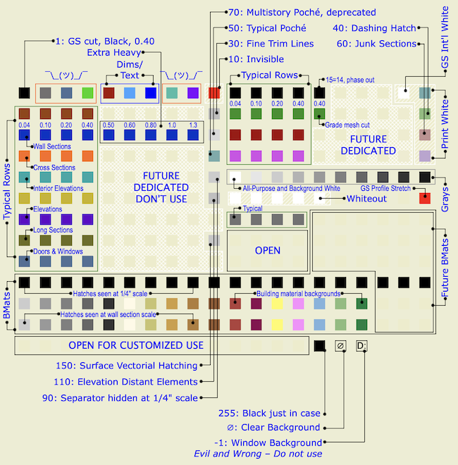
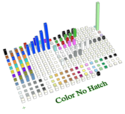
This object builds a model of any pen set in the project. Yes, a model. There is a block for each pen, which is the color of the pen, and the height of the block is the width of the pen enlarged from mm to meters.
There is no REQUEST for pen set data in GDL. So to get the pen set data, we need to export it to XML from Attribute Manager.
Then we run a series of regex find/replace operations in BBEdit, using an Automator application. This strips out all the XML formatting, leaving only the pen set data, and then adds some GDL code.
These are the regex operations:
- Strips tabs
- Replaces empty description tag with <Description></Description> for symmetry with non-empty descriptions
- Reformats width but I don't see the effect; must be for special cases
- Reformats each pen block into one line of #, width, RGB
- Replaces "1," at the beginning of each pen set with "PUT 1,"
- Deletes other attribute types
- Deletes header stuff before the first PenTable
- Converts PenTable tag to ID and name, code to put ID and name into arrays
- Puts pen #, width, RGB into PenData array, after pen 255
- Deletes all closing tags
As you can see, I can't remember why we need step 3, but I was afraid to remove it.
Just for fun, here is the search string for step 8:
<PenTable Idx=".*" Name=".*">\n<OdbObj Mv=".*" Sv=".*">\n<OdbRef>\n<guid>.*</guid>\n</OdbRef>\n<CreaTime>.*</CreaTime>\n<ModiTime>.*</ModiTime>\n</OdbObj>\n<Name>(.*)</Name>\n<Index>(\d*)</Index>\n<Flags/>\n<ModiTime>.*</ModiTime>\n<RegMemoTable MemoNumber=".*" Mv=".*" Sv=".*"/>\n<ReadOnly>.*</ReadOnly>\n<Pens>
These get replaced with this:
IDseed = IDseed + 1\rsetID = \2 \rsetIDs[IDseed] = setID\rsetNames[IDseed] = `\1`
The resulting text, which is bunch of PUT statements and arrays being filled, is copy/pasted into the Master Script of the template model object.
So now we have an object that knows the name of every pen set, and the weight and RGB of every pen in each one.
The names go into a VALUES{2} parameter list so the user can choose the pen set by name. I'm sorry they're not in alphabetical order; I could probably fix that.
The 3D script builds a matrix of blocks, each one with a custom material defined by the RGB of the pen.
The 2D is just a PROJECT2, making this, it just has to be, the most computationally intensive 2D pen table object anywhere.
You can graphically select the pen set using the slider marked with a plus sign at the bottom of the table.
Note: The object ignores the current model pen set. The colors and weights only come from the pasted data.
Requirements
Archicad 23 or 24
A Mac
BBEdit
Free Time
Instructions
In Attribute Manager, select all of the pen sets and copy them to the right by index. Export the XML attributes file. Drag the XML onto the Pen Data application icon. BBEdit will launch if it is not running, and the converted XML text will be presented in the front window, as well as copied to the clipboard.
Open the object and open its master script. Delete the sample text from between the two lines of asterisks. Paste the converted text here. Do a save as on the object. Place the object in the project. The pen set can be selected in settings, or by sliding the control at the bottom of the table.
Another idea: Graphically editing the weight of the pens via the height of the blocks, then rebuilding the XML file through crazy string operations, so we could import it back into Attribute Manager. This is not implemented at this time.
IFC is a format for exchanging models with data attached between different software. IFC elements are 3D construction elements and objects. IFC has nothing too with plans, annotation, or anything 2D.
The only consultant I have worked with is StructureCo, which is a pseudonym. The type of work is custom residential -- mostly wood members with some steel. This is our first try at this type of coordination.
My goals for the StructureCo collaboration:
• If I can get the beams labeled in the sections, and check that the structural elements fit, I can let them do the framing plans.
• Automatically label elements based on data provided within them, such as ID or profile.
• Let their layer names come through, with an extension.
• Bring in elements with proper classification.
• Avoid creation of attributes other than Complex Profiles.
• Let the consultant do the model 'their way' as much as possible. We try to be low-maintenance teammates.
In other words, let them do some of the work without sacrificing the consistency of our model and annotation process.
Adapted from my brief presentation at the DC Archicad User Group meeting earlier this month. If you want to look at the files, there is a download link at the end of the post.
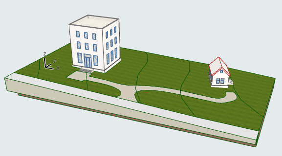
This is a simple scheme for using a single site model for multiple projects. It is applicable for everything from detached garages, to townhouse blocks, to proper campuses. The goals of this scheme are:
• Consistent 2D and 3D site data in each project, maintaining accurate story information.
• Visualization of the whole property in BIMx, while all buildings are easily kept up to date.
In our usage, the site is part of the main house's file. The site can be in a completely separate file using the same technique. The BIMx is published by the project file which contains the site. I will refer to the main house file and the small house file.
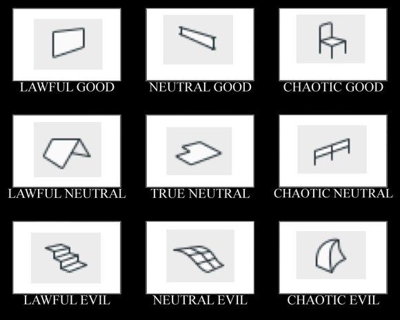
I didn't want to talk this to death. What I like about alignment charts is they are assertive rather than argumentative. You have to just look at them and work out the relationships among the things, and ask yourself if your impressions of the things agree with the author's.
I made this by instinct. The strongest notion I had was that the morph tool is chaotic evil. The second strongest notion was that the mesh tool is a relic and needs to be done over. Then I was on my way.
Having meditated on it a bit, I think this is what the axes mean:
The lawful-chaotic axis runs from standard orderly content to custom content. The good-evil axis runs from user flexibility to user frustration. With that, I will proceed to talk it to death with some comments on each item.
What shows:
• Walls
• Ceiling trim and finishes
• Ceiling fixtures including lights, fans, and mechanical fixtures
• Floor elements, including deck edges, stairs, counters
Using graphic override rules, floor elements are automatically shown dashed in RCP. And, ceiling elements, which are drawn dashed in the floor plan, are automatically shown solid. What a time to be alive.