On Land

Environment Information
At Rill Architects we run ArchiCAD on macOS. If you work at Rill, this is your stuff. If you don't, but you work in ArchiCAD, you may find something interesting. Anybody else, I don't know.
RSS
November 2006 Archive

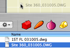
Drop the DWG in the floor plan window. It becomes a drawing. (Use inches for the units, unless it doesn't work, in which case you should use feet.)

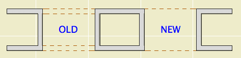
UPDATE: In Archicad 11 and above, you can drop the DWG into a worksheet window and then ghost the worksheet into the plan. (I still can't say 'trace', and notice again how much better 'ghost' is as a verb. 'Place as trace reference the worksheet into the plan.' Ugh.)

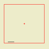
Trace the geometry you need. (See, 'trace' is already a word.) This is, at least:

• The property lines and setbacks
• The topographic contours (use splines)
• Streets and driveways
• Other critical features such as wells and septic fields
• Trees, if provided. Tip: Put the tree description (18" Oak) in the ID field of the tree object.
• North arrow, or at least a line showing the direction. (Needed to set north in the sun dialog.)

Watch your layers and linetypes. Note there are favorites for the contours and the boundary and setback lines.

I'm fairly confident the drop-trace method is best for our site plan needs. If you open the DWG, you need to manage the layers, the pens, and the objects created from blocks. It's a lot more fiddling, and then you need to trace the contours anyway.

Remember PDFs can be drawings too. If you have a PDF survey or plat, the principles are the same. BUT: Since PDFs don't have 'lines' in a CAD sense, you'll need to draw the boundaries and such using the given dimensions. Tracing PDF contours is probably OK.

When they mashed up PlotMaker with Archicad, they had to make views-in-layouts into proper elements, rather than flaky PM things. So we have the Drawing element, which can be edited as a polygon, assigned favorites, and given a marker, all of which makes the mashed up AC views-in-layouts much more pleasant than their ancestors.

But drawings aren't just for views; You can use them for PDFs. They're not just for layouts; you can place them in any model window.

DWG Drag
And finally, you can use them to place DWGs. Rather than opening or XREFing the DWG, you can drag and drop it from the Finder directly into a model window, where it becomes a drawing. If you just need a DWG for tracing or reference, this is the way.

When you drop the drawing, the only question you have to answer concerns the units. Use 1 inch. If the drawing is 12 times too small (I think that's how it works), drop it again and choose 1 foot.

A few other points:

• A big advantage of the drawing method is there's no layer contamination.

• Drawings placed in this way can be updated, just like view drawings, and will appear in the drawing manager.

• The drawing will come in with the default settings of the drawing tool (though there will be no title). As for the pen set, use '*Layout', which is overwhelmingly black and works for most DWGs.

• If you're placing DWGs for use in output, more pen management is likely in order, which is another topic.

• Tip: Put the drawing on a remote story and set that story to ghost. Now you can work normally without accidentally selecting the DWG.

Two parameters added to the 'Plan' options in the Interior JAM9 door, so you can turn off either side of a cased opening. The parameters are 'Cased Op Line (Swing)' and 'Cased Op Line (Opp)'. Both are on by default. (Note: You will only see them in the parameter list, not the interface pages.)

This feature address this condition, where openings in each of two walls are supposed to look like one thick opening:

Cased Opening Lines

Swing = the clicked side when the door was placed. Yes, it can be tricky to tell which is the swing side of a cased opening, but there's nothing else to call it. If one switch doesn't do what you want, try the other one.

I'll probably add this feature to all the threshold lines when I next update the doors, which will be after the transition to 10 is complete.

bearglacier2.png

I've started adding tags to the posts in here. Tags are 'keywords' which provide another method of organizing related info. They're nice because you can use gobs of them where so many categories would be cumbersome. For example, a category for 'trim' would be silly, but a trim tag is useful. And the detail tag can point to info on drawing details, detail sheets, or the detail tool.

You can see all the tags in use at the bottom of the index page (or click here), and in the sidebar of most of the other pages. In this arrangement, more common tags are shown larger. That model tag is huge.

Tags for each post are shown at the bottom of the post.

When you click on a tag, you get a search results page of all the entries with that tag.

Grid Cell
Location: 1 General / Title & Layout

(Again, pardon the 'a'. Some things can't be fixed in place.)

This object represents the available area of a detail sheet grid cell, or group of cells. Use it in your details to plan how the detail will lie in the cell. Very similar to Sheet Area RND10, which is used for plans.

More»

The MacBook Pro finally came. I knew it would be much faster than the 1.67Ghz G4 it is replacing. Well, I thought I knew.

Far be it from me to actually try benchmarking that anyone else could use. It's all relative anyway, so let's look at the relatives:

I timed an update of a 3D perspective view placed in a layout. (Who knew views would be so helpful for benchmarking? None of this setting and fiddling business, because all the settings are in the view. Very convenient.) The model is pretty hairy and the fills are on.

First, I would normally only update this drawing on the PowerMac G5. That's a quad 2.5Ghz, 3GB RAM. The update takes a way tolerable 2:28.

The old PowerBook. (Not that old. 16 months. The last, best PB.) 1.5GB RAM. I know full well that a G4 is not up to the task, especially in 10. Not that you can't work; you just need to be tactical. Always marquee the 3D window. Turn all the fills off. Refrain from generating full building sections. Things like that. It takes a different mindset, but you can still be productive.

I would never generate such a view on the PB unless absolutely necessary. I'm fairly sure I never updated this particular drawing on that machine. Still, I was quite surprised at the result, a truly pitiful 6:26. (Moment of silence.)

Yeah, I need a new computer. That's why I bought one. This is the 2.33Ghz Core2 Duo, 2GB RAM.

First I tried the PPC Archicad 10, which runs under the Rosetta emulation layer. As with any emulation, expect a performance cost. (In real life, I'll need to run 10 in this way for a while, because the Universal Wibu driver breaks AC9. I don't use 9, but I need to maintain libraries in it.) The 'wrong' AC10 updates the drawing in 2:08.

So this here portable is more than 10% faster than my 1-year-old G5. In emulation.

Swap out the Wibu driver and really go for it. In the properly-compiled AC10, 1:06. Twice as fast as the G5, almost six times as fast as the G4 PowerBook. Holy @#$%.

Pergola Roof Plan
Original here.

Turn on the Cover Fill to make the pieces opaque (White, pen 91). Useful for roof plans of a pergola. Stories below will not show the fill.

Eave Length
Original here.

I Added an 'Eave Length' parameter to the plan options. This allows you to show a straight eave before the curve begins:

I also made the plan fill a cover fill, so it will respect the display/model view options.

Other dialogs here.

The source files of some Hotlinked Modules are missing

Sources of the following Drawings are unavailable!

If this item is part of a clone, its clone will also be deleted

Polygon boundary intersects itself!

More»

bearglacier1.png