On Land

Environment Information
At Rill Architects we run ArchiCAD on macOS. If you work at Rill, this is your stuff. If you don't, but you work in ArchiCAD, you may find something interesting. Anybody else, I don't know.
RSS
June 2007 Archive

What? I know how to open a file! Jeez!

OK. Just in case:

Always open AC files via right click -> Open With or by dragging the file to requisite AC icon on the dock. I do the dock thing; I'm just not a context menu person usually.

Most important, don't double-click PLNs. Double-clicking will only give consistent, predictable results if you have exactly one copy of AC on your machine.

When you install a new version of AC, as you soon will in the form of 11, that version becomes the default application for opening PLNs. So you double-click your AC10 project, it opens in 11, you don't notice the difference because there isn't much, you save it, and next time you try to open it in 10 it doesn't work. (Yes, backsave. Real convenient.)

Always keep current versions of AC on the dock. Even if you use the right-click method, the dock gives you visual confirmation that the right application is being used.

Graphisoft gives poor support in this area, by making the icons identical and naming each version, precisely, "Archicad".

Double-clicking files is one of those 'automatic' things that's great if you can trust it, but when it's not predictable it makes trouble. It's not just AC either, recently my .docs started opening in Pages for some reason.

What about that 'Change All' under Open With in the Get Info window? That fixed my .doc issue, but it doesn't reliably assign the right 'Archicad' version.

So, right-click or dock. If you have a bad habit here, change it now before 11 starts getting on your nerves.

Update re app icons: Mr. Briggs to the rescue.

11 Icon

Gray Top View
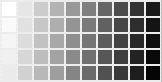
This is a non-destructive method for creating a grayscale, shaded, top view of a model, for placement in a site plan. It uses a second project file with redefined material colors. In order for this to work you need a range of grayscale pens. The more pens in this range, the richer the image. In our templates we have fifty.

Steps:

1. Make a new project. Use settings of latest project, launch new instance of AC.

2. Set up the stories to match the main project. For some reason the 'latest project' settings don't include this.

3. Save with a name like '[Project] for roof plan.PLN'. Put it in 1 Design / Modules.

4. Hotlink the model's project file into the new project.

5. Set up the 3D window with top view, internal engine, shaded. Turn off the undesired layers. There's a layer combination 'x Shoot Roof Plan'; that's a good place to start. Most of the visible elements will be on A Roof2, A Deck2, A Fireplace, etc.

6. And, most of the visible polygons will be of a handful of materials. Determine which materials these are.

7. In Attributes -> Materials, redefine all these materials to the same gray color. (Try 75%.) You only need to change the main material color.

If you don't see the color changes right away, try updating the hotlink. As you gray-ify materials, you might see more that need to be done.

The trick here is that there's no damage to the materials in the main project.

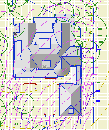
There's your gray model. I can think of at least three ways to get it back in the main project.

• Save a 3D view of the gray model, and place that view as an external drawing on top of the site plan. Pro: It's direct. Con: Tricky to line up with site plan drawing. External updates increase overhead, and at the moment they're buggy in 11.

• In the gray project, copy and paste from the 3D window to a detail window. Save a view from there and place as an external drawing on top of the site plan. Pros: You can edit the 2D image to erase elements or change line weights. The 2D drawing is more detectable and easier to line up with the site plan. External updates of 2D views run faster and more reliably. Con: Copy, paste, and subsequent editing needs to be done over if the model changes.

Grayscale Pens
(Note: Shaded fills in the 3D window can use the full range of RGB. When you paste into a 2D window, you get solid fills of the pen color closest to the color in 3D. So the more grays you have available, the more variation you get in the image.)

• Copy and paste to a detail window as above, then save a module of the lines and fills. Hotlink the module into the site plan in the model environment, using a site annotation layer to control visibility. Pro: Visible in model environment, no second drawing to align in the layout. Updating hotlinks does not need a second session of AC, so it's faster. Con: Copy, paste, and subsequent editing needs to be done over if the model changes.

All three methods require that you open the gray project in order to modify the content. There's no way for the gray project to know the model has been modified and the hotlink needs to be updated.

I'm using the third one. A 3D external drawing is a big chunk of overhead. Both view solutions require an additional drawing in the layout, and the shaded content isn't visible in the model environment. Editing the lines and fills is an extra step, but it also looks better.The external 2D drawing and the hotlink give the same graphical result, but the hotlink update is faster.

If you ever need to update the image for changes in the model, all you need to do is:

• Save the main project, open the gray project, and update the hotlink.

• Re-copy and paste to the detail window. Mess with the lines again as needed.

• Select, copy, save as module from clipboard, write over the existing one.

• Back in the main project, update hotlinks.

Sheet A3-3
The distinctive feature of the detail sheet is the grid. The grid encourages us to think about how details align, and forces us to be economical with the space we have for annotaions. And it looks better, and it's standard practice.

The grid deployment has two parts: The Grid Cell object, and the 'Detail' master layouts.

You should always develop details with the Grid Cell object. Place it before doing any annotations, so you can use it to align the notes. Most details should need only one grid cell. For larger details, stretch the object to an adequate extent. Much more on how the grid is laid out can be found at the Grid Cell documentation link above.

The Grid Cell object doesn't draw the grid itself. That is handled automatically by the Detail masters. The master also takes care of numbering the drawings by their position on the sheet, and it automatically eliminates lines that would cross a multi-cell drawing. Grid setup can be found in the master's settings.

There are three detail masters in the templates, one for each sheet size. The number of available cells depends on the size.

Detail drawings use automatic titles. There is a guideline within the Grid Cell object to help with placement of the title.

Wall sections need not be placed on a detail grid, although you can place a wall section on a detail sheet if you have space and there aren't many wall sections.

The standard project folder setup. The screenshots are out of date, but the descriptions are current as of Archicad 21.

More»

Summary: With the model and the layouts in one file, pen sets manage the difference between the model pens and the output pens. In addition, they can do view-option-type tricks.

Background: In Archicad 9, there was one set of pens. In PlotMaker 9, there was also only one, and it could be different from the set in AC. Or, each drawing could have its own pens, but it was impractical.

Our standard has always been to use a colorful set of pens for modeling, which translates into a black/white/gray set of pens in layouts. We are far from unique in this arrangement.

In 10, they threw PM into the abyss, so they needed a method to maintain at least those two groups of pens within the new unified project file. So, Pen Sets.

More»

Note: This post has been updated for AC18.

Current naming standards. Still very boring.

These rules aren't set in stone, but if we all stay near the rules we all stay near each other. Like all standards, they work most of the time. When a situation is addressed by the standards, you can save your creativity for the projects.

More»

Location: 06 Wood & Plastic/Trim & Moulding

New version of the main moulding object.

Listen, you will have dozens or hundreds of Crown Tool elements in a project. The object is designed to be used all the time. I.e., it does a lot. Get familiar with what it can do. If it doesn't do something you need, speak up!

This version: There are additional 'shapes' and more parts available. New shapes:

• "J"; like "U" with an independent length for the third segment.

• Rakes, including curved rakes.

• Arch.

New parts:

• Wall Backer 2. Placed behind the Wall Backer.

• Crown Cap. Placed below the crown.

• Soffit. Flat piece placed above the ceiling backer. You will often need this to help the rakes cut the roof edges.

I regret to inform you that I can't continue support the custom interface panel at this time, so we're stuck with the parameter list. Essentially, all this stuff is hard enough to simply get working, and the user interface development tech is painfully disrespectful to time constraints. I have to choose between features and interface and it isn't a hard choice. If this makes you unhappy reread the new features list above and cheer up!

Full documentation below the fold.

More»

Location: 12 Furnishings / Casework

Another tweak to the blob. You can turn the Front Panel off. Why? So you can build the front of the cabinet out of a wall, and place the doors using 12 Furnishings / Casework / Cab Door Door JAM81. You would place that with the door tool, yes. (There's also Cab Door Object JAM81, the object tool implementation of the same thing.)

While I was in there I added a parameter for the box Stock Thickness. It defaults to 3/4". So the wall thickness should be 3/4" unless you change that parameter.

In plan, the front line is drawn at the front of the front, whether the object's panel is on or off. Tip: Use the front line as a guide to draw the wall.

Cabinet Axon
I know, I forgot the handles, sorry

# Milage...

Car
4 months, 1 oil change, 3773 miles, 71.43 gallons, 52.8 mpg (4.45 l/100km). Cost savings to date compared to previous car which got 24-25 mpg and needed premium: $281.

-James 2007-06-19-1612

This is a simple method for calculating gross floor area of a project, using the element schedule feature of AC10. It also gives us an introduction to basic element schedule technique.

The method assumes a tolerance for approximation; you need something to say when they ask, how big is it. If you need precision, you can figure it out I'm sure.

This schedule is provided in the templates, and it can be imported from 3 Resources/AC/Element Schedules. Or you could build it from scratch quite easily.

More»

An object like the Foundation Drain is trying to offer total geometry and annotation for a particular detail. We want to pack this object with all the data we can think of. The geometry is in good shape, but we're missing the notes calling out all the parts. These will need to be added manually with labels or texts. Since these notes are standardized, they will be written down somewhere; if nowhere else, in the last place you drew the detail. Or in a module, or in a text file. Either way, it's remembering and typing or copy and paste.

How could the notes live in the object? You could script a series of 'labels', with leaders pointing to the detail parts, and editing hotspots to position the texts. I'm skeptical of this. It's sophisticated coding to get an interaction that, to the user, would never be as smooth as moving text elements and drawing arcs and labels. To me, placing the notes isn't the problem, it's remembering/locating the data to write into them.

Here's another idea that would let us keep the notes in the object. Create a switch in the settings to put the whole thing in 'note mode'. Instead of drawing the lines and fills, the object creates a series of text blocks. (These can be multi-line and arbitrarily styled, like text elements, using the TEXTBLOCK and RICHTEXT2 commands.) Then you could copy/explode the object, which would give you text elements you could stretch and arrange as needed.

Unfortunately it doesn't work. When a multi-line text object is exploded, you get multiple single-line text elements. Not helpful.

We need RICHTEXT2 that explodes into a single text element regardless of shape.

Shrimp Trawlers