On Land

Environment Information
At Rill Architects we run Archicad on macOS. If you work at Rill, this is your stuff. If you don't, but you work in Archicad, you may find something interesting. Anybody else, I don't know.
RSS
Sheet Index

Sheet T1
Things on the cover sheet and where they come from.

First of all, the cover sheets have their own master layouts, C Cover, D Cover, and E Cover. The 'data zone' at the bottom of the sheet is proportioned differently for each sheet. This way, if you need to change the sheet size, you just change the master and you don't have to worry about resizing the legends and whatnot.

Because the cover sheets are all customized, a lot of the information rests on the cover master rather than in the cover sheet layout itself. Throughout, I'll refer to the 'master' and the 'layout'.

More»

Sheet A1-1
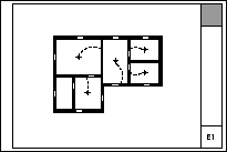
• What Shows. Full height walls. Counters, appliances, and plumbing fixtures. Stairs, decks, driveways, floor finish fills. Stair and deck railings. Most roofs. Overhead elements including beams, ceiling lines, and roof overhangs. Room names, preferably in the form of zone stamps. Dimensions. Centerline markers. Names of cabinetry elements ('Bench'). Floor elevations. Markers for sections, elevations, interior elevations, plan enlargements, wall sections, and details. Door and window tags.

• Wall Cleanup.
Plan layer combinations should have different intersection codes for plan and 3D walls. (E.g., A Wall Ext has '1', A Wall3 has '2'.) This eliminates gaps where visible and invisible walls meet.

Wall cleanup has improved greatly over the years, but can still be tricky for complex intersections. Use a patch if you must.

• Display Order.
(Front, back, etc.) Use display order to to make overlapping elements stack correctly. In order for elements to mask elements behind them, they need a fill with a background pen. If you don't want a fill pattern, use 'Empty Fill'.

Generally, annotations should be all the way in front so they aren't obscured by anything. Walls should in front of everything except annotations. Beyond that, you have to pay attention. Counters in front of floor fills, soffit lines in front of counters, stair railings in front of treads, etc.

• Pens.
More on pens here. Walls are 5-weight (usually 15). Edges (Counters, stairs) are 2-weight. Dashed overhead elements are 2-weight. Appliances, plumbing fixtures, and other such objects are 2-weight. Floor finishes are 150. The background pen of construction elements is 50, and existing construction elements are overridden by pen 91.

A note on composites: Contour, separator, and background pens should set correctly in the composites. Walls in plan should be set to use the composites' pens. Stud wall composites should have the separator lines hidden; that is a composite setting, not a wall setting.

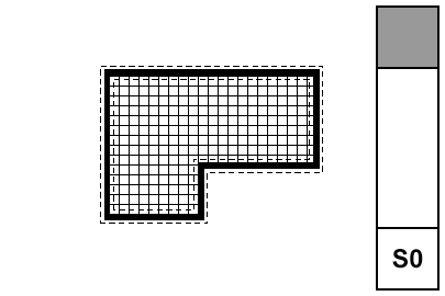
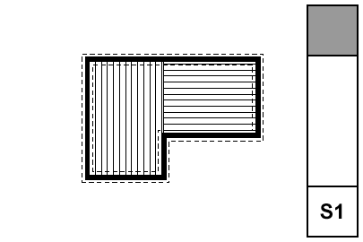
• Floor Finishes. Either: 1) Fills on F Floor Fin2. 2) Slabs with a cover fill on F Floor Fin2. 3) Cover fills on the zones. In practice #1 is most common.

• Dimensions. Here. For small rooms, consider enlarged plans and put the dimensions there.

Sheet A1-4
• What Shows.

Roofs on the A Roof2 layers. Gutters (on F Gutter). Top elements of chimneys on A Fireplace or A Roof2. Notes on +A Arch Note Reg Scale. +A Misc Line. The roof plan uses the same layer combination for output as the rest of the plans, A1 Floor+Roof Plan.

Roof elements will be placed on the lowest story on which they should be visible, and they need to show enough stories above to be visible on the roof story. For some roofs this means 'one story up', and for some it means 'all stories above' (custom setting). Much more on roofs in plan here.

• Annotations.

For the slope arrow, use a line with an arrowhead at one end. The arrow points down.

Note the roof materials, gutters, crickets, etc.

Sheet A2-1
Everything I can think of about sections and elevations.

More»

Sheet A3-1
These are two detail-oriented drawing types that don't exactly go together, but they usually fit on one sheet. If there are too many assemblies or the schedules are very large, they can be separated.

More»

Sheet A3-2
The big difference between a building section and a wall section, besides the scale itself, is that the wall section has much more fine detail.

The additional detail of a wall section comes from (some) scale-sensitive model elements, along with 2D geometry and annotation placed in/around the modeled section. That's right, drawing. But this kind of drawing doesn't leave the model behind, and the section window remains live. In section, your modeling goal is an accurate 'envelope' of empty poché that looks clean at 1/4" scale, and can accommodate fine detail and annotation at wall section scale.

More»

Sheet A3-3
The distinctive feature of the detail sheet is the grid. The grid encourages us to think about how details align, and forces us to be economical with the space we have for annotaions. And it looks better, and it's standard practice.

The grid deployment has two parts: The Grid Cell object, and the 'Detail' master layouts.

You should always develop details with the Grid Cell object. Place it before doing any annotations, so you can use it to align the notes. Most details should need only one grid cell. For larger details, stretch the object to an adequate extent. Much more on how the grid is laid out can be found at the Grid Cell documentation link above.

The Grid Cell object doesn't draw the grid itself. That is handled automatically by the Detail masters. The master also takes care of numbering the drawings by their position on the sheet, and it automatically eliminates lines that would cross a multi-cell drawing. Grid setup can be found in the master's settings.

There are three detail masters in the templates, one for each sheet size. The number of available cells depends on the size.

Detail drawings use automatic titles. There is a guideline within the Grid Cell object to help with placement of the title.

Wall sections need not be placed on a detail grid, although you can place a wall section on a detail sheet if you have space and there aren't many wall sections.

Sheet A4-1
With the advent of graphic overrides, reflected ceiling plans are no longer a wilderness of tracing and weird hacks.

What shows:
• Walls
• Ceiling trim and finishes
• Ceiling fixtures including lights, fans, and mechanical fixtures
• Floor elements, including deck edges, stairs, counters

Using graphic override rules, floor elements are automatically shown dashed in RCP. And, ceiling elements, which are drawn dashed in the floor plan, are automatically shown solid. What a time to be alive.

More»

Sheet T1

Most of the advice about sections and elevations applies to interior elevations as well. We do interior elevations because the larger scale lets us show more information. Some of this information is already in the model and the scale change reveals it. Some of it is fine modeling that doesn't need to be done until you start the interiors. Some is very fine detail that is done in 2D within IE windows.

Use the interior elevation tool. It's fussy but it works. I recommend always using the polygon method, never the single line method. There are two reasons for this. First, often you think you only need to elevate one wall of a room, but later you need another wall. Second, polygon IEs are easier to select because you can grab them by the marker.

More»

Sheet E1
What shows: Walls, stairs, counters, decks, appliances and mechanical equipment, and all electrical symbols.

More»

Sheet S0
The foundation plan shows the foundation walls, footings, slabs, and related annotations. Everything that touches the ground. It can be combined with the first floor framing, but an independent foundation plan can give more information with less clutter. The layers, layer combination, and views required are included in the templates.

• What Shows.

• All plan walls, A Wall Ext, A Wall Int, S Wall2.

• Steel columns which rest on footings, S Col Steel. Other columns remain on S Column.

• All footings, S Footing.

Framing plan layers which should be hidden in foundation plans: S Beam, S Framing, S Column, +S Struct Note.

• Annotations.

• Foundation dimensions. It should be possible to use the foundation plan to stake the project. When using a foundation plan, you should only have architectural (interior) dimensions on the A1 basement plan.

• Wall and footing sizes.

• Dimensions to all columns.

• Graphics and notes describing all slabs and their reinforcement. Elevations of slabs to project zero. Use fills to show reinforcement. Use a background of pen 91 on text blocks to make them legible when placed on fills.

• Detail markers calling out wall types and other relevant details.

Annotations belong on +S Foundation Note. Annotations which also show in the framing plans belong on +S Note All.

The foundation plan is typically generated from the same story as the first floor framing, so it requires a separate layer combination, S0 Foundation Plan. The display option combination, S Foundation, differs from that of the structure plans only in that the cut fills are Vectorial Hatching instead of Separators only.

The foundation plan's sheet number should be S0 (zero).

Sheet S1
Rules for framing plans. Foundation plans are slightly different. Roof framing plans are very similar. I'll have a separate note for them. I wonder what the difference between 'slightly different' and 'very similar' is.

• Walls. Display of walls is controlled by Display Options. The 'Cut Fills' option should be set to 'Separators Only'. The walls will be clear, with lines at the separators; for example, between concrete and stone. Use the 'S' Display Option Combination.

• Bearing Walls. To show a bearing wall, draw a fill on top of it. This is a non-associated, additional element. Use the fill '*Masonry Block', with a background pen of 50. Use the layer +S Struct Note. So: Walls are clear, except bearing walls, which are shaded.

• Rafters & Joists. Fill elements of the fill 'Joists 16OC' or 'Joists 12OC'. If you need other spacings, you need to make more fills. The fills go on the layer S Framing, which only shows in the framing plans. Rafter and joist placement is diagrammatic.

• Rafter & Joist Labels. Object 'Joist Note JAM9'. With the joists shown as fills, you don't need to show the extent in the note object, although it has that option.

• Beams. Beams should generally be modeled and labeled in sections. Use the objects Wood Beam JM9 and Steel W Shape Beam JAM9, etc. Most beams should be on the layer S Beam, which shows in section. If the beam is just used as a note, place it on S Framing.

Beams can reference their calculations by use of the ID tag in the objects.

• Annotations. All annotations should go on the layer +S Struct Note, unless you want an annotation to show in the foundation plan simultaneously. In that case, use +S Note All. Use a background of pen 91 on text blocks to make them readable when placed on fills.

• Structure Notes. Loads, criteria, etc. are part of the General Notes PDF. Specific notes can be added to the plans using text blocks.

Sheet S3

Everything in the general framing plan discussion also applies to roof framing plans. There's a few special considerations:

• The roof framing plan should usually be generated from the top occupied story, not the roof story. For most projects, this is either the attic or the second floor. In the past, we have used the roof story, but not any more. It is very beneficial to show walls in the roof framing; in fact, we should show walls from multiple stories where applicable. By using an occupied story for the plan, it's one less story to be shown using the trick linked above.

• Show the outlines of the roofs. It is not feasible to show the roofs themselves, you must trace them or copy and paste from the 3D window in the classic style.

If you are showing the actual roofs in your architectural roof plan, put the traced/pasted roof lines on the +S Struct Note layer. If you are using the cut and paste method for the architectural roof plan, you can use the same lines for roof framing.

If you have dedicated structure roof lines (not reused in architectural), change the hips and valleys to a dashed linetype.

To put it another way.

Option 1 (preferred): Use roof elements on A Roof2 for the architectural roof plan. Use copied lines for the roof framing, on +S Struct Note. Switch the hip and valley lines to dashed.

Option 2: Use copied lines for the architectural roof plan, on +A Roof Plan Line. The same lines show in the roof framing. You can't do the dashed line thing.

• If hip and valley framing members are modeled, they require special attention to place them right. It's often OK to show these members as 2D only. There are two ways to do this: 1) The wood beam object has an option to turn the 3D off. 2) Put the beams on the S Framing layer, which is hidden in section.