Converting 2D elements for use in 3D.
Any 3D element(s) can be saved as an object with the Save Project As... menu command. (In Archicad 11, Save 3D Model As...) This technique is known as 'slabifying' since such models are often built from slabs. Objects saved in this way are dumb (not parametric), but it's still a useful trick.
2D elements can't be saved this way, because they never appear in the 3D window, where 3D object saving takes place. Despite the fact that GDL contains commands for 'flat' shapes in 3D, including LIN_ (a line) and PLANE (not a joinery implement). But there is a workaround for 'slabifying lines'. When you open a 2D DWG as an object, 2D lines are created as LIN_ statements in the 3D script. When you place the object in the model, you get the 2D geometry in 3D.
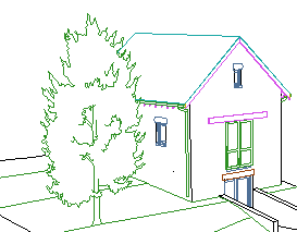
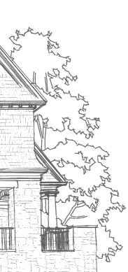
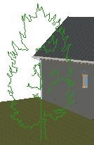
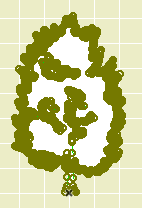
It's that simple at it's simplest, but real world applications need some tweaking. In this example, I'm converting an Archicad library 2D tree elevation symbol so I can use it in a sketch render image. Other applications might be a complex ornament in a hidden line elevation, or a busy glazing design placed in front of a conventional window.
Do a Save As in DWG format. I use the same translator we use for most export cases.
Open that DWG using the Open Object command on the File -> Libraries and Objects menu. The resulting object is untitled and consists of:
• The original 2D geometry in the 2D symbol window.
• Some error checking code in the 2D script, along with a FRAGMENT2 command to draw the content of the 2D symbol window.
• A bunch of TR3D parameters in the main window, which I don't understand.
(More on the GDL environment and the various windows here.)
These are the basic modifications to the object:
• Delete the TR3D parameters.
• Delete the top of the 3D script; everything before the first LIN_ statement. The last junk line is probably a PEN directive like 'PEN 10'.
• Above the first LIN_ statement, add the code 'ROTx 90'. This rotates the geometry up from horizontal to vertical.
• Delete the entire 2D script.
We can find several things to fix.
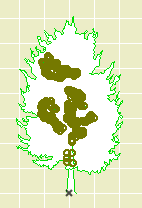
The default behavior of DWG objects is to show the same geometry in the 2D symbol and the 3D model. We flipped the 3D lines to vertical, but the plan symbol is still lying flat.
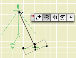
This cross symbol is done with some very simple code in the 2D script. The long line represents the width of the tree geometry, and the short perpendicular lines let me rotate the object precisely toward the camera.
Here's the code:
!! Nodes along main line

HOTSPOT2 0, 0

HOTSPOT2 A/2, 0

HOTSPOT2 -A/2, 0

!! Lines of cross

LINE2 -A/2, 0, A/2, 0

LINE2 0, A/8, 0, -A/8

!! Nodes of perpendicular line

HOTSPOT2 0, -A/8

HOTSPOT2 0, A/8
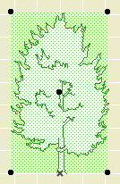
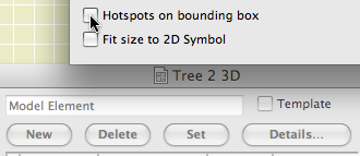
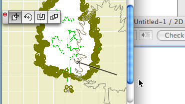
I also want to turn off the 'four corners' nodes in the plan symbol. These are the default nodes in case there are no HOTSPOT2 statements in the 2D script. To turn them off, click the 'Details' button at the top of the main object editing window, and uncheck 'Hotspots on bounding box':
If I did want to see a real tree symbol in the plan, I would have the 3D flat tree object 'call' the regular 2D tree symbol object. That's not too tricky, but it is out of scope at the moment.
When the DWG was opened as an object, the line geometry was created at the same size as the original symbol. We can add some simple code to make the tree stretchy while maintaining its proportions.
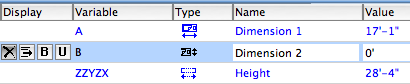
First we need to make sure the default dimensions of the new 3D object reflect the actual dimensions of the geometry, which will be the same as the dimensions of the original symbol object. This tree has a width of 17'-1"; that value goes in the A parameter. The height is 28'-4"; that value goes in the ZZYZX parameter. The B parameter is not used and can be hidden using its 'X' button.
This 3D script code lets a change in the height of the tree force a proportional change in the width. The MUL statements find the ratio of the new height to the default height, and shrink or enlarge the height and width accordingly:
ROTx 90 !!flip up to vertical
MULx ZZYZX/28.33' !!adjust width
MULy ZZYZX/28.33' !!adjust height
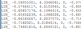
LIN_ -0.59055301, 6.3346061, ....
This is the quick/dirty approach. The width of the object will change, but you won't see that reflected in the width parameter.
This code will keep the two dimensions in proportion when either one is changed. This goes in the Master Script:
IF GLOB_MODPAR_NAME='A' THEN !!when width changes do this

ZZYZX=ZZYZX*(A/17.083') !!adjust height proportional with new width

PARAMETERS ZZYZX=ZZYZX !!update height parameter in settings

ENDIF !!done

IF GLOB_MODPAR_NAME='ZZYZX' THEN !!when height changes do this

A=A*(ZZYZX/28.33') !!adjust width proportional with new height

PARAMETERS A=A !!update width parameter in settings

ENDIF !!done
The 3D code is the same as above.
With this code you can stretch the object in plan or 3D, or edit the size in the settings, and the object should keep its proportion.
What if we wanted to stretch the height and width independently? In this case, get rid of that Master Script code and change the 3D code to this:
ROTx 90 !!flip up to vertical

MULx A/17.083' !!adjust width

MULy ZZYZX/28.33' !!adjust height

LIN_ -0.59055301, 6.3346061, ....
The tree object itself can contains a fill (user-hostile screen background color by default), but the automatic DWG object doesn't convert it, so the new 3D object is transparent. We want a paper doll tree that can mask elements beyond.
The solution is to add a PLANE statement to the 3D script in the shape of the tree object's fill. It's a bit more work. We will drag-and-drop the fill to make the PLANE and outline, while using the DWG method for the interior lines.
3. Drag-and-drop the fill to get the PLANE geometry:
• Create a new object. (File -> Libraries and Objects -> New Object) Open the 2D script window. Arrange the windows so the drawing window and the 2D script are both visible. Use the arrow tool to drag the fill element to the 2D script window:
This will result in a (very lengthy, again) POLY2_B{3} statement:
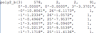
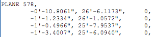
• Both POLY2 and PLANE (among many others) use a list of coordinate locations to draw a polygon. We can use a find-and-replace trick to turn POLY2 coordinates into PLANE coordinates. In the auto-generated code, the coordinates begin on the third line. Do a Find and Replace (on the Edit menu), replacing " 1," with " 0," (That's three spaces at the beginning of each.) You should see the change on each coordinate line. Copy all the coordinate lines to the clipboard. (Cmd+C) Also, make note of the number on the first line, right after the POLY2_B{3}.
• Open the DWG object with the interior lines. In the 3D script, following all the LIN_ stuff, type 'PLANE', then a space, then the number from the POLY2_B{3}, then a comma. Hit return, then Paste in the coordinate code:
The PLANE draws the opaque polygon and the outline, while the LIN_ code draws the interior lines.