On Land

Environment Information
At Rill Architects we run ArchiCAD on macOS. If you work at Rill, this is your stuff. If you don't, but you work in ArchiCAD, you may find something interesting. Anybody else, I don't know.
RSS
July 2005 Archive

All Entries | 1 | 2 | 3

Location: Doesn't matter; window & door markers are selected from the flyout in the info box or the 'dimension marker' tab of the settings dialog.

WindowTag: When the ID doesn't fit in the regular hexagon, the shape elongates to accommodate it.


DoorTag: I fixed that upside-down text thing, I'm pretty sure. I took out the Flip Text parameter. If it gives you any trouble let me know.

2005-07-29.jpg

Update. The AC11 versions have RCP-awareness.

Location: 13 Special Construction

Two objects (primarily) for cutting coved recesses into ceilings, using solid element operations. One's a circle, one's a rectangle. Guess which is which. The parameters of each are similar.

The fillet radius must be less than or equal to the height. The resolution of the fillet is controlled by the Fillet Facets parameter. For the disc, the Resol parameter controls the resolution of the circle.

You can turn the objects upside-down with Flip Z. I can't imagine many cases for doing so, but you never know.

In practice, your ceiling slab will be the target, and the object will be the operator.


Location: 06 Wood & Plastic/Trim & Moulding

Exactly like the other recent panel objects. This one is a parallelogram suitable for going along stairs. It's a window, and should be used with a thin wall.


The height is the height of the vertical sides, not the overall height.

The slope can be set either by entering the angle or the rise and run. Note: Stair Stringer JAM8 knows its angle in degrees. You can copy it from the settings and paste it into the panel's settings.

It's one of those things that's easier to edit in a section window. Remember windows and doors can be stretched and copied in section.

It looks slightly different in plan from Trim Panel JM9. The handle lines point in the downward-sloping direction.

This isn't a new layer so much as a fork of the old A Roof layer.

In AC9, as everyone knows, model polygons can have a cover fill. This means generally much less drawing, and more showing of those model elements in plan. It also gives the opportunity to 'stack' model elements in plan using Display Order (Send forward/back.)

In AC8.1 and earlier, you might have placed a counter slab on a A Cabs3, and a fill on A Cabs2, now you can have just the slab on A Cabs2. This promotes unity.

This ability, of course, extends to roof elements. It is possible, with some work, to show a roof plan built from actual roofs. This technique will have its own post.

Where we used to have one layer for roofs, because they were all 3D-only, now we have two, so we can choose to show roofs in plan, or not. We maintain the pattern of other 2D/3D layer pairs: Deck2/Deck3, Cabs2/Cabs3, Stair2/Stair3, etc.

The layer +Z Room Name is no longer with us. Dust to dust. Polvo a polvo. Room name objects in plan should go on the layer +Z Zones. This is the layer for zones of rooms. If you use zones, the stamp becomes the room name. If you don't, you can still use that layer for the object.

In passing, I will encourage you again to use zones.

Room names in section still go on +A Arch Note Reg Scale.

(This is for AC9. 10 is here.)

What happens when the existing drawings are done.

The basic idea is to keep the existing conditions, both the PLN and the layout book, tucked away safely. It is theoretically possible to get existing drawings out of the addition project, but it's more trouble than it's worth.

More»

I will use a new home in this description. Existing drawings are very similar. Warning: This is a whopper.

More»

(So Jon says, where's the existing template, and I tell him, and he says I looked online and I didn't see that, and I said, well I'll fix it, so here ya go. The library names were wrong too!)

1. Duplicate the zTemplate folder and rename it with the project name. To duplicate a folder, drag and drop it within the same window while holding down the Option key. Use the client name. If this is a second, or later, project, add a number. (Please don't use roman numerals, they are hard to read.) If it's a sub-project or related project, add a descriptive term. Examples: Stevens. Kernan3. Salamander Garage.

2. Open the project file template for new home or addition. The template names end in .tpl. The new template is at the top of the project folder. The existing template is in the '4 Site & Existing Conditions' folder.

3. In the library manager, make sure you have 'Archicad Library 9.pla', '1 Rill & Decker LIB9', and '2 Project LIB9' loaded. Click 'Library Cache Settings' and make sure 'Use a Local Copy' is UNchecked. Click 'OK' and 'Done'.

4. Once the libraries load, Save As. Format: Archicad Project File. For the name use the client name, similar to the folder name. For an existing house use 'Existing Somebody.PLN'.

5. Go to the Finder and delete the project templates from your project folder. They are no longer needed. If by some weird chance you need a template again, you can always get it from the zTemplate folder.

6. Get busy!

Alphabetical by name of thing. Please suggest improvements and additions. Note: I change the date whenever I update this, so it will pop up every now and then. Rest assured it's not all new. Big changes will have a post of their own.

Changes in this update: S Wall layers, the fireplace stuff, A Roof2 (roofs in plan), CenterLine & CenterPoint objects, gross area calculation, room name object moves to A Zones.

More»

Location: 06 Wood & Plastic/Trim & Moulding

Identical to Trim Panel JM9 and Trim Panel Ceiling JM9, except it's a skylight. And since it's a skylight, it can only be rectangular.

(Q: Why don't you give the ceiling version a slope parameter, then we could subtract from roofs and have all the shapes? A: Good idea, but you can only subtract straight down. You would need to subtract in an angled direction. A wish.)

The 'height' is stretchable in 3D. The height is stretchable in plan too, though the plan view is foreshortened. Further, the plan image shows the shape at the bottom of the roof, what you'd want to see in the RCP. But the hole in the roof is displayed as seen from the top; they won't align, don't worry about it.

Location: 06 Wood & Plastic/Trim & Moulding

Identical to Trim Panel JM9, except it's an object instead of a window, and it lays flat.

It's for putting panels in slabs, for ceilings.


No, it can't actually cut the hole. You have to do that, using SEOs. Target: slab, operator: panel object. Subtract with downwards extrusion. (There is evidence of a SLABHOLE capability in AC, but it is not realized.)

You can choose to show it in the RCP by putting on the layer F Trim Crown.

The 'cut' shapes are editable in plan.

You can show a fill inside the plan polygon.

Location: 06 Wood & Plastic/Trim & Moulding

Actually a window. For placing panels in a thin wall, which would be the casing. Use a 1" thick wall for 5/4x, and 3/4" for 1x.

The object is based on Panel Hole JAM9. The difference is the addition of other shapes. This renders obsolete Panel Hole Int Trapezoid.

Each shape can point up or down (Orientation parameter). The available shapes are:


If you want to flip side to side, you need to mirror the window itself.

All these shapes are based on a right angle. If you need irregular triangles, let me know, I would probably do a separate object for those. I am working on an arbitrary-polygon drag-and-drop panel, but it isn't done.

You are encouraged to suggest other shapes. An octagon would be very simple if anyone needs it.

There is a selection of surround mouldings, including 'none'. The panel itself can be modeled or not, and if it is modeled it can have a thickness of zero (like a coat of paint). The panel can be raised or flat.

You can turn off the moulding and the panel and just have an empty opening.

If you choose any of the 'cut' shapes (Top/Bottom, Side, Corner), you can set the cut distance or the cut angle. The angle is useful when placing a panel under a stair or roof. The angles and cuts should intelligently when one or the other is changed.

You can choose to cut the actual hole with the object's pen or the wall's pen (Cut Pen parameter). Panels should have a weight of 2 (22, etc). For interior panels, you can make the wall this weight, and use the 'Wall' pen setting in the panel. On the exterior, the panel wall should be a 3 weight, and the hole should be cut with the object's pen, which should be a 2 weight.

In plan, the window has two red line 'handles' to make it easier to select. You can drag the window by these handles, but unfortunately you can't stretch.

At larger scales (3/4" and bigger), the moulding will show a wood fill in section. Otherwise, it will show the object's main fill. I'm working on getting the scale-sensitive fill thing in all the trim objects.

See also: AC Reference Guide pg. 242

A skylight is like a window for a roof. It's an object which has the ability to cut a hole in a roof.

The AC library contains several skylights at Object Library 9/07 Therm and Moist Prot/Dormers and Skylights.

I haven't made any literal skylights, so if you need one use the AC library.

Why am I telling you about this now. Like windows and doors, the primary function of the tool is to place building elements of those types, but there's other generic uses for the hole-cutting functionality. Such as the Trim Panel window, which is a pretty poor window from a light-and-ventilation standpoint.

So my first skylight isn't a skylight, it's a trim panel. More on this soon; I wanted to discuss the tool in a general way first.

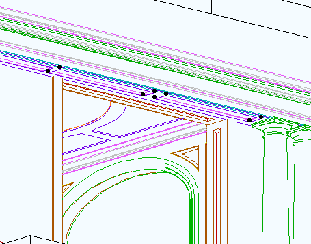
Placement Like windows have to be in a wall, skylights have to be in a roof. To place a skylight, set up the skylight tool and click over a roof.

OK, full disclosure, they don't have to be in a roof. If you place it outside a roof, you will get a warning, but the object will be created. If you move the skylight over a roof, it will become linked to that roof. The real meaning of the warning is that the skylight isn't linked to any roof, which pretty well defeats the purpose.

You will also be warned if the skylight overlaps an edge or a hole, including another skylight. Touching an edge is OK.

The skylight automatically orients itself along the slope direction, and tilts to match the slope angle. If the slope changes, the skylight adjusts itself. If you rotate or mirror the roof, the skylight follows. If you copy the roof, the skylights are copied too. If you rotate the skylight, well, you can't; it will re-align itself.

The Hole Roof holes are not as feature-flexible as wall holes. Hopefully future versions will be better. Hey, they're better than slab holes, which are in heaven waiting to be born.

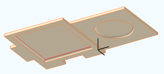
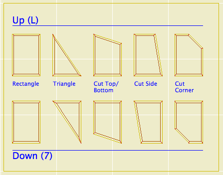
Skylight holes are always rectangular. There are round, etc., skylights in the AC library, but they cut rectangular holes, and the object fills in around the round part with roof-matching material. Trouble is, there's no way to not-draw the edge of the hole; the lines are there no matter what the skylight does. The current GDL doesn't offer a way around this.

The roof hole is cut with particular edge angles. The sides are vertical (fine by me), the top is horizontal, the bottom is vertical. You can select the roof or the hole and edit the edge angle normally. Trouble is, if there is any change in the skylight, the hole is regenerated from scratch and those default angles come back. And I mean any change, even a pen. Dragging it, stretching it too. If you change the roof slope, the skylight is regenerated, and the angles revert. If you copy a skylight, the new one will have default angles.

If those angles work for a given application, then good. But for the trim panel, we want perpendicular angles top and bottom, permanently. Again, GDL does not currently provide a way to control this. It can be quite frustrating.

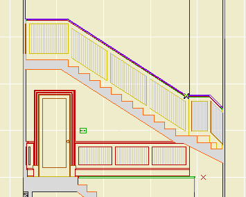
Layers Unlike doors and windows, skylights have their own layer. The roof can be hidden, and the skylight show. This is mostly for the good, but there is a side effect: If you select the roof and go to 3D, you don't see the skylights. If you select the skylight, you don't see the roof. (Where with doors and windows you get the opening and the wall either way.) Also, if you hide the skylight's layer, you still have a hole.

A typical skylight-type skylight should probably go on the same layer as the roof. The trim panel skylight can be handled as trim; if you want to see it in RCP, use the layer F Trim Crown.

Update for AC10: This story has been deleted from the templates. The new schedules in 10 can be placed as drawings, so the Schedules story isn't needed.

No, it's not every day we have a new story. It's also our first non-building story. I believe strongly in the building analogy of the AC project file, so I don't generally approve of stories for non-building purposes.

Here we don't have choice. This story is for Interactive Schedule elements, which can't be placed in any other window. You could handle this issue with layers, but you'd need an additional note layer. The pseudo-story down in the ground bothers me less.


Some schedules

You can also use it for this energy calculation method, which requires that the fills be in plan.

And anything else you think of that has to be in a plan window.

In framing plans, it's often helpful to show the walls on stories below with dashed lines. Especially roof framing. Well how do you do that.

More»

Update: This refers to the old version of interactive schedule, now called 'Element Schedules'. The principles are the same, but some of the names and menu commands have changed.

Zones are better than fills for area measurement because they can be updated when the walls (&c) enclosing them have moved.

(Zones are cool for so many reasons, but let's try to stay on topic.)

You can use Interactive Schedule to get the area of each story, of the rooms individually, and of the entire project.

I will describe two methods of floor area calculation: First, the gross area of each story, ignoring interior walls. Second, The total room area, or usable floor area, which will be less since the area occupied by partitions is not counted. There are different occasions to use each one.

More»

For a permit in Montgomery County, we need to do that Energy Worksheet thing, where we figure out the area of the walls and the area of the glazing, and determine the percentage of glazing. I feebly stabbed at getting this data directly from the walls, but I think it will require changes to the windows and more heavy calculation lifting than I think is warranted.

This method isn't automatic, but it's quick and reliable. It uses fills, hotlinked modules, and an Interactive Schedule. Which sounds complicated but it's not. I am offering it not as a standard but as an option, and as an example of lateral thinking. In other words, I think it's clever.

1. Draw fills on all the elevations, covering the habitable space. Use the layer Z Measurement. Cut holes in the fills for the widows and doors. Note: Doors without glazing are exempt. You don't need two fills, and you don't need to show the area.

2. In each elevation, create a module of the measurement fill. Save the modules in [Project]/1 Design/Modules/Energy Calc. When saving the modules, the name will default to the name of the section window, which is fine.

3. If you don't have a story below the footings story, create one. Use Hotlink Manager (File -> Modules & XREFs -> Hotlink Manager) to place each module on this story. They can overlap.

4. Select all the fills. Go to Calculate -> Interactive Schedule -> Preview. Choose the 'Energy Calc Fills' setting. You should see something like this:


5. Make a note of the two numbers. Using the Z Measurement layer, place an 'Energy Calc JM9' object (Location: Calculation RND). In the object settings, put the two numbers in. The object calculates the total wall area and the glazing percentage. You can also put in a target percentage and figure out how much glass is allowed.

You still have to look up the package number yourself.

So it's not automatic, but since the modules originate in the elevations, if you modify any of the fills you only need to update the modules and run the IS again.

The Interactive Schedule settings used by your local Archicad are saved as .iss files in ~/Library/Application Support/Graphisoft/IS Settings.

('~' means home, the house-looking folder named after you.)

But you don't actually use them there, so that's just FYI.

The standard IS settings, for the techniques I will describe here as they become available/I have time, are at 3 Resources (Onion)/Interactive Schedule. You use the IS interface to get these into your projects. Either: Calculate -> Interactive Schedule -> Settings...; or Calculate -> Interactive Schedule -> Preview..., and then the 'Import Settings From...' button. I prefer the second method; you can get from Preview to Settings but not the other way around, and I don't know why you'd fiddle with IS settings and then not want to see the schedule. (Maybe I'll just take that Settings menu item off. Let's move on.)

You can import multiple .iss's at once.

While it is possible to Change the Settings Folder, I would like explicitly forbid that you do so. Especially, don't use the 3 Resources/Interactive Schedule folder directly. If you do so and then make changes, you are Messing Things Up™. By keeping all the schedules settings local, you can mess them up all you want, as you need to, and you can always re-import the standard ones. That is, feel free to experiment.

I'll point out in passing that IS settings are handled very similarly to Work Environment schemes, and differently from attributes and library parts, and differently from conventional list schemes, which aren't library parts but are in the loaded libraries. It's really insanely complex. Maybe someday there will be a unified external asset manager for all this stuff, and the view sets too. And the display options.

2005-07-15.jpg

I've added a new layer combination to the templates, 'Stretch House'. It's intended to help when marquee-stretching the whole project. It simply shows and unlocks everything building related, while hiding the section markers and everything site-related. I hope you find it useful, or can at least ignore it.

Hotlinked Modules are another Big Feature I can't describe fully before moving on to giving you the derivative techniques. There are several English/Hungarian bilingual people whose job it is to fully describe to AC interface so I don't have to. Their efforts can be appreciated starting on page 421 of the reference guide.

Again, I'll just hit the high points.

Hotlinked modules are external project data placed in a project. In the host project they are treated as a single, uneditable group, with hollow, square nodes. They can't be edited directly in the project where they are placed. They have to be opened separately. This is a good occasion for running two copies of AC. Hotlinked modules are one story at a time of solo projects, teamwork projects, or module files. (There is an annoying overlap of meaning between hotlinked modules and .MOD files.) You can place multiple stories of a project, but each is its own module, placed individually.

The default behavior is for AC to check hotlinked modules for changes when the project is opened. You can change this, but don't. You can also do a manual update using the Hotlink Manager. Changes in modules are reflected in the project once the update is complete.

The Hotlink Manager is at File -> Modules and XREFs -> Hotlink Manager. It is here that modules are placed, updated, broken (turned into local, editable elements), and changed.

Breaking a module results in one big group. If you ungroup this group, you will get the groups within, as they were in the original file.

Modules can be mirrored, elevated, and rotated. When a module is rotated, zone stamps and text blocks can rotate themselves to compensate.

Placing a module is completely different from merging a module file. When you merge, the elements become part of the project. Hotlinking is an ongoing external reference.

Only Archicad files can be hotlinked. If you're placing DWGs, you need XREFs.

Applications to follow. Including:

Accessory structure alternates.

Energy calculations.

Showing a rotated garage level on the layout.

Note: Schedules in AC10 are completely different.

In here, where you can't see them, I have drafts of posts. The list of drafts can be viewed as the to-do list for the site. Stuff I know I have to tell you about, but I haven't gotten around to actually doing it. Many of the drafts relate to features of AC that are very powerful and proportionately complex. I don't want to regurgitate the reference guide, but I don't want to merely point you at the reference guide either. So there they sit. Since we're talking about powerful features, naturally there are other drafts of specific tips which have as prerequisites knowledge of the powerful features.

Anyway it's more important that you have the specific tips than the admirably balanced non-regurguitated, non-merely-pointing-you master post. Between the tips and the reference guide, you'll get the big picture. I hope.

One of these features is the Interactive Schedule (IS). We even had a meeting about it, since it's a lot easier to show and tell than to describe in text. I use the IS for door and window schedules, finish schedules, area calculations, and energy calculations. I also use is as a hack Find & Select for parameters within an object, so you can find all the crown elements that use WM-47 and change them to SM-28. Chances are some of these methods interest you, and I think they should, and I've been stalled in documenting them by the intimidating difficulty of the master post, which you'd think from the title would be this one.

So. The IS is documented in the reference guide beginning on page 374. Consider yourself pointed.

The ref guide does OK at telling you what the IS can do, but I think it's still up to me to point out its limitations. It is still very much a 1.0 feature.

• It only works in plan.

• It is modal, that is, you have to dismiss it in order to work in any other window, unlike, e.g., the Find & Select box.

• It can't do math beyond adding a column of numbers. No way to reduce an area by a percentage, e.g.

• The method for sharing schedule settings between projects is pathetic.

• It has too many poor interface quirks to list here.

It does what it does. In the future it will do more, and it's already way more accessible than the rest of the calculate menu.

More to follow.

PS, another big one is Hotlinked Modules. You need those for the energy calc thing I mentioned above. Sigh.

If you search Google for a simple question with a concrete, factual answer, it will give that answer ahead of all the usual links.

For example, I just put in 'how many square feet in an acre' and got '1 acre = 43 560 square feet'. Thanks, that's what I needed, bye. Other recent applications include comparing the land areas of Maryland and El Salvador. El Salvador is twice as big. And the Earth weighs 5.98x1024 kilos.

As of, I don't know, 8.1, Display Options can be organized into Combinations, kind of like layers, and Display Options can be saved with views. Our templates have been set up this way for some time, but I don't think I've ever cataloged the combinations. They're just as standardized as anything else. Highly.

In the DO dialog, there are two panes, Display Only and Display & Output.

The Display Only options do not vary among combinations. Real quick: Intersections are on, Walls are contour lines, all the handles are on, section depths, detail boundaries, and markup elements (never used 'em) are hidden.

Display & Output options is where the action is. Rather than describe each combination, or heaven forbid build a table, I'll describe the A1/A2 combination, then how the others differ.

In A1/A2, which gets saved with plans and elevations for output: Beams are Contour Lines (no reference lines), Line Weight is Hairlines (they get turned True in PM), all the Fills are Vectorial, Doors & Windows Show with Dim, Zone Polygons are None, Zone Stamps Show, Section Markers are As in Settings, Column Symbols Show, Fill Background Color is By Element Setting.

Working Plan/SED is the same as A1/A2 except Beams are Entire Beam (ref lines on), and the Drafting and Cover Fills are Bitmap.

A3, which gets saved with wall sections, is the same as A1/A2 except the Fill Background Color is Transparent. (This means no fill backgrounds. Use Solid Fill for white masks. To mask with a pattern fill, you need two overlapping fill elements.)

A4/S0/M/P, which gets saved with RCPs, mechanical, plumbing, and foundation plans, is the same as A1/A2 except the Doors & Windows are Reflected Ceiling.

S, which gets saved with framing plans, is the same as A4/S0/M/P except the Cut Fills are Separators only. This turns the wall fills off, but shows a line at the joint between, e.g., concrete and stone. Fill backgrounds are on, so masking fills will work.

Site, which gets saved with site plans, is the same as A4/S0/M/P except the Cut Fills are No Fills. You will only see the effect of this if you show walls on the site plan.

A quirk of DO Combination management: You can't rename them. You have to Save As, which leaves the old one in place, and then you have to redefine the views that use the renamed combination. Then you can delete the old-named one. Also, I haven't figured out how to import DO combinations from other projects.

Another thrilling episode of Template Update.

• I put autotexts in the Project Title detail window. Instead of defaulting to 'Somebody Residence', it says {CLIENT} {PROJECTNAME}*. Similar for the address.

• I changed the weights of the white pens (10, 20, 40, 60, 80, 91) to 0.0 mm. This shouldn't have any negative side effects. The idea behind white pens is they disappear completely, and if the weight isn't zero the can show up against backgrounds. So the practical change is that invisible things become even less visible. That's probably OK?

* As usual, curly brackets mean angle brackets, since Movable Type treats everything in angle brackets as tags.

Link

We entered via the West building to avoid the line and so came at the work from across the atrium. My first impression is annoyance that they have the exterior doors blocked unceremoniously with one of those velvet ropes. They don't want you outside. My annoyance notices the reflections on the glass, making it hard to see outside, I'm thinking, nice try but no. Two of the domes are constructed so part of them are inside; one slightly, one about a third. This emphasizes the isolation of the rest of the work, behind the reflections and the ropes. The domes fill the courtyard, bumping against even more walls outside. The only ground space is near the door. Again, if you would open those doors, we could get to work. The domes are very dense to left, no ground space, all running into each other. The slate varies in thickness from 1 1/2" to 4". I try to see if the slates that 'span' the glazing were cut from one piece and carried around. Some were, some were not. Make up your mind. At my height I can see the top stone of the domes, they appear solid, I thought they would have holes. I process that the roofs are solid. Probably pretty dark in there. The height of the domes is just beneath that of the wall enclosing the courtyard; remember walking by the wall on the other side. All the same height. We go upstairs, past the Toulouse Lautrec line, to look down out the windows. Surprise! They do in fact have holes. The top stones are ground out in the center; from the side they appear solid, from my height or shorter; the slate tapers to the edge of the hole, which is sharp and crisp, no edge visible. The holes are perfectly round and very black. They appear substantial, not empty. Somehow it is a relief, that the holes are there, now the work seems more in keeping. There are nine domes. They crowd the courtyard, overlapping, intersecting. Each one is incomplete, interrupted. They could be ancient.

You can see why domes would be chosen. Leaving, you notice all the other domes around. It's a high-visibility commission. At some level you want to fit in. It should read. It's urban and permanent. If there aren't so many, and a little too big, they will sink into the background. In the wilderness they could be small. Here they need to be stranger, wilder, awkward, crowded, maybe isolated. They recall the hole-type projects, as well as the cairn and stacked-up sphere type, if you consider that they might be mostly buried.

All Entries | 1 | 2 | 3