On Land

Environment Information
At Rill Architects we run ArchiCAD on macOS. If you work at Rill, this is your stuff. If you don't, but you work in ArchiCAD, you may find something interesting. Anybody else, I don't know.
RSS
May 2005 Archive

F Trim2 is for trim elements you want to show in plan. Two applications off the top of my head:

• Pilasters. This gives the option of turning off the pilasters in structure plans, etc.

• Panel Walls. Where you have pilasters, you often have paneling, and if you show the pilaster without the panel you get a gap.

Alright that's only one application. One and a half maybe.

Location: 06 Wood & Plastic : 2D Wood

This object makes it easier to fill in stud walls in wall sections. It combines plates, headers, blocking, drywall, sheathing, and insulation, in any combination, for 2x4 or 2x6 walls.

At the top you can have a plate, double plate, or nothing. The bottom has these options plus a header, and an optional anchor bolt for the plate.

You can show batt insulation or not, and show mid-height blocking or not.

Outside the studs on either side you can have a fill for drywall, plywood, or neither. The perimeter line on both sides is optional. If you are placing the object in an existing wall, you usually don't need these lines.

This object is another aid to developing wall sections while keeping them model views. If there's anything it could do that isn't, let me know.


UPDATE 12-22-06: Added the ability to extend the side fill along the ceiling on either side, even at an angle.


The spot at the end stretches the length, and the spot in the middle adjusts the angle.

I was going to patch up this post, but I decided to do a new one. The old one is mostly right, I just wanted to add...

• In AC9, there is a menu command for Create Independent Detail. That means you can have a shortcut for it. In our keyboard setup, it's Ctrl+D. (What. Oh. Tools menu. Please don't do it that way. I hate menus.) Also nice, when you create an independent detail, it opens automatically.

• For some reason, most of my projects open new independent details at absurdly zoomed-out views. Like the window is a million feet across. I can't fix this, it's not stored in the prefs. It's always a good idea to work near the origin. You can zoom to the origin quickly by placing an object there and then doing a fit it window.

• Wall sections should be Sections. It's so clear to me now.

• IDs. They still need to be unique, but the ID will now take up to 31 characters, so you can be very non-cryptic. You can have spaces, though I don't use them. I like it to be clear that the first word is the ID. To review, use the ID to say what type of detail is in there, with a number so maintain uniqueness. Use the name for a fuller description. Eave1 Typical, Eave2 Shed, Eave3 Porch.

I have been drawing all the engineering details myself, based on their sketches. I keep these separate by beginning all their IDs with "S_".

• Detail markers: For areas, use Detail Area JAM9. For flags, use Detail Flag JAM81. These markers show the ID in Archicad and the drawing/sheet number in PM layouts. For assemblies, use Assembly Marker JAM81. This marker maintains the ID, which is the same as the (non-autotext) drawing number in each assembly detail. It also gives the sheet number, which is automatic. I have developed the habit of putting my schedules and assemblies on sheet A3-1, so they stay put as sheets are added.

• Remember you can open a detail from any marker, not just the original one.

• The biggest hassle with the detail tool is the fact that you can't put a detail marker in a detail window. Maybe someday. If you need to call out a detail within a detail, use an object. Remember the autotext referencing hack.

2005-05-27.jpg

A label to show the elevation of the top or bottom of a slab.

It works in plan or in section, and changes its form depending on which kind of window it's in. It can give the elevation to project zero or the home story of the slab.

I made it in an attempt to overcome one of the big limitations of the Level Dimension tool: It can't read the bottom of an element. If you can read the bottom of an element, you can show live ceiling height dimensions in the RCP. I'm also attempting to overcome one of the big limitations of the level version of the regular dimension tool in section: It isn't truly associative and doesn't move when the slab does.

In creating this label, I discovered and did mortal combat with several disabilities in Archicad, and especially in the label functionality. In the end, it doesn't do nearly what I want it to, but it's (mostly) not my fault. The section version works well for showing ceiling heights, as long as the slab is on the same story as the room. To use the plan version in RCP, my original primary goal, involves additional layers, or commits me to fussier modeling of ceilings than is otherwise needed, and is tedious to maintain.

(I wrote a mini-white-paper mapping the related Archicad disabilities on Archicad Talk, if you're interested, here it is.)

So even though the plan version has three broken legs, the section version is passable, so here it is.

Use it as an associated label, of course. Choose to label the top or bottom, to project zero or the home story zero.

In plan, you should only use it to label the bottom of a slab; for the top, the level dim is far superior, since it can read hidden elements.

The plan text can moved anywhere, and will flip around depending on what quadrant it's in. Sorry about the separate X & Y editing hotspots, for some reason they can't coincide in labels. I regrouped and got it working; the current version is for AC10 or above.

When placing the label in section, it will always appear at the lower left corner of the slab. If you are dimensioning the top, you need to move the label manually.

Download (AC10)

Sheet S0
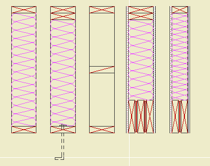
The foundation plan shows the foundation walls, footings, slabs, and related annotations. Everything that touches the ground. It can be combined with the first floor framing, but an independent foundation plan can give more information with less clutter. The layers, layer combination, and views required are included in the templates.

• What Shows.

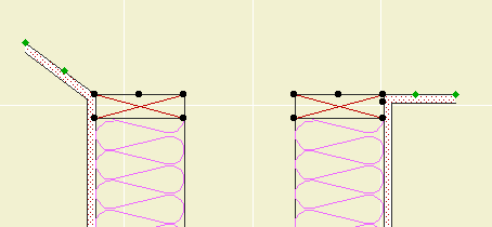
• All plan walls, A Wall Ext, A Wall Int, S Wall2.

• Steel columns which rest on footings, S Col Steel. Other columns remain on S Column.

• All footings, S Footing.

Framing plan layers which should be hidden in foundation plans: S Beam, S Framing, S Column, +S Struct Note.

• Annotations.

• Foundation dimensions. It should be possible to use the foundation plan to stake the project. When using a foundation plan, you should only have architectural (interior) dimensions on the A1 basement plan.

• Wall and footing sizes.

• Dimensions to all columns.

• Graphics and notes describing all slabs and their reinforcement. Elevations of slabs to project zero. Use fills to show reinforcement. Use a background of pen 91 on text blocks to make them legible when placed on fills.

• Detail markers calling out wall types and other relevant details.

Annotations belong on +S Foundation Note. Annotations which also show in the framing plans belong on +S Note All.

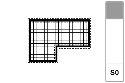
The foundation plan is typically generated from the same story as the first floor framing, so it requires a separate layer combination, S0 Foundation Plan. The display option combination, S Foundation, differs from that of the structure plans only in that the cut fills are Vectorial Hatching instead of Separators only.

The foundation plan's sheet number should be S0 (zero).

I've made a couple of changes in the templates which affect how columns are layered. These changes are important, especially if you are in the habit of placing architectural columns on the S Column layer.

1. S Column no longer shows in architectural (A1) plans. With this change in mind, I also want to clarify the difference between architectural and structural columns.

2. There's a new layer, S Col Steel, for columns in the basement that need to show in the foundation plan.

If you come to me and ask why your columns are missing, I'll know you didn't read this.

More»

2005-05-20.jpg

Gives the ability to draw a custom muntin pattern and drop it into a sash. Improves on slabified muntins in that it will move when the window opens, and can be hidden in wall sections.

Makes two EXTRUDEs based on drag 'n' dropped points, one of interior material, one of exterior. Intended to be called by sash macro. Placed by the lower left corner, by the middle.

User needs to place shape points after PUT in 3D script. Set A, B, ZZYZX. ZZYZX is the thickness. Set TOLER if necessary, default is 1mm.

2005-05-06.jpg

Another Hotfix. It's on the Onion, next to the previous one. Here is the list of fixes. I was tragically victimized by the disappearing label thing, so good.

Again, Everyone should run this. Again, You can run it from the Onion, rather than copying it to your machine.

Again, (You can check for updates any time by choosing Check For Updates from the Help menu in Archicad.)

I love the clipboard. I won't paste in my rant about the version numbering, although it still applies. Yup, 9.0.0 v1, now and forever. Watch that build number though.

Take the Archicad competency test. Whee.

I thought it was pretty tough. I managed an 86.

House rules: Since each question is timed (90 sec), I think open book/open Archicad is permitted. If you can open the Attach XREF dialog and figure it out in 90 seconds having never looked at it before, more power to you. The point is to learn anyway.

Unfortunately, they don't tell you which things you got wrong. You'll probably have a feeling though.