On Land

Environment Information
At Rill Architects we run ArchiCAD on macOS. If you work at Rill, this is your stuff. If you don't, but you work in ArchiCAD, you may find something interesting. Anybody else, I don't know.
RSS
October 2005 Archive
Sheet S1
Rules for framing plans. Foundation plans are slightly different. Roof framing plans are very similar. I'll have a separate note for them. I wonder what the difference between 'slightly different' and 'very similar' is.

• Walls. Display of walls is controlled by Display Options. The 'Cut Fills' option should be set to 'Separators Only'. The walls will be clear, with lines at the separators; for example, between concrete and stone. Use the 'S' Display Option Combination.

• Bearing Walls. To show a bearing wall, draw a fill on top of it. This is a non-associated, additional element. Use the fill '*Masonry Block', with a background pen of 50. Use the layer +S Struct Note. So: Walls are clear, except bearing walls, which are shaded.

• Rafters & Joists. Fill elements of the fill 'Joists 16OC' or 'Joists 12OC'. If you need other spacings, you need to make more fills. The fills go on the layer S Framing, which only shows in the framing plans. Rafter and joist placement is diagrammatic.

• Rafter & Joist Labels. Object 'Joist Note JAM9'. With the joists shown as fills, you don't need to show the extent in the note object, although it has that option.

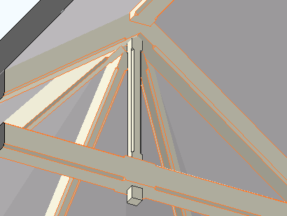
• Beams. Beams should generally be modeled and labeled in sections. Use the objects Wood Beam JM9 and Steel W Shape Beam JAM9, etc. Most beams should be on the layer S Beam, which shows in section. If the beam is just used as a note, place it on S Framing.

Beams can reference their calculations by use of the ID tag in the objects.

• Annotations. All annotations should go on the layer +S Struct Note, unless you want an annotation to show in the foundation plan simultaneously. In that case, use +S Note All. Use a background of pen 91 on text blocks to make them readable when placed on fills.

• Structure Notes. Loads, criteria, etc. are part of the General Notes PDF. Specific notes can be added to the plans using text blocks.

Location: 05 Metals

(Old object, new write-up.)

An object for modeling and annotating W shape steel members. It should behave similarly to Wood Beam JAM9. So I can copy and paste a lot of the documentation. Also, that post has screen shots.

More»

Location: 15 Mech-Plumbing

A very simple residential water heater. OK, it's a cylinder.

The reason to use it is it knows an array of standard capacities, and the tank dimensions for each. You can stretch the object in plan or 3D to change the size. You can also enter a custom size and dimensions.

In plan, the circle can be labeled with the capacity, or just 'WH'.

It's a slight improvement on WaterHeater JAM9; note the subtle spelling difference until I move the old one.

Obsolete. Use Stair Body JM9a. instead.

Location: 06 Wood & Plastic / Railings & Stairs (I'm thinking about moving it, since it's not really a fine detail-type thing any more. More like a missing tool thing. Not to mention, it could be concrete. I really wish the object browser could handle aliases. As for now, there it lies.)

A very basic (in a good way) flight of stairs. An incremental improvement on Stair Stringer JAM8. You can still use it as a stringer; just make it thin. I changed the name because I use it more often for actual stairs.

Sidebar: There's a stair tool (Technically, the StairMaker add-on), which you should never use. Then there's ArchiStair by the very capable and friendly Cigraph, which is like a good StairMaker, only better.

I recently used an ArchiStair spiral stair for which I was very grateful, but generally I am skeptical of full-service add-ons for highly detailed building parts. No matter how many options, configurations, and details are offered, you will soon run into a custom situation where the add-on doesn't quite make it.

I would rather have more, simpler, separate elements. (Well, no, I would rather have one element do everything by magic, but it's not realistic.) If you run into a freaky custom railing, you can focus on that without wrecking the whole stair. And: In design development, you can show just a simple stair, leaving the details for later, where they (the details) belong.

This is consistent with a general principle of Archicad's design, our workflow, and how projects are actually built. Big, chunky stuff comes first: Walls, slabs, roofs, the basic geometry of stairs. Fine detail comes later, and is applied to the big stuff: Trim, finish floors, newels and railings.

So: The Stair Body object is like a slab tool for stairs.

Another major basic-yet-detailed building part is the chimney. See what I mean? End sidebar.

Now we can talk about the object.

More»


Location: 13 Special Construction

For cutting a limited chamfer in a corner of something. Or unlimited, but you could do that with a slab. Use it with Solid Elements subtract.

By default, it's vertical, but you can use any Slope between 0º and 90º. If the object isn't vertical, you can also set a Rotation angle. (If it's vertical, you just rotate it in plan.)

Even if the object isn't vertical, the 'length' of the cut is controlled by the height parameter. This is a little awkward, but it's made less so by having the length stretchable at any angle.

For sloped cutters, it is highly recommended to throw them down and fix the placement in section. To do this, you need to temporarily switch the SEO layer to solid in the layer dialog. In wireframe mode, you can't tell where the object is cut by the section, so you don't know where to grab it.


Grab the object by the midpoint, and drag it to the corner.

The thickness of the object is the standard width parameter. Often you will have a dimension for the cut along the face of the element being cut. For this, use the Ortho Cut Length parameter. This parameter and the thickness are hooked together, so you can use either one. The Ortho Length is editable in plan.

Using a bunch of these objects I made this:


I also used it on the newel module thing.

May 9, 2008 update:

In the image above, the vertical piece was done using four separate objects. To simplify this move in the future, I added a parameter for Multiple Corners. This will arrange up to four cutters in a rectangular pattern defined by the X and Y Dimensions.

four cutters

Place one of these and tilt it, and you can chamfer the strut of a bracket:

chamfered bracket

Download (AC11)

Location: 04 Masonry

Put these on the corners for that authentic Potomac builder puffball look. Or maybe you could use it for a nice house, who knows.

Pretty simple; length, width, height, thickness. The Form can be Stack or Stagger. Stagger is the alternating one.


Stack...Stagger...Stack...

If Stack is selected, you can set Symmetrical to on or off. When on, it causes the width to equal the length.

If it were me I would use the layer F Trim Ext Mid. Place one object to cover all the affected stories.

All these are set up in the templates and favorites. If you notice Arial anywhere, you are missing a font on your system. If there's Arial and you don't notice it, consider getting a job using AutoCAD.

Notes & Labels: Lucida Sans

Dimensions: Tahoma

Drawing Titles and Plan Titles: Times

Drawing Number in Title: Futura

Drawing List: Lucida Sans

Room Name: Times

Sheet Number: Futura

Title Block Data (Except Firm Name): Ocean Sans Std Light

Title Block Firm Name: Times

Project Title (Cover Sheet): Goudy Old Style


I built this newel out of ordinary stuff. Crown and baseboard objects, walls, a mesh for the top. In plan, there's a square fill. All the elements go on the layers they would if placed directly in the project. The model parts are on A Stair3, and the fill is on A Stair Rail.

The newel is all alone in a separate project file. I hotlinked it into the main house project, and copied it around. There are eight of them.

It is easier to maintain than if I had saved the whole thing as an object, which was my first idea.

I am also using the newel PLN to generate the section and elevation details of the newel. Can't do that with an object. Remember you can have drawing links to different projects.

When I needed a half-version of the newel: I created yet another separate, blank project, and hotlinked the newel into that too. Then I placed a big slab and SEO-subtracted away half the newel. Then I realized that the plan fill was still whole, which is no good. I broke the hotlink, which leaves ordinary elements. (So I could have simply merged it after all.) I adjusted the fill to cover only half the newel. Then I hotlinked the half-newel project into the main house as above. (If I change the whole newel, I'll have to do the half over. Not ideal, but the alternatives aren't either.)

Something to think about...

Location: 06 Wood & Plastic/Columns & Pilasters

A decorative column or pilaster, with an optional panel, and mouldings for the top, base, and panel.


More»

Location: 06 Wood & Plastic/Brackets

A bracket that looks like this:


You can set the width (X), thickness (Y), height, height and depth of the nose, and width of the base. That's about it.

(By the way, the arch is slabified.)

Location: 06 Wood & Plastic

One, or many, rafter tails or pergola elements. A huge improvement over Rafter Tails HOOV8.


More»