On Land

Environment Information
At Rill Architects we run ArchiCAD on macOS. If you work at Rill, this is your stuff. If you don't, but you work in ArchiCAD, you may find something interesting. Anybody else, I don't know.
RSS
July 2007 Archive
Ceiling Switch
In Model View Options
Location: 01 General / 2 Drawing Tools

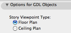
Among the least heralded new features of Archicad 11, tucked into the bottom of the Model View Options dialog, is the modestly named 'Story Viewpoint Type'. Not heralded at all, in fact; there's no mention of it in the New Features Guide. I understand why they don't want to call it out too loudly. Its impact is rather narrow, and the Archicad library itself makes very limited use of the feature.

Right, what is it. It's the long-awaited (by me) environment switch to put the floor plan window in 'Ceiling Plan' mode. Wouldn't it be nice if things could draw themselves dashed in plan and solid in RCP or vice-versa. Less tracing, less maintenance, more unity. This is a pet issue of mine, so I'm happy to see it, even in its narrow, modest, unheralded current state. I'm calling it the 'ceiling switch' because no one knows what 'Story Viewpoint Type' means.

The switch gives the opportunity to have objects draw themselves one way in plan and another way in RCP. But: Only objects, which includes doors, windows, and lamps. It does not apply to regular modeling elements such as slabs and beams. Keep hope alive.

I've made several objects which take advantage this tech, and I plan to retrofit more as we go.

Ceiling Line JM11

The first one is, a line! Haha! I know, if things are more unified you should draw... less! It's ironic. But there's more to come and this serves to illustrate the basic idea.

Ceiling Line parameters
There are four parameters; a pen and linetype for plan, and a pen and linetype for RCP. Any of the parameters can be set to "0", which means the line will be drawn using the object's settings (the pen and linetype shown in the Info Box). You would either have the plan use the object settings and customize the RCP, or the other way around. (Don't pay attention to all that 'Missing' and 'Transparent' stuff. It's just how AC interprets the zeroes.)

Linetype tile
Using the default settings as an example, the object is set to use the 'Dense Dashed linetype, and the Plan Linetype is set to "0", so the line will be drawn with 'Dense Dashed' in plan. The RCP Linetype is set to 1 (Solid Line), so in ceiling mode it's drawn solid.

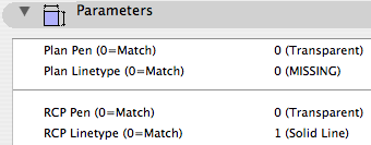
You could do the reverse: Let the RCP use the object settings and customize the plan parameters. Either way.

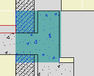
What's it for? Roof overhangs. You have to draw them anyway, because showing the roofs themselves is a mess. Use this object instead of a line, and get the overhangs in plan and RCP simultaneously. And: Miscellaneous ceiling lines such as those in an attic.

Template Changes

We need a new layer, which is A Ceiling All. This layer shows in plan, RCP, and all the model combinations.

To handle the ceiling switch itself, we need a new Model View Option combination, which is A4 RCP. In previous versions, the RCP used A4/S0/M/P; now that one's just S0/M/P. When migrating a project, you'll need to create this model view combination and assign it to the RCP views.

Location: 04 Masonry / Chimney & Fireplace

It's very hard to describe this object independent of the whole chimney process, but I'm going to try. Once this guy is written up we can look at how it, the firebox, and the flue work together.

This version is superior to the JM9 version in that the flue is better oriented with the firebox. In other words, it's less wrong.

The smoke chamber object makes a void. It is intended as an SEO operator. Like the flue, it's supposed to drill a hole through the chimney material.

Smoke Chamber plan
Parameters in plan
The Length matches the width of the firebox opening. The Width matches the firebox depth. Firebox Back Width matches the back width of the firebox. The back width is editable in plan.

The object is wider than its Width by the value in the Firebox Wall Thk parameter.

So that's four parameters that the smoke chamber takes from the firebox.

Likewise, Flue Width and Flue Depth should correspond to whatever you're using for the flue.

Smoke Chamber section
Parameters in section
Height is simply the overall height. The bottom elevation of the smoke chamber should match the top of the firebox.

Throat Height is the dimension of the plumb portion of the front of the object. Damper Height is the height of the sloped portion, which straightens out again at the flue depth.

Shelf Depth is measured down from the Throat Height. It carves out the place where you have to draw in the curved bit of mortar.

Throat Adjustment doesn't make sense until you see how the smoke chamber and firebox subtract from the chimney material. It's there to keep that vertical edge with the firebox wall, so there's no excess wall stuff hanging down.


Place the object on the layer A Flue. Use a non-printing pen (60 is good), and the material you want to see on the inside of the subtracted space (Brick Surface Color is good).

A Flue shows in plan, so the non-print pen hides the object in output. It also hides the weird lines on the surface of the object in section, which would be visible in the targeted chimney material. You can choose to show the smoke chamber's "flue X" by turning on Show Flue.

Template View Map orientation session.

Remember that views are viewpoints (stories, sections, details, etc) plus user options such as scale, layers, model view options, and dimension standards. Views become drawings in layouts.

We need views for each kind of output we're going to produce. Additionally, we want views for the various modes of work we do in the model.

We do the same kinds of output over and over, and the same kinds of model work. When you're doing the same things all the time, the templates should support you by getting a lot of it started.

These are the top-level subsets of the template view map:

• Working: Views which use the 'Working' Layer combinations. Use these views for day to day work on the project.
• Schematics: Intended for output in the schematic design phase. These views default to 1/8" scale.
• CDs: Intended for output in the Construction Documents and Design Development phases. The plan, section, and elevation views default to 1/4" scale. All other output subsets are included; interiors, structural, RCP, etc.
• Schedules: Views of schedule viewpoints for windows, doors, finishes, etc.
• 3D Views: Perspective, axonometric, top views from the 3D window.
• Note & Title: Title blocks, drawing list, vicinity map, project information, other annotation-type drawings.
• Background Plans: Stripped-down plans for DWG export if anyone asks.
• Binder: Small-scale plans and elevations for the post project binder.

Within the Working, Schematics, and CDs subsets, there are cloned subsets relating to the various viewpoint types, including at least:

• Plans
• Sections and elevations
• Wall sections
• Details
• Reflected ceiling plans
• Interior elevations and enlarged plans
• Electrical plans
• Structure plans

The Schematics and CDs divisions are named after the sheet they are published on: A1 Plans, A2 Elevations, and so on. Note the symmetry with the Schematics and CDs subsets in the layout book.

The divisions within the Working subset correspond to these output divisions: Working Plan, Working Elevation, on like that. (Working Model gives the whole model with no annotations.)

The working subsets are for us, and the others are for the documents.

I hope this illuminates the view map structure in our templates.

Late fourth birthday present to itself. I wanted the tags to be more prominent and I got carried away.

Also more eye-catching is the RSS feed link, that orange thing in the upper right. If you're not using RSS, you should. Briefly, RSS makes it easier to keep up with multiple web sites, because it lets the sites tell you when something has changed, rather than you remembering to go and look. At this point it is difficult to find a site that doesn't publish a feed. Safari can handle RSS feeds directly, or you can use a dedicated reader. There are free and non-free readers for all platforms. I use the non-free and fantastic NetNewsWire. More on RSS here.

Another unsolicited testimonial: In the course of this revision I had an excellent email support interaction with Movable Type. Quick, attentive, and thorough.

What else. I did the whole thing in Coda, which I found quite pleasant. I'm not enough of a pro to appreciate its limitations yet.

Hey Microsoft, your browser is an obnoxious pain. HTH.

Let me know if something acts funny.

paradise

This will go live when we move to Archicad 11. It doesn't have anything to do with 11 per se, but it's easier to make organizational changes at a version break.

On 3 Resources / AC, we have a new folder called External References. This will hold all the external drawing and annotation resources which are used in the templates. These are:

• The Abbreviations PDF on the cover sheet.

• The Drawing Symbols PLN. This generates the views that wind up as the symbol keys on the cover sheet.

• The General Notes PDF for the T2 or T3 sheet.

• Standard assembly detail modules, which are hotlinked into detail windows.

• Electrical Plan symbols.

• Probably other things.

This is all the standard stuff. If a project has external references particular to itself, those go in the project folder.

In the current system, if you can call it that, we have these resources in at least three places and it's a hassle if you need to relink something. In the 11 template it's clearer.

Profile Patch 1
This is a complicated condition. It's surrounded by ordinary modeling elements, but it's difficult to weave those elements together such that it all cleans up and looks correct in section.

Here's the ordinary elements by themselves. I put in some detail objects for clarity:

Profile Patch 3
The joist deck slab is basically right. The concrete slab needs to reach in to bear in the foundation wall. That edit is easy, but then we need concrete below the slab to reach the top of wall, and above to reach the sill plate behind the veneer.

The top of the concrete wall is in the right place for the joists, but it's part of a composite with the stone veneer that needs to reach the bottom of the slab. Likewise, the frame part of the upper composite is right, but the stone needs to come down.

There are several ways to solve this with walls and slabs. I'm not going to go into them, except to say they are all rather unpleasant, typically involving 3-5 elements, some of which will be new composites. Sad work, especially when you have to take the whole mess around a corner.

An alternative would be to use fewer elements, get it looking OK-but-not-great, and then use a patch to make it pretty. As you know, you create a patch from existing geometry, and then use 2D editing to force it to look right.

(To be clear, I'm not against patches. They are hacks, but often essential hacks.)

Here's the thing though: If you're going to push fills around to make the condition look right, why not do it in a custom profile? It's still a 2D shortcut, but you end up with a 3D piece you can use wherever you find the condition. It will miter around corners and generally behave like a proper modeling element, displaying correctly no matter where you view it.

A custom profile can be arbitrarily complex, made up of any fills in any shape, and when it's placed it will clean up in section to the like fills it touches. Its surfaces will clean up to like surfaces in elevation.

Profile Patch 4
In this example there are six fills, all cleaning up properly with the adjacent elements. I changed the background color for clarity, but you can still see the cleanup is working.

Profile Patch 5
1 is the concrete which completes the slab and forms the stem wall. 2 is the stone which matches the composite skins above and below. 3 is Empty Fill meeting the empty composite skins. 4 is a special optional Empty Fill. It meets the joist deck slab. Of course, you could extend the slab 1/2" to fill this space. But by putting this filler in the profile, I can keep the slab at the inside face of the frame wall, which is an easier edit.

Such a profile could used with a wall or a beam element. Use a 3D-only layer such as A Wall3. It's probably easier to place the wall/beam on the lower story in this case. If you use a wall for the profile, set its Floor Plan Display to 'Overhead All' so it stays transparent.

Conclusion: If you're facing a multi-fill section patch, see if you could use similar fills in a custom profile instead.

natlanticbloom.png

Location: 01 General / 1 Graphic Symbols

UPDATE 2019-11-12: Replaced the solid fill called by name with the global variable for the first solid fill in the fill list. (This might be 100%, 'Solid Fill', 'Foreground Fill', etc.) Now the mask fill won't fail if the 'Solid Fill' isn't available. This version is for Archicad 22.

UPDATE: Backsaved version for AC9.

Same features as the AC9 version, with a simplified interaction for getting the loop off center.

Cutline JM10

More»