Update your bookmarks.
Let me know if something doesn't work.

All Entries | 1 | 2 | Older »
Ignore this.
Border, dk blue: #000066
Banner background: #0000FF
Surrounding posts: #99CCFF
Body text: #003366
Body text link: #FFF
Body text link hover: #3300FF
Body background: #D1EEFA
Banner Link hover: #99CCFF
With Gravity on, you can placed associated Level (Z-elevation) Dimensions on slabs, roofs, and meshes.
(As with regular dimensions, the text can be customized, breaking the association. I use these on reflected ceiling plans, since you can't get gravity to detect the bottom of an element. A wish. (There might be a way to use a label for this, but I haven't tried.))
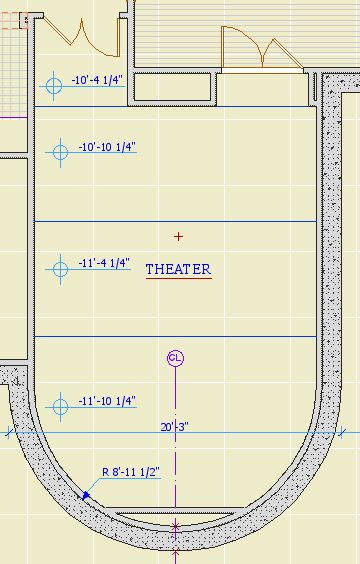
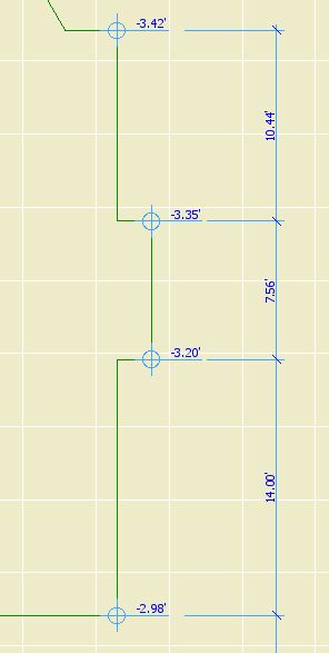
You should use associated Level Dimensions to show all the surface elevations in the project. Here's the slab stepping down in a theater:
You can also put grade elevations on a site mesh. Here I used the house outline as a guide to show the elevations at the corners. I don't know whether we should actually do this, but it sure is easy. (Also, there should be a way to display sea level, but I can't find it.)
UPDATE: To show sea level, assuming you have it set properly in Working Units and Levels: After placing the dim, select the text. In the Info Box, click the flyout at Measured Value and choose Autotext. click the flyout to the right in the same tile and choose "to sea level". I didn't bother updating the picture, so you'll have to take my word for it.
To place an associated Level Dimension, activate the tool and turn gravity on for the desired target, by clicking the slab, roof, or mesh gravity button. Then just click on what you want to dimension.
If the dimension value is wrong, it's because gravity detected the wrong element. For example, you're trying to get the main floor deck elevation and gravity is finding the ceiling. Hide the layer of the element that's in the way.
Tip: If you select the Level Dim and hold the mouse button down, you can see what element it's associated with. (This works for regular dimension ticks too.) This helps you track down elements in the way. Select the interloper, then use the Quick Layers palette to hide its layer.
There are different ways of doing this, but the first I've been pleased with is the use of Quicksilver.
With Quicksilver running, invoke it (Ctrl+Space, unless you changed it). Type enough of the word "Archicad" to have it pop up on the left. If you have multiple versions, select the proper one from the list below.
Tab. Type "Lau". You should see "Launch Another Copy". Return.
There ya go.
If you don't see the "Launch Another Copy" option, quit Quicksilver, relaunch it, and try again. I have seen this happen after launching another copy, quitting it, and trying to launch again. Seems like a bug.
It isn't needed, but there are times when it's very convenient. You can quickly copy and paste from another project. You can open a placed module without closing the host project. It comes in handy.
Run multiple copies at your own risk. Keep your head on straight. Don't run two all the time. Don't open the same file in two copies at once. Quit the second one when you're done with it. Pay attention to where the second copy is on the dock. All these warnings go double for people who are easily confused, you know who you are.
Another tip: When quitting two ACs, let one quit all the way (the black triangle disappears from the dock) before quitting the other. If you quit them both simultaneously, you're asking for corrupted preferences.
Quicksilver is a "launcher", but it does much more than launch applications. It figures out everything about your computer, then hooks everything together so you can perform actions in an intuitive manner. It knows your files, your songs, your address book. You can find a file, say mail it, find the recipient, and done. No Finder, no dragging, no Open dialog.
I've had it for one day, so I'm no expert. Here's 3 links.
It's free. It's in beta, so you'll might hit a bug, although I haven't. It will also tell you to update every once in a while, which you should do.
It also offers a simple way to run multiple sessions of Archicad.
Location: 01 General : 3 Drawing Tools
Very simple, just two (presumably) vertical lines. It has but one setting, the width of the column on paper. Saves you the hassle of multiplying by the scale to figure out how to space the lines yourself. The lines are detectable; wouldn't be very useful otherwise.
You can copy and paste elements between facing sections/elevations, and easily put the pasted elements in the right place. Examples: Room names in sections, and elevation outlines.
The trick is to mirror the elements across the global origin.
Hotspots do two things:
1. Placing a detectable point where there isn't one.
2. Making a point detectable in PlotMaker, for the purpose of aligning drawings to one another or to the layout.
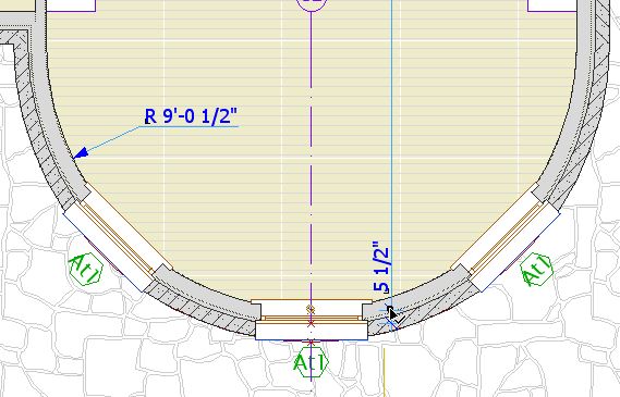
In practice, I use very few hotspots. I try only to use them where they will be permanent. A common example is a hotspot at the maximum of a curved wall, so the wall can be dimensioned.
Such permanent hotspots should be locked.
I almost never use them as a workaround, and if I do, I delete them immediately. If you get in the habit of placing a lot of hotspots and leaving them around, the workspace becomes cluttered with extra detectable points, making it harder to be sure you are detecting the point you want, leading to errors.
Further, hotspotting an arbitrary point to detect it is usually not needed. Special snap points and the ghost story make it possible to detect any point worth detecting, and you can move the origin to "transmit" a point through stories. You can also use CenterPoint JAM9 as a hotspot, and it has the added benefit of showing on multiple stories. And really, how often do you need to detect a point that's truly in the middle of nowhere?
If you've gone on a hotspot binge for whatever reason, you can delete them all at once: Activate the tool, Select All (Cmd+A), delete. Since your permanent hotspots are locked, the won't be harmed in the purge.
Hotspots are also created by certain variants of command clicking. This has occasional usefulness, but it more often happens by accident. Be aware of it so you don't wonder how you made a hotspot without the hotspot tool.
The hotspot on the wall is in line with the red line:
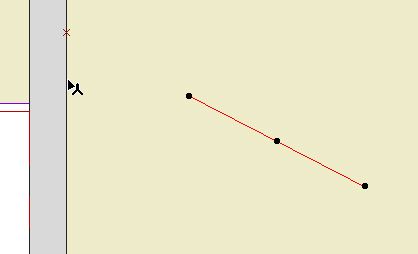
To place a spot like this, select the line, activate any tool except the line or arrow tools, and Cmd+click on the wall.
If the arrow tool was active, nothing would happen. (I think this is a bug.) If the line tool was active, the line would extend to the wall. (Cmd+click acts like adjust where the active tool matches the selected element.)
In most cases, I would just extend the line.
A truly, I think, useless feature crops up when you Cmd+click on a roof edge instead of a corner, when trying to find the height of a roof at a point. You get a hotspot at both corners bounding the clicked edge. And you don't get the height box, which should tell you you're doing something wrong.
While hotspots are usually low-utility in modeling, they are almost required in laying out sheets. Hotspots are visible and detectable in drawings placed in layouts. They cannot be printed. When placing alignment hotspots, use a prints-black pen (I like 5), so you see them against the white of the layout area and the grey of the rest of the window. Some applications:
Update for AC10: I'm leaving these in for now, but these techniques are generally obsolete in AC10. In 10, everything in a drawing is detectable, just like you're looking at the model directly. Many drawing alignment issues can be handled directly now. (Plan alignment in 10 here.)
• Hotspots at the corners of the drawing area in the plan window, for aligning the plans on the sheets. Since all the plans will use them, they should be on the Archicad layer. The templates have drawing area objects and hotspots for each sheet size. You'll probably need to move them to frame your project correctly. Though the object shows on all stories, the spots need to moved on each story. Alternately, you can move one group and copy it to the other stories, deleting the old ones. These spots should be grouped and locked. In PM, you may have to resize the drawing frame to fit these spots.
• The drawing area matches the available layout area within the title block. There should be hotspots in the title block at the four corners of the big empty space. There should also be spots at the center of the sheet number box, and the left edge of the (optional) sheet title box. In the templates this is done.
• Use hotspots to align drawings as they are aligned in the building, such as two wall sections next to each other, or parts of the same wall section. Place hotspots on a common point of both drawings, such as a wall or floor plane, then drag the drawings in PM to align the spots.
• Switch the title block to the RND9 version. Required. Use Cmd+Opt+click on the new object to retain settings. This is very important. If it fails, that is, you get the new object with default settings, cancel out of the settings box and try again. Delete all the hotspots. Place new hotspots in the sheet number box and the corners of the main drawing area.
• The grays as they come out of the new plotter are all darker. This affects the gray poche in the walls, etc. and the gray lines we use for floor and material fills.
The poche is a little dark, but we can live with it. If you change it it will look better, but it's a chore: You must change the fill background color of all 3D building elements (walls, roofs, slabs), and the background color of all the skins in composites whose settings are used in elements, and the fill color/background color of any masking fills, and the fill color/background color of any objects that show poche in plan or section, keeping in mind that some of them have special parameters for these fills. A chore. If you choose to go through with it, use pen 50. This is our new, dedicated poche pen. The idea is to make the next gray revision simpler; with a dedicated pen, we can just change the color of it rather than the settings of dozens of elements. I wish I'd thought of it sooner. So, poche pen change: Optional.
The fills, however, aren't quite OK. They should be changed to pen 150*. Strongly recommended. The fills include:
1. Fill elements, many of which will be on the F Floor Fin2 layer. Use find and select, on each story, for fills with pen 93.
2. Cover fills on 3D elements, including slabs, roofs, meshes. Do this in the 3D window to get all the stories at once.
3. Vectorial hatching pen on materials. You have to do each material separately in Options -> Attributes -> Materials. (Attribute Manager doesn't work for this.)
• In addition to the grays being darker, all the line weights are heavier, so we need to make all our pens slightly thinner. You will have to do this by hand in PlotMaker. In Archicad, you can use Attribute Manager to import the pens from 3 Resources : Attributes : Color Pens 0105. Required.
All the changes discussed above will be made in the templates.
*UPDATE: This used to say 92. 92 is the right color for plotted output, but in Archicad it looks too light on the screen. Read this post about the new material fill pen. As for changing the pen, either 92 or 150 will work in PM.
One more change resulting from the new plotter: To go along with the dedicated poche pen, 50, we have a dedicated Material fill pen, 150. On the same principle as the poche pen, this gives us specialized control over the material fill color without changing a lot of settings.
I thought 150 and 50 kind of went together.
The pen is set to print in PM with the color of pen 92 (90% Grey), and display in Archicad with the color of pen 93 (80% Grey). The weight is 0.15mm, the same as 92, 93, and the rest of the <50% greys.
This pen is intended for vectorial hatching on materials, cover fills representing materials, and fill elements representing materials, such as floor finishes.
The templates have been updated. To use this pen in current projects, you must:
• Change the color and weight of the pen in PM (Options -> All Pens And Colors) and Archicad (Options -> Attributes -> Pens And Colors).
• Change the Vectorial hatching pen of the materials.
• Change the fill pattern pen of elements with cover fills.
• Change the pattern pen of floor-finish-type fills.
Remember: With the new plotter, 93 is really too dark for these fills. You should change the pen. If you've already changed a project to use 92, changing to 150 is optional. If you haven't changed yet, use 150.
There is a bugfix, they call it a Hotfix, I don't know what that means, update to Archicad. The updater is on the Onion in Archicad Program Files. It's called AC9-1965.
Everyone should run this. You can run it from the Onion, rather than copying it to your machine.
(You can check for updates any time by choosing Check For Updates from the Help menu in Archicad.)
Here is the list of fixes. Most of them don't mean much to me, hopefully some of our (unlisted) issues have been fixed too.
It has been out for several days and no one has complained yet, so it probably does no harm.
Graphisoft's version numbering scheme has become completely ridiculous. Patches like this one should increment the third digit in the version number, making this 9.0.1. But no, they have this quirky "v1, v2" patch numbering deal, but they don't even use that consistently. Sometimes a patch increments the v number, sometimes it adds a "+", and in this case it does nothing, it's still v1. So it's not 9.0.1, it's not 9.0.0 v2, it's not 9.0.0 v1+, it's 9.0.0 v1 Build 1965. You have to know the build number, which should be a really geeky arcane thing, in order to describe the standard current release of the program. Most people outside of software development don't know what a build number is. Ridiculous.
All Entries | 1 | 2 | Older »