On Land

Environment Information
At Rill Architects we run ArchiCAD on macOS. If you work at Rill, this is your stuff. If you don't, but you work in ArchiCAD, you may find something interesting. Anybody else, I don't know.
RSS
Tools Archive
Alignment chart

I didn't want to talk this to death. What I like about alignment charts is they are assertive rather than argumentative. You have to just look at them and work out the relationships among the things, and ask yourself if your impressions of the things agree with the author's.

I made this by instinct. The strongest notion I had was that the morph tool is chaotic evil. The second strongest notion was that the mesh tool is a relic and needs to be done over. Then I was on my way.

Having meditated on it a bit, I think this is what the axes mean:

The lawful-chaotic axis runs from standard orderly content to custom content. The good-evil axis runs from user flexibility to user frustration. With that, I will proceed to talk it to death with some comments on each item.

More»

With an assist from Brian Spears and Link Ellis, I figured out that one of my wishes for the mesh tool is already solved. So I thought I would take the opportunity to revise this overview of the tool.

The most prominent use for the mesh is site modeling. I cover that in more detail in another post, but you need the mesh basics first.

More»

Some are redundant. I will probably think of more.

• Use the 'Working Dims Plan' Layer combination.
• Option+click on existing strings to maintain witness line justification as you move in.
• To add one string's ticks to another, select the string to keep and Cmd+click on the string with the points to add.
• Use the arbitrary angle setting when dimensioning walls, for auto-orientation.
• Use the 'place, rotate, drop' construction method with the CL object.
• To graphically justify a group of witness lines: Select the ticks. With the dimension tool, click on the segment and drag it to the desired justification point. Useful for backing up a few witness lines where the plan is very near.
• When you select a tick, the element the tick is connected to will briefly show as selected. To maintain this effect long enough to actually observe it, hold the mouse button down on the tick.
• Ticks can accumulate at a single point. If you try to delete a tick and it stays put, keep trying.

See also:
Dimensioning, General Principles

Zones are information elements. They represent rooms and other definable areas and volumes in the project. You don't need them to build a good model, and you don't need them to create good drawings. They make the project smarter by letting you treat a space as a thing, so you can keep track of information associated with rooms as opposed to their enclosing elements.

Zones' responsibilities can include:

• Displaying the room name and number in the plan
• Reporting room dimensions such as area and volume
• Holding on to descriptive data for use in a room finish schedule
• Automatically naming interior elevations
• Giving locations for a fixture schedule

More»

The interior elevation tool is like a compound elevation tool geared towards presenting rooms rather than whole buildings. It creates a group of sub-viewpoints within a header viewpoint. The header viewpoint is a polygon, which is, in turn, generally associated with a room. Each edge of the polygon shows one wall of the room, in its own window. IEs can be made aware of zones such that they fit themselves to the zone height and automatically name the viewpoints after the zone. The polygon can be complex, though that makes the markers tricky, and they can be a single line/wall.

IEs have some frustrating and obvious limitations, extra-frustrating for being so obvious, but I think you can be productive with them. Sometimes. So a lot of this is workarounds, some more successful than others.

More»

Rectangle Profile
Pretty tricky
This is so trivial/obvious that I hesitate to point it out.

You can't rotate a conventional beam element about the long axis. (Why? Dunno.) But you can rotate profile beams. So you just need a rectangular profile.

But if it's so obvious, why isn't there such a profile in the default templates, among the faux-proof-of-concept distorted steel shapes? And why wasn't there one in our templates until yesterday? Dunno that either.

See also: AC Reference Guide pg. 242

A skylight is like a window for a roof. It's an object which has the ability to cut a hole in a roof.

The AC library contains several skylights at Object Library 9/07 Therm and Moist Prot/Dormers and Skylights.

I haven't made any literal skylights, so if you need one use the AC library.

Why am I telling you about this now. Like windows and doors, the primary function of the tool is to place building elements of those types, but there's other generic uses for the hole-cutting functionality. Such as the Trim Panel window, which is a pretty poor window from a light-and-ventilation standpoint.

So my first skylight isn't a skylight, it's a trim panel. More on this soon; I wanted to discuss the tool in a general way first.

Placement Like windows have to be in a wall, skylights have to be in a roof. To place a skylight, set up the skylight tool and click over a roof.

OK, full disclosure, they don't have to be in a roof. If you place it outside a roof, you will get a warning, but the object will be created. If you move the skylight over a roof, it will become linked to that roof. The real meaning of the warning is that the skylight isn't linked to any roof, which pretty well defeats the purpose.

You will also be warned if the skylight overlaps an edge or a hole, including another skylight. Touching an edge is OK.

The skylight automatically orients itself along the slope direction, and tilts to match the slope angle. If the slope changes, the skylight adjusts itself. If you rotate or mirror the roof, the skylight follows. If you copy the roof, the skylights are copied too. If you rotate the skylight, well, you can't; it will re-align itself.

The Hole Roof holes are not as feature-flexible as wall holes. Hopefully future versions will be better. Hey, they're better than slab holes, which are in heaven waiting to be born.

Skylight holes are always rectangular. There are round, etc., skylights in the AC library, but they cut rectangular holes, and the object fills in around the round part with roof-matching material. Trouble is, there's no way to not-draw the edge of the hole; the lines are there no matter what the skylight does. The current GDL doesn't offer a way around this.

The roof hole is cut with particular edge angles. The sides are vertical (fine by me), the top is horizontal, the bottom is vertical. You can select the roof or the hole and edit the edge angle normally. Trouble is, if there is any change in the skylight, the hole is regenerated from scratch and those default angles come back. And I mean any change, even a pen. Dragging it, stretching it too. If you change the roof slope, the skylight is regenerated, and the angles revert. If you copy a skylight, the new one will have default angles.

If those angles work for a given application, then good. But for the trim panel, we want perpendicular angles top and bottom, permanently. Again, GDL does not currently provide a way to control this. It can be quite frustrating.

Layers Unlike doors and windows, skylights have their own layer. The roof can be hidden, and the skylight show. This is mostly for the good, but there is a side effect: If you select the roof and go to 3D, you don't see the skylights. If you select the skylight, you don't see the roof. (Where with doors and windows you get the opening and the wall either way.) Also, if you hide the skylight's layer, you still have a hole.

A typical skylight-type skylight should probably go on the same layer as the roof. The trim panel skylight can be handled as trim; if you want to see it in RCP, use the layer F Trim Crown.

You can think of polylines as 1) lines and arcs joined together in one element, or 2) Fill elements that don't need to be closed and have no hatch pattern.

The benefit of polylines over lines and arcs isn't really in the initial placement, it's in editing going forward. The polyline can be selected and manipulated as one element. You can edit a chain of lines as a polyline, but first you need to select them all, so they should be grouped, so you need to turn groups on to select them, and then off to do the editing. Cumbersome.

I use polylines for elevation outlining, roof overhang dashing, and wall-section-window-cut-edge heavying, and other things that slip my mind.

You can join lines, arcs, and polylines into a single polyline using the Unify command (Cmd+U). So you can convert to using polylines at any time.

You can add nodes to the end of a polyline using a pet palette button. You can't add curves in one step, you have to add a straight segment and then curve it. You can't do boolean add or subtract with polylines since they don't have area. This is logical but sometimes annoying.

With Gravity on, you can placed associated Level (Z-elevation) Dimensions on slabs, roofs, and meshes.


This guy.

(As with regular dimensions, the text can be customized, breaking the association. I use these on reflected ceiling plans, since you can't get gravity to detect the bottom of an element. A wish. (There might be a way to use a label for this, but I haven't tried.))

You should use associated Level Dimensions to show all the surface elevations in the project. Here's the slab stepping down in a theater:


You can also put grade elevations on a site mesh. Here I used the house outline as a guide to show the elevations at the corners. I don't know whether we should actually do this, but it sure is easy. (Also, there should be a way to display sea level, but I can't find it.)

UPDATE: To show sea level, assuming you have it set properly in Working Units and Levels: After placing the dim, select the text. In the Info Box, click the flyout at Measured Value and choose Autotext. click the flyout to the right in the same tile and choose "to sea level". I didn't bother updating the picture, so you'll have to take my word for it.


To place an associated Level Dimension, activate the tool and turn gravity on for the desired target, by clicking the slab, roof, or mesh gravity button. Then just click on what you want to dimension.

If the dimension value is wrong, it's because gravity detected the wrong element. For example, you're trying to get the main floor deck elevation and gravity is finding the ceiling. Hide the layer of the element that's in the way.

Tip: If you select the Level Dim and hold the mouse button down, you can see what element it's associated with. (This works for regular dimension ticks too.) This helps you track down elements in the way. Select the interloper, then use the Quick Layers palette to hide its layer.

Hotspots do two things:

1. Placing a detectable point where there isn't one.

2. Making a point detectable in PlotMaker, for the purpose of aligning drawings to one another or to the layout.

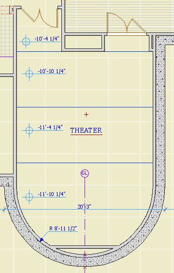
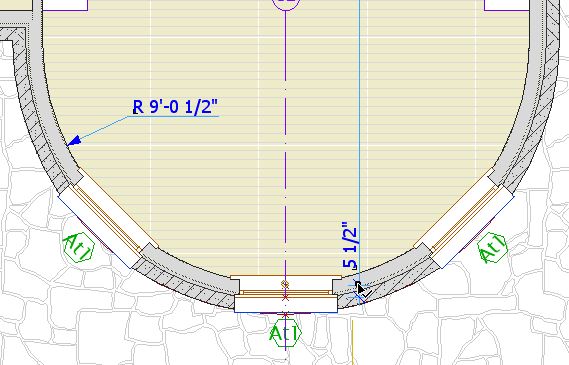
In practice, I use very few hotspots. I try only to use them where they will be permanent. A common example is a hotspot at the maximum of a curved wall, so the wall can be dimensioned.


Such permanent hotspots should be locked.

I almost never use them as a workaround, and if I do, I delete them immediately. If you get in the habit of placing a lot of hotspots and leaving them around, the workspace becomes cluttered with extra detectable points, making it harder to be sure you are detecting the point you want, leading to errors.

Further, hotspotting an arbitrary point to detect it is usually not needed. Special snap points and the ghost story make it possible to detect any point worth detecting, and you can move the origin to "transmit" a point through stories. You can also use CenterPoint JAM9 as a hotspot, and it has the added benefit of showing on multiple stories. And really, how often do you need to detect a point that's truly in the middle of nowhere?

If you've gone on a hotspot binge for whatever reason, you can delete them all at once: Activate the tool, Select All (Cmd+A), delete. Since your permanent hotspots are locked, the won't be harmed in the purge.

Hotspots are also created by certain variants of command clicking. This has occasional usefulness, but it more often happens by accident. Be aware of it so you don't wonder how you made a hotspot without the hotspot tool.

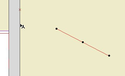
The hotspot on the wall is in line with the red line:


To place a spot like this, select the line, activate any tool except the line or arrow tools, and Cmd+click on the wall.

If the arrow tool was active, nothing would happen. (I think this is a bug.) If the line tool was active, the line would extend to the wall. (Cmd+click acts like adjust where the active tool matches the selected element.)

In most cases, I would just extend the line.

A truly, I think, useless feature crops up when you Cmd+click on a roof edge instead of a corner, when trying to find the height of a roof at a point. You get a hotspot at both corners bounding the clicked edge. And you don't get the height box, which should tell you you're doing something wrong.

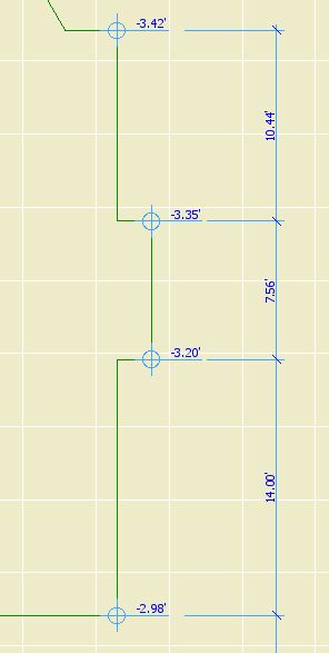
While hotspots are usually low-utility in modeling, they are almost required in laying out sheets. Hotspots are visible and detectable in drawings placed in layouts. They cannot be printed. When placing alignment hotspots, use a prints-black pen (I like 5), so you see them against the white of the layout area and the grey of the rest of the window. Some applications:

Update for AC10: I'm leaving these in for now, but these techniques are generally obsolete in AC10. In 10, everything in a drawing is detectable, just like you're looking at the model directly. Many drawing alignment issues can be handled directly now. (Plan alignment in 10 here.)

• Hotspots at the corners of the drawing area in the plan window, for aligning the plans on the sheets. Since all the plans will use them, they should be on the Archicad layer. The templates have drawing area objects and hotspots for each sheet size. You'll probably need to move them to frame your project correctly. Though the object shows on all stories, the spots need to moved on each story. Alternately, you can move one group and copy it to the other stories, deleting the old ones. These spots should be grouped and locked. In PM, you may have to resize the drawing frame to fit these spots.

• The drawing area matches the available layout area within the title block. There should be hotspots in the title block at the four corners of the big empty space. There should also be spots at the center of the sheet number box, and the left edge of the (optional) sheet title box. In the templates this is done.

• Use hotspots to align drawings as they are aligned in the building, such as two wall sections next to each other, or parts of the same wall section. Place hotspots on a common point of both drawings, such as a wall or floor plane, then drag the drawings in PM to align the spots.

"Labels are text blocks or symbols optionally linked to construction elements and 2D fills. Labels allow you to identify or comment elements or parts of your design." That's from the Archicad 9 Ref Guide page 343, and it's pretty succinct so I'll keep it. Here's more:

"You can use labels in two ways:

Independent labels manually placed using the Label tool.

Associative labels can be assigned automatically before the creation of an element or added to them later."

So there's two kinds. Independent labels are like regular objects, in that they do their own thing. There is a simple text label that's basically a text block with a leader, and it works OK as long as you don't go longer than one line. I (used to!) use these to call out structure in the sections and other simple things like that. They are a marginal improvement over plain text with an arc.

Associative labels are attached to elements, and can say intelligent things about them. They remain accurate as the data they represent changes. They can move when the element is moved. They are very cool.

(Why don't we use them yet? Because the underlying design of the label functionality is very poor, making it hard to figure out how they work, especially the differences between the two kinds. Now that I/we have them figured out, the actual making isn't hard.)

Frequently (Probably) Asked Questions follow. I'm focusing on associated labels, since independent labels are simple.

More»

You can't place a detail marker in a detail window. Rats.

You can change the linked drawing of a placed marker by opening the settings and clicking 'Browse' underneath the detail name.

I've updated the other post with this info.