On Land

Environment Information
At Rill Architects we run ArchiCAD on macOS. If you work at Rill, this is your stuff. If you don't, but you work in ArchiCAD, you may find something interesting. Anybody else, I don't know.
RSS
GDL Archive

This object builds a model of any pen set in the project. Yes, a model. There is a block for each pen, which is the color of the pen, and the height of the block is the width of the pen enlarged from mm to meters.

Pen Sets Model

There is no REQUEST for pen set data in GDL. So to get the pen set data, we need to export it to XML from Attribute Manager.

Then we run a series of regex find/replace operations in BBEdit, using an Automator application. This strips out all the XML formatting, leaving only the pen set data, and then adds some GDL code.

These are the regex operations:

  1. Strips tabs
  2. Replaces empty description tag with <Description></Description> for symmetry with non-empty descriptions
  3. Reformats width but I don't see the effect; must be for special cases
  4. Reformats each pen block into one line of #, width, RGB
  5. Replaces "1," at the beginning of each pen set with "PUT 1,"
  6. Deletes other attribute types
  7. Deletes header stuff before the first PenTable
  8. Converts PenTable tag to ID and name, code to put ID and name into arrays
  9. Puts pen #, width, RGB into PenData array, after pen 255
  10. Deletes all closing tags

As you can see, I can't remember why we need step 3, but I was afraid to remove it.

Just for fun, here is the search string for step 8:

<PenTable Idx=".*" Name=".*">\n<OdbObj Mv=".*" Sv=".*">\n<OdbRef>\n<guid>.*</guid>\n</OdbRef>\n<CreaTime>.*</CreaTime>\n<ModiTime>.*</ModiTime>\n</OdbObj>\n<Name>(.*)</Name>\n<Index>(\d*)</Index>\n<Flags/>\n<ModiTime>.*</ModiTime>\n<RegMemoTable MemoNumber=".*" Mv=".*" Sv=".*"/>\n<ReadOnly>.*</ReadOnly>\n<Pens>

These get replaced with this:

IDseed = IDseed + 1\rsetID = \2 \rsetIDs[IDseed] = setID\rsetNames[IDseed] = `\1`

The resulting text, which is bunch of PUT statements and arrays being filled, is copy/pasted into the Master Script of the template model object.

So now we have an object that knows the name of every pen set, and the weight and RGB of every pen in each one.

The names go into a VALUES{2} parameter list so the user can choose the pen set by name. I'm sorry they're not in alphabetical order; I could probably fix that.

Pen Sets Model

The 3D script builds a matrix of blocks, each one with a custom material defined by the RGB of the pen.

The 2D is just a PROJECT2, making this, it just has to be, the most computationally intensive 2D pen table object anywhere.

You can graphically select the pen set using the slider marked with a plus sign at the bottom of the table.

Note: The object ignores the current model pen set. The colors and weights only come from the pasted data.

Requirements

Archicad 23 or 24
A Mac
BBEdit
Free Time

Instructions

In Attribute Manager, select all of the pen sets and copy them to the right by index. Export the XML attributes file. Drag the XML onto the Pen Data application icon. BBEdit will launch if it is not running, and the converted XML text will be presented in the front window, as well as copied to the clipboard.

Open the object and open its master script. Delete the sample text from between the two lines of asterisks. Paste the converted text here. Do a save as on the object. Place the object in the project. The pen set can be selected in settings, or by sliding the control at the bottom of the table.

Another idea: Graphically editing the weight of the pens via the height of the blocks, then rebuilding the XML file through crazy string operations, so we could import it back into Attribute Manager. This is not implemented at this time.

Download

Here's a general solution to dashed lines in 3D. Line types aren't available in 3D GDL. I'm using this for hinge lines on doors and windows.

Dashed Line 3D

More»

Location: 32 Exterior Improvements /

Update: Japan and Alaska.

I needed a US flag, and I didn't have my own, so I searched in the settings dialog. The US Archicad Library doesn't have one either. There is one on BIMComponents, written by Graphisoft, and maybe that one is in the international version library. It's just as well, because the object (Flag.gsm) doesn't offer the US design.

In fact, it doesn't name any countries. It is charmingly purely parametric: Choose the number of stripes, their direction, and their surfaces. In this way, they can cover lots of the flags of Europe. There is also a cross option to address Scandinavia. UK? Haha no.

This Graphisoft flag looks really good. It is waving, compound waving even, and it droops just a bit. The code is classic morphbarf, though I wouldn't know how to create such a morph in native Archicad. It was likely done in a proper freeform modeler, imported to a morph, and then saved as an object. Their trick is to slice up the waving flag geometry with CUTPLANEs in various proportions and directions, depending on those non-national parameters, and then apply colors to the slices. So Hungary and France and everyone have different stripes with the exact same waving.

But now we can see why there is no US, UK, or Canada version. The stripes and crosses are all simple straight cuts, and sometimes flags need closed and nested polygons, many of them. When I have to weave together a lot of weird geometry, I head for the group operations, the GDL equivalent of SEOs.

I appropriated the morphbarf and abandoned the rest. (The license on Flag.gsm is Attribution-No Derivatives, but the editor offers limited choices - seems like ShareAlike would be better. Graphisoft please get in touch if you have any concerns.) The operations used are subtraction (SUBGROUP) and intersection (ISECTGROUP). The flag parts' geometries are made via PRISM_, and the trick there is to slope them down to match the droop of the morph. (Tip: (-1) * SIN(droopAngle) * horizontalDistance) Some shapes are subtracted from others, such as the stars in the blue fields. Then each finalized PRISM_ is intersected with the morph geometry, which creates chunks of waving stuff with the different colors.

flags

The leaf translation required some thinking, but I developed a general method that should come in handy again.

In exchange for the morphbarf I am happy to offer the finial and the tapered pole.

As of this writing I have the US (needed), Texas (so simple, and someone might need it), Puerto Rico (requested), and Canada (who doesn't like Canada). Next is probably DC (easy, local) and Alaska (I just like that one). Japan? Having done the maple leaf, I can see the UK from here, which would lead to AUS and NZ. Anything with a fancy seal or heraldry (Mexico, half the US states) will require different techniques. Staying away from Maryland for now.

Download here.

Happy anniversary to this post from October 16, 2006. That's the year of Archicad 10.

The post is called Ways Objects Have to Be Right. (I should have said library parts, I regret the error.) There were a lot back then:

  • Plan symbol
  • Plan symbol on remote stories
  • 3D hidden line
  • 3D shaded
  • 3D render
  • Elevation
  • Elevation in distant area
  • Section
  • Polygon efficiency
  • Scale sensitivity; which compounds the plan symbol, section, and polygon issues
  • Listing
  • Labeling
  • User interface
  • Parameter list
  • Parameter transfer management (Unique parameters)
  • 2D graphical editing
  • 3D graphical editing
  • Selectability
  • Code maintainability
  • Intra-library consistency

And that's still most of them. The user interface options have become more complex, and the new rigor around using certain global variables in the parameter script has been disruptive, but most of my day to day concerns are on the old list.

At the time I noted that the GDL editing environment ignores a lot of well-established GDL features:

The development environment gives very poor support for many of these requirements. As Archicad adds features, items are added to this list. Irritatingly, the environment has not kept up, and is way overdue for a tear-down. There is no section window, no remote stories, no graphical editing. The full features of the current GDL architecture are not supported, so we can't even imagine modern development features such as syntax coloring and auto-completion.

To that I would add: Cutting, wallhole (and later wallhole2) and solid geometry operations.

Ten years later, the GDL environment is practically unchanged. Not entirely: You can create a new parameter in the middle of the list, and you can search for a parameter name. They ironically gave the hide parameter button a red 'X' for version 20. I'm grateful for two of those and neutral on the third.

But every one of those unsupported features is still unsupported. You still can't Cmd+G to Find Next. The error messages are still deliberately vague. (How many parameters too few, or too many? Which !@#$% variable wasn't initialized?!) Check script still lights up random macro calls, so you have to check again, note the line number, and navigate there yourself.

Frustrating neglect reached a new peak with Archicad 19, as the new tab interface (tabs are great!) couldn't remember that GDL windows should be undocked, always, and no one who had actually worked in GDL would dream otherwise. Archicad 20 is an improvement - The windows stay undocked, but they don't remember their positions and stack order well at all, so there is still a lot of inefficient UI overhead.

When I wrote that post ten years ago, I think I thought there might be a GDL editor section window someday, or that you could see cutting geometry in wireframe. The verdict of history is clear!

I still think GDL is one of the most important features in all of Archicad, and I think it had the potential to be a key technology for custom content in the larger BIM world, though that horse is long out of the barn. No serious developer of anything works with such poor support. At this point, GDL is valuable to our work so I work with it a lot, unable to forget that it's an abandoned 20th century artifact.

This is the 9-years-bugging-me thing from a couple days ago.

I have used doors and windows of my own making since Archicad 8. When I started, it seemed essential to getting our projects looking the way we want; the Archicad Library items just didn't do the job. I know they have improved over the years, but I don't know how much, because I don't use them. I'm sure they are better in many ways than mine, being more full-service, but that's the thing: Mine do exactly what I want, and they don't do other things. When I need a feature, rather than wishing for it, I add it. This is the still-underrated power of GDL.

I'm not saying you should develop your own doors and windows, you likely shouldn't. But having started, I continue. My libraries work well, and I don't pay much attention to changes in that part of the Archicad library. But in AC17, Graphisoft made quite a big change in the behavior of the opening tools themselves, which exposed what was previously an inconsequential limitation in my doors and windows.

One of the things I decided very early on to ignore is the "Flip" button in door and window settings. If you're using my library parts, you don't use this switch. You rotate and/or mirror the element. In our practice, which is US residential mostly wood framing, the flip switch doesn't offer any advantage.

Bad flip
So, my doors and windows aren't designed to work with the flip switch, and if you "Flip" them, you will immediately see that you should "Flip" them back. Installing doors so they are entirely outside the wall is not sound practice!

I always sort of wondered why this was, but it was never a priority because I don't use the feature and don't feel compelled to start.

Bad door placement

But in AC17, the new UI of placing openings essentially allows you to place the opening flipped, which leads to a confusing user experience if the library parts don't support flipping. So I finally took the few minutes required to get to the bottom of it. (Search for "flip" in GDL manual, Google "WIDO_FRAME_THICKNESS", read this Archicadwiki article, at least that part of it.)

Simply put, when the flip switch is activated, the door or window is mirrored across the "reveal side" face, and shifted by the "nominal frame width", which is a special value in the compatibility options of the details tab. This value can be a length or a GDL expression that uses parameters. It is zero by default, so the shift that should follow the mirroring doesn't take place. I don't use the built in "reveals" (they are also on the ignored feature list), so for my doors and windows this value is just the wall thickness (global variable WALL_THICKNESS, though I still prefer the old name C_).

Nominal frame thickness

I'm still not flipping my doors and windows, but now they don't look ridiculous when placing them in AC17.

There is one case where this info might matter to users that doesn't have their own libraries: When saving a custom, slabified opening from the 3D window. When you place that part in AC17, you will get the confusing flipping behavior unless you set the nominal frame thickness to WALL_THICKNESS, or to the dimension of an actual frame component, if appropriate. It just shouldn't be zero. It would be nice if the saving process for those parts did this automatically.

I also don't like that they use a sun icon to represent the reveal side as if the reveal side were always outside, but that is another topic.


Library Globals were introduced in Archicad 13. But I only noticed them after jumping to 16, and by that time there were enough examples in the wild to make their value clear. They have enormous potential, especially compared to their relative ease of use, if you are already a GDL/library/standards person.

In GDL there are Global variables, which make information about the project available to library parts. Some globals contain environment information like the current scale, the north direction, or the current viewpoint (window) type. Others are element-specific, so doors and windows can behave intelligently within their walls, for example. Labels can use globals to automatically display information about elements.

Globals are just there, waiting for you to mention them. The global for the current scale is GLOB_SCALE, so:

IF GLOB_SCALE <=48 THEN
     [fancymodel]
ELSE
     [simplemodel]
ENDIF

...means at 1/4" scale or larger, make the fancy version, and at smaller scales make the simple one.

In addition there are Requests, which are different in syntax but have a very similar function. A request I use often is "Height_of_style", which tells you how tall a block of text is. Unlike globals, before you can use the information you have to move it into your own variable.

rr=REQUEST("Height_of_style", textStyle, styleHeight)

The parts of that line are, in order:

rr is a variable to hold the return value of the request, which is not the data we are requesting. Instead it reports if the request was "successful". You can leave it out and the request will still work, but you will get an error. "rr" is my personal preference; it can be "n" or "success" or whatever.

REQUEST("Height_of_style" is the name of the request.

"textStyle" is my previously defined style in the script. You need at least one style defined to do anything with text.

"styleHeight" is my variable to hold the data about the height, which is what we are looking for. Now I can do stuff with that value, like draw a line as long as a text element is tall:

LINE2 0, 0, 0, styleHeight

Other requests can look up the current dimension preferences, the state of model view options, etc., etc. There's a complete list in the GDL manual.

I'm hazy on what makes a bit of information a global or a request. (Why is the layer a global, but the zone category a request?) Anyway, both kinds of things are defined internally by the program, and that was all there was, until Library Globals.

Library Globals allow library developers to create their own model view options.

Let's say I want the steel column objects to display differently in the framing plans and the architectural plans. In vanilla Archicad, that's not a model view option. With doors and windows, I can control whether the openings, symbols, and markers are shown, and then save those settings with the views for different plan types. Not so with the steel columns. I could have a setting in the object to change the appearance, but it's the user's job to switch it back and forth. (Tip: Any workflow with the phrase "user's job to switch it back and forth" is not an optimized workflow.)

With Library Globals, I can create a setting in model view options to change the appearance. I can have the objects respond to the setting automatically. And finally, I can save the setting with the view.

I can create a setting. I can make the objects respond to it. I can save the setting with the view. Are you getting it? I am excited about the potential of this feature.

There are two parts to it:

1. The Library Globals Settings object. This is a hidden object with the "Library Globals Settings" subtype. Parameters in this object become settings the user can modify in model view options. The interface script of this object provides the interface for those settings within the MVO dialog box.

2. The LIBRARYGLOBAL keyword. This works very much like REQUEST, above.

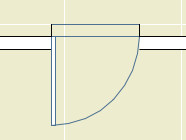
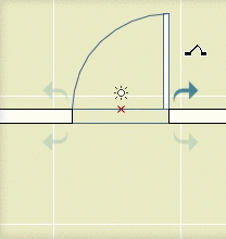
Here is my first application for this feature. I would like to show some structural columns on the story below, dashed, so that in the structure plans you can see that the point loads are being picked up. While I don't mind seeing structural columns in the architectural plans, the dashed-below thing really doesn't work. You get dashed columns in the middle of rooms, which is confusing. So if I want structural columns in the architectural plans I can't show them dashed below in structure plans. And if I want dashed-below columns in structure, I have to turn the columns off in architectural.

What I need is a separate control for display of the dashed-below columns. Library Globals finally provide this.

Again, there are two parts. You need an object with the "Library Globals Settings" subtype. Ours is called "RillLibraryGlobals". You only need one object, even if you are planning settings which affect many different objects. Within the object, I have a parameter with the name "LG_ShowColBelow" (The LG_ prefix reminds me that it's a library global parameter, which clarifies the script on the other end.)

In this simple case, the only script you need in the library globals object is the interface script. This script creates the interface within the Model View Options dialog, where the user will manipulate the setting. Interface script technique is beyond the scope of this post, but the briefest thing that will non-beautifully work looks something like this:

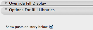
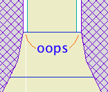
UI_DIALOG 'Options For Rill Libraries', 600, 300
UI_PAGE 1
UI_STYLE 0, 0 ! Small, Normal
     UI_OUTFIELD 'Show posts on story below', 12, 22+5, 148, 22
          UI_INFIELD 'LG_ShowColBelow', 160, 2, 48, 22

Which ends up looking like this in the MVO dialog:

Show columns

That checkbox flips the setting behind the scenes.

The second part is in the object itself, in this case my steel column. The 2D script of the object needs to know about that setting in the library globals object. It's very similar to REQUEST:

!! Library global for column below, show in S, hide in A1
LG_ShowColBelow_val=0 !!initializing
rr=LIBRARYGLOBAL ('RillLibraryGlobals', 'LG_ShowColBelow', LG_ShowColBelow_val)
IF GLOB_CH_STORY_DIST=-1 & LG_ShowColBelow_val=0 THEN END

'RillLibraryGlobals' is the name of the library globals object. 'LG_ShowColBelow' is the name of the library globals parameter being asked about. LG_ShowColBelow_val is a local variable, just initialized, to hold the value found in the library global variable.

The last line says, if we're on the story below the object's home story, and that library global checkbox is off, don't draw anything (END). GLOB_CH_STORY_DIST is the ordinary global variable which says which story we are on relative to the object's home story. One story down is -1.

Then later in the script when it's time to actually draw the column:

IF GLOB_CH_STORY_DIST=-1 & LG_ShowColBelow_val=1 THEN !! story below
     [Draw dashed symbol]
ELSE !! home story
     [Draw solid symbol]
ENDIF

Of course, it's still up to the user to set the object itself to display on the story below. With that set, the MVO checkbox will control the actual display.

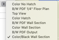
Finally, in the Model View Option combinations, that checkbox is on in the structure plans, and off everywhere else.

We have several objects offer the user a group of roof slope selection parameters. You can select an n/12 slope from the list, or you can enter a custom slope angle. When you select a slope, the angle changes. When you put in an angle, the slope parameter will show n/12 if there is a match, and 'Custom' if not.

I use GLOB_MODPAR_NAME statements to keep such parameters in sync. In the code there are a bunch of IF/THEN statements associating the angles and the named slopes.

Since this lookup is used by several objects, I keep it in a macro and use RETURNED_PARAMETERS to get the data back to the calling object.

More»

Our title block is an object with hard-coded dimensions for each sheet size on our printers. The template has a worksheet for each sheet size, and within each worksheet is placed a title block object set to that size. Then there's a saved view of each worksheet, and the view is placed in each master of a given size.

One object -> A few worksheet views -> Several masters -> Many layouts.

Graphical changes to a given sheet type are made in the master. Changes to all the sheets are made in the worksheet. Changes to every sheet in the office are made in the code of the object. (Rare.) To change every future sheet in the office while leaving extant work alone, you need a new object and you need to update the template(s).

The text information in the title block object is a mixture of autotext tags in <angle brackets> and hard-coded text in quotation marks. The TEXT2 shape commands can use hard-coded text or string variables. Both of these will display the text 'Bar':

!! Display the text in the string variable named foo
foo='Bar'
TEXT2 0, 0, foo

!! Display the literal text 'Bar'
TEXT2 0, 0, 'Bar'

(In this usage, double and single quotation marks (and grave accent marks, on the ~ key) are interchangeable as long as the pairs match.)

Within each script of the object, you need to do a Find (Cmd+F) for all the text bits that need to be changed. If the company name has changed from Foo Architects to Bar Architects, you need to find each instance of 'Foo' and replace it with 'Bar'. Optional: Use the Replace button to find and replace in one go. I usually don't use Replace All unless it's a very straightforward case with a lot of instances. Also note the checkboxes.)

Find & Replace

In the title block object, only the master script and 2D script need to be changed. But while I was in the neighborhood I added some years to the relevant values lists in the parameter script. (Values lists offer the user choices for a given parameter.) I did a Replace All of

'2010', 

with

'2010', '2011', '2012', 

taking care to remember that last comma.

Save as, not Save. Actually, you should save as before you make changes so you don't forget.

More: Structure of Objects, and the Object Editing Environment

Converting 2D elements for use in 3D.

Tree sketch

Any 3D element(s) can be saved as an object with the Save Project As... menu command. (In Archicad 11, Save 3D Model As...) This technique is known as 'slabifying' since such models are often built from slabs. Objects saved in this way are dumb (not parametric), but it's still a useful trick.

2D elements can't be saved this way, because they never appear in the 3D window, where 3D object saving takes place. Despite the fact that GDL contains commands for 'flat' shapes in 3D, including LIN_ (a line) and PLANE (not a joinery implement). But there is a workaround for 'slabifying lines'. When you open a 2D DWG as an object, 2D lines are created as LIN_ statements in the 3D script. When you place the object in the model, you get the 2D geometry in 3D.

It's that simple at it's simplest, but real world applications need some tweaking. In this example, I'm converting an Archicad library 2D tree elevation symbol so I can use it in a sketch render image. Other applications might be a complex ornament in a hidden line elevation, or a busy glazing design placed in front of a conventional window.

More»

AC11 has a model view option to put the floor plan into reflected ceiling mode. It only works for objects, not regular elements (wish wish wish). I have several objects that take advantage of it.

This is the basic code you need to have a symbol draw itself differently in floor plan and RCP mode. The idea is that depending on the state of the switch, you set certain attributes, draw some things and not others, etc. Often, the shapes are the same, but the line switches from dashed to solid; stuff like that.

!! Parameters
!! plnPen : Plan Pen (0=Match)
!! plnLT : Plan Linetype (0=Match)
!! rcpPen : RCP Pen (0=Match)
!! rcpLT : RCP Linetype (0=Match)

!! If attributes are 0, set them to object settings
IF rcpPen=0 THEN rcpPen=L_
IF rcpLT=0 THEN rcpLT=SYMB_LINETYPE
IF plnPen=0 THEN plnPen=L_
IF plnLT=0 THEN plnLT=SYMB_LINETYPE

!! Request state of ceiling switch
rr=REQUEST("floor_plan_option","", storyViewpointType)
!storyViewpointType=1 !! testing

IF storyViewpointType=1 THEN !! ceiling
	!!Set ceiling attributes
	PEN rcpPen
	LINE_TYPE rcpLT
	!! Draw ceiling-only parts
ELSE !! floor plan
	!!Set floor plan attributes
	PEN plnPen
	LINE_TYPE plnLT
	!! Draw floor-plan-only parts
ENDIF

!! Draw parts common to both plans, using whichever attributes
LINE2 ...
RECT2 ...
POLY2 ...

Somebody asked why the flue object can't show a thickness for the flue liner itself.

Flue on Nothing
One reason: The flue sits atop, and lines up with, the top of the smoke chamber object. In section this gives a continuous void. If a thickness is built in to the flue, there would be a discontinuity at the top of the smoke chamber, and the flue would appear to be supported by nothing. Building the flue thickness should help make a better detail, yet this is worse. I could partly solve this by narrowing the top of the smoke chamber, but that doesn't help with the other, bigger, reason.

The other reason: The flue is designed with SEOs in mind. You have to use it as a subtraction operator, or there's no point. It is a simple solid tube (EXTRUDE, actually) which we use to make a simple void. If the flue wall has a thickness, it becomes a solid ring with nothing in the middle.

Flue Filled
When you subtract with a ring, you get a ring-shaped void, with solid, un-subtracted material in the middle. If you cut a section through such a thing, you'll get masonry fill with two stripes of flue-wall fill going through it, and no void.

Flue Air Fake Air
To fix that, I could simulate emptiness within the flue by filling it with solid stuff with a clear section fill. In order to see this stuff and the wall thickness, we would need to make the flue's layer solid instead of wireframe. The problem there is that in a marqueed 3D view, there would be no void.

Well, I could wireframe the layer in building section combinations and make it solid in wall section, and I could make the thickness option scale sensitive in the flue and the smoke chamber, but we're into serious inelegance now. It's a void, except when it's not and it's simulating a void, and it's scale- and layer combination-dependent, and do I 'really' subtract it to 'simulate' a void, I can't remember.

Once again we have met a limit in GDL object technology where the simplest solution is for Graphisoft to give us more power. There is a directive, MODEL, which allows you to build shapes in wireframe or surfaces-only mode in addition to the default, normal, solid mode. MODEL WIRE makes a wireframe shape that looks exactly like switching a layer to wireframe. MODEL SURFACE makes a shape that looks normal from the outside but is hollow. This sounds promising for our problem until we realize that only MODEL SOLID shapes can act as SEO operators.

Therefore, I want a new MODEL option which will make shapes wireframe, but which will allow the shapes to act as operators. So the flue wall would subtract, and the void within the flue would subtract, but the void would still be a void. My first stab at a name is MODEL OPERATOR, but I'm open to suggestions.

An object like the Foundation Drain is trying to offer total geometry and annotation for a particular detail. We want to pack this object with all the data we can think of. The geometry is in good shape, but we're missing the notes calling out all the parts. These will need to be added manually with labels or texts. Since these notes are standardized, they will be written down somewhere; if nowhere else, in the last place you drew the detail. Or in a module, or in a text file. Either way, it's remembering and typing or copy and paste.

How could the notes live in the object? You could script a series of 'labels', with leaders pointing to the detail parts, and editing hotspots to position the texts. I'm skeptical of this. It's sophisticated coding to get an interaction that, to the user, would never be as smooth as moving text elements and drawing arcs and labels. To me, placing the notes isn't the problem, it's remembering/locating the data to write into them.

Here's another idea that would let us keep the notes in the object. Create a switch in the settings to put the whole thing in 'note mode'. Instead of drawing the lines and fills, the object creates a series of text blocks. (These can be multi-line and arbitrarily styled, like text elements, using the TEXTBLOCK and RICHTEXT2 commands.) Then you could copy/explode the object, which would give you text elements you could stretch and arrange as needed.

Unfortunately it doesn't work. When a multi-line text object is exploded, you get multiple single-line text elements. Not helpful.

We need RICHTEXT2 that explodes into a single text element regardless of shape.