All the common layouts (that we can think of) are blocked up in the project templates. These guidelines apply no matter when a layout is first needed.

These instructions are current as of Archicad 20.
With the advent of renovation in Archicad 15, the transition from existing conditions to new construction is much simpler. We still want to finalize and set aside the existing conditions before moving on.
Note: The favorites part of this is different in Archicad 20.
With the advent of renovation in Archicad 15, the transition from existing conditions to new construction is much simpler. We still want to finalize and set aside the existing conditions before moving on.
Updated for Archicad 20.
I encourage you to always use Publisher for all standard printing, PDF, and DWG output. All the pertinent info is stored in the Publisher sets, so you don't have to worry about it: Page setup, printer selection, DWG translation, whatever.
For any Publisher set, you can publish the whole thing or select items and publish only those.
Here are the essential parameters of the four main types of Publisher sets.
What to do when the project is done.
First, make sure it's really done. 'Almost', 'practically', 'pretty much', 'just about', and 'I think it's' done are not the same thing.
In the old days, things were different. How different depends on how old the days are. It's hard to anticipate every issue you might encounter in an old project. The first question is, what do you need from the project? Do you need drawings, a detail, or are we actually resuming work on the project?
Leads and pending projects should be placed in 1 Projects / zPending.
These are projects which have no modeling or design data with them. They might be just a proposal.
When a pending project actually begins, create the project folder as normal. Drag any documents in the pending folder to the new project folder. The proposal belongs in '3 Contract & Correspondence / Proposal'. Trash the project's 'pending' folder.
If a project does not go forward, we will move it to 5 Past Projects as part of our quarterly project cleanup.
All the typical layouts (that I can think of) are blocked up in the project templates. Developing the layouts consists mostly of framing the plan, tuning up the section/elevations, and arranging the drawings on the sheets.
First, to review: The New Construction renovation filter has these settings:
Existing: Override
Demolished: Hide
New: Show
In plan, new walls are gray and existing walls are white. Demolished elements are hidden.
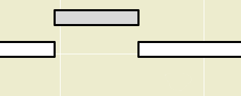
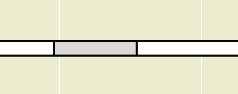
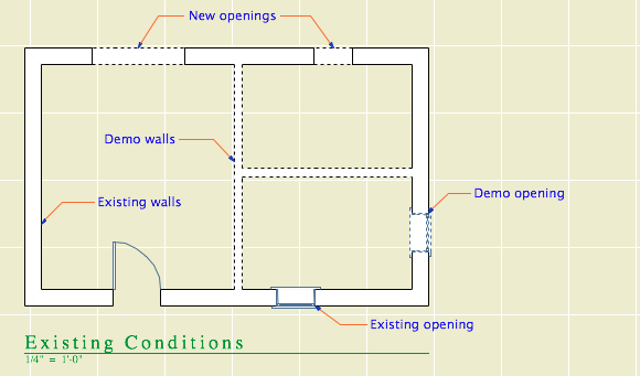
When you demolish an opening in an existing wall, the opening disappears and is replaced by a piece of wall whose status is new.
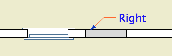
I think this behavior is correct and intuitive. My only quibble is with the lines on either side of the new segment. I'm not convinced the lines should be there at all, and using the cut pen definitely makes them too heavy. But I can overlook it. (Archicad does not consider the difference between element-is-cut and cut-element-meets-air, and I think I have given up waiting for that to change.)
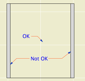
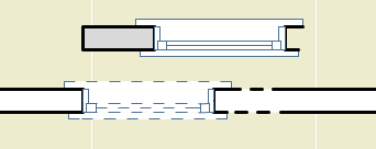
I can't overlook what happens in the elevation. The filled-in portion of wall is explicitly drawn with the shape of the demolished window. There's no way this is OK.
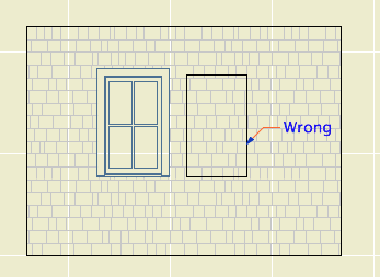
Note: Cut new siding at old window location
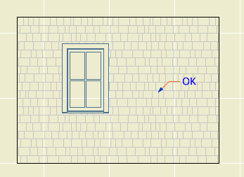
• The new wall fragment is based on the existing wall, so it has the same surfaces. Where elements of the same surface meet, the line should disappear. (This is true in AC17. In 16, the material of both sides of the filler piece matches the edge material of the wall. No words.)
• With the surface cleanup rule in place, they would have to create an exception to it, in the belief that it is conventional to show filled-in windows on elevations. We have never done this.
• If I did want to show this condition, it would be dashed and in a lighter pen. These options are not offered. It has nothing to do with the override styles, even though the override setting is what is causing the rectangle to show. The GDL of the demolished window is not involved. The rectangle is drawn with the outline pen of the wall, making it a heavier line weight than the proper windows on the same elevation. Bad graphic, no user control. It couldn't be wronger.
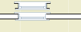
So we need to get rid of it. I stumbled on a way. (N.B.: In the reference guide, there is precisely zero discussion of elevation and hidden line viewpoints in the Renovation section. Once you leave the floor plan you are on your own. Unless you're issuing OpenGL demolition docs, which, um.) In the As Built renovation filter, both existing and new elements are set to show. In the plan, we can't have this because the existing and new look alike. But in the elevation, it means the filled-in wall blends in and there's no rectangle.
Alright! We just need to use that filter for elevations. Maybe change the name so its purpose is clearer. I don't mind workarounds as long as they work, ya know!
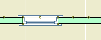
What? Sections? Right, they have cut elements (existing needs to be overridden) and uncut elements (existing needs to match new).
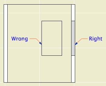
Right like the plan, wrong like the elevation
Good elevation, but we can't tell new from existing
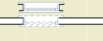
It looks like that filter trick doesn't solve it, and I think we've reached the end of the line. Direct demolition of openings just doesn't work. I don't know how they released this feature in this state, and I don't know how they haven't fixed it three versions later. It's really poor.
We will continue to use renovation. But we have to go back to the old method of splitting the wall on both sides of the opening, demolishing the piece, and filling in manually with a piece of new wall. This works reliably as ever and cleans up in all views.
The logic of renovation is that removing an opening involves creating some wall. When I create a wall to meet another wall and their surfaces match, there is no line. That stupid filled-in chunk should do the same thing.
In situations like this, where a plainly wrong graphic is presented as normal, I get the feeling that Graphisoft's strategy is to hope that conventional documents are swept away very soon by BIMx Docs, live cutting planes, and iPad Pros. My concern for "pens" will seem as quaint as a wax seal! I think they underestimate the status quo bias on the average job site. Today, I need drawings that function in the field. The present is sadly non-futuristic sometimes.
That new world, when it comes, is going to have graphical conventions too, and users will always be charged with turning an ever more complex model into visual information that people can use. At the moment there is a disconnect between the information I can attach to the model ("This window is to be removed"), and the tools to convey that information. ("If this is removed why is it showing?") It should be a core competency of Archicad to bridge that gap.
How to Demolish Openings
First the simple case.
Split the wall at both sides of the opening. The split can be right at the opening's ends, or you can allow some slack.
Drag a copy of the wall with the opening. It's less confusing if you drag it away.
Demolish the opening's wall by switching its renovation status to Demolished. When you demolish a wall, openings in the wall are automatically demolished.
Change the copy's status to New, and delete the opening.
Drag the new wall back in place.
The more complicated case is where a new opening will be placed overlapping the demolished opening. In this situation the pair of walls (demolished and new) must be extended to span both openings, so that the new opening is placed entirely within the new wall.
Placing New Openings in Existing Walls
You do not need to split the wall to place new openings in existing walls. Just place them. The new opening will appear as a demolished portion of wall in the demolition plan. As far as I can tell, there are no graphical problems with using this, the intended technique.
Typically we try to get the existing conditions completed before starting demolition and new construction. It's good practice to save a copy of the PLN at this stage, along with a PDF of the existing plans. But in principle, we should be able to get existing plans out of the project at any stage, and there might be projects where it's not practical to absolutely finish the existing conditions before the design work starts. And this almost works, with some workarounds.
Let's review the basic attribute and renovation filter setup. The natural background color of walls is gray. New walls are gray in output, so the filters are set for new to show; they are never overridden. Existing walls are white in output, so the filters are set for existing to be overridden. Demo elements are white and dashed in output, so they are overridden as well.
In the template, the Existing Conditions filter is set to override the existing elements, turning them white. The demolished elements are set to be shown, but if no elements have been demolished yet that doesn't matter. New elements are hidden, but they don't exist yet. So to publish existing plans at this stage is very simple, because there are no other statuses to account for. Nothing is gray or dashed.
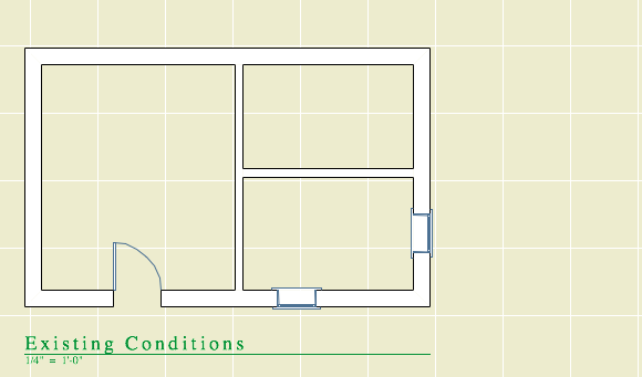
Existing conditions before design work
Once the design work has started, if you want existing plans you need to show the demolished elements. And the filters certainly offer this capability.
Remember that the natural fill color of elements is gray. Existing elements are overridden to turn them white. We'd like to keep that. But we can't override the demolished elements, because we don't want dashed lines.
Existing and demo are overridden, like in demo plans
Instead they are shown, which means the demo walls will be gray.
Existing is overridden, demo is shown
In order to keep the lines solid and turn the fills white, we need to apply a pen set to the drawing element. The poche pen is number 50; all the pen set does is make it white instead of gray. (Yes the screenshot is still of the floor plan. I want them to all look alike. Pen set hacks for output should only be applied to the drawing element, never to to the view.)
Existing is overridden, demo is shown, pen set turns the walls white
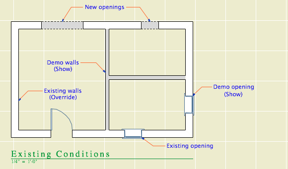
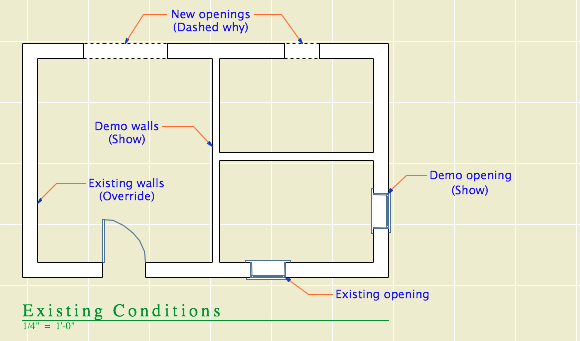
But this doesn't quite solve it. With existing elements overridden and demolished elements showing, you will get a dashed line wherever a new opening is placed in an existing wall. I would call this a bug, because if the demolished elements are showing, you should never see the dashed line because it's part of the override style.
If you set both the existing and demolition to show, then the ("new") openings vanish.
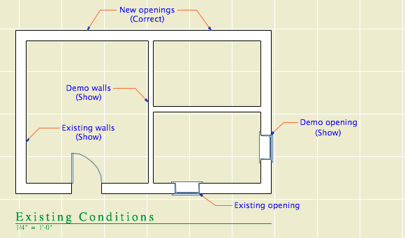
Existing and demo are shown, pen set turns the walls white
The existing plans have the pen set ("Layout Existing Plan") applied to them in the template, though if you publish existing plans before demolition, the pen set isn't needed because the existing elements are overridden to white anyway. The pen set is applied this way just in case.
If you need to publish existing plans after demolition has started, you have to change the Existing Conditions filter so the existing elements are shown instead of overridden. Then both the existing and demo elements are the natural gray color, but both are turned white by the pen set in the drawing.
This is a royal pain! It's hard to figure out, hard to explain, and almost impossible to remember. We have to jump through these hoops because of an incomplete feature compounded by a bug. The incompleteness is the inability to vary the override style by filter. We need to override the demolished elements differently for existing and demolition plans. The bug is the display of demolished elements with overridden attributes even though the filter is set to show.
We are on our third version of Archicad with the Renovation feature. This stuff should be solved by now.
Renovation is a feature set to control the display of existing, new, and demolished elements in the workflow of addition and renovation projects. It began in Archicad 15. This feature means we no longer have three of each layer in addition projects.
In the Renovation workflow, there are three kinds of elements: Existing Elements, Elements to be Demolished, and New Elements. This property is the Renovation Status. With a few unimportant exceptions, all elements have a renovation status, and it cannot be blank.
Renovation Filters control whether and how elements of the three statuses are displayed. Filters are saved with Views.
The filters control whether the elements of each status are Shown, Hidden, or Overridden.
I hope showing and hiding are self-explanatory. If elements are overridden, their appearance is controlled by Renovation Override Styles. The attributes covered by the styles are: Line type; Line pen; Fill type, pen, and background pen; and material. There is no consideration for fill category, so cover and cut fills are handled the same. (Fail.) There is only one set of override styles, and they do not vary by filter. (Another fail.) For example, you can't have one filter where overridden demo elements are dashed, and another where they are dense dashed. Whatever the style of overridden demo elements, that's the style for all filters where Demo is overridden.
Because the override styles are responsible for the appearance of overridden elements, elements of different status will have the same "natural" settings. You don't change the line type or fill color of individual elements to show they are demolished.
The styles are set in the template and should be considered set-and-forget.
There are also Additional Filter Options for existing and demolition elements. Right now the only one of these we are using is to turn off markers for doors and windows.
And, keep an eye on it, it will try to mess with you. The current filter can change by viewpoint; it can be new construction in plan and existing conditions in 3D. When this happens, stuff will "disappear". Check the palette. Once the filter is set for a given viewpoint, it seems to stay put. (Both the default filter and the default status seem to sometimes change spontaneously, especially when opening a project on a different machine.)
The status setting is not transferred by eyedropper/syringe. The default setting on the palette always controls. You can change the status of an element in the settings dialog under Tags and Categories, but the palette is obviously easier and a better habit.
Our Override Styles
New elements are never overridden, and have no override style changes. (N.B. This is our decision, not a design limitation of the new status itself.) New elements act as if the filters don't exist. The background pen is gray (#50), same as it ever was.
Existing: The fill is overridden to be Empty Fill. The fill background pen is overridden to be pen 91 (white).
Demolished: The fill and fill background are overridden like existing, and the line type is overridden to be Dense Dashed.
Again, the natural settings of existing and demolished elements are the same as new. The override style turns them white and/or dashed.
See the appendix at the end of this post for examples of the different kinds of output.
Our Renovation Filters
01 Existing Conditions
Existing: Override
Demolished: Show
New: Hide
This is used for building the existing model, and publishing the existing plans and elevations.
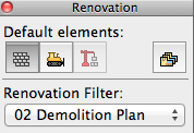
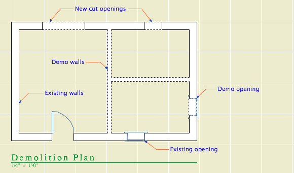
02 Demolition Plans
Existing: Override
Demolished: Override
New: Hide
All the walls have white background, and the demo elements are dashed.
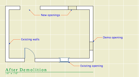
03 After Demolition
Existing: Override
Demolished: Hide
New: Hide
Existing elements only, with the demo elements removed.
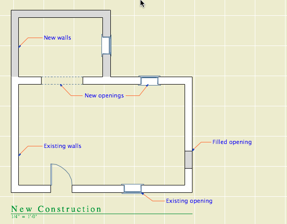
04 New Construction
Existing: Override
Demolished: Hide
New: Show
This is used for most work and output. Existing walls are white, new walls are gray.
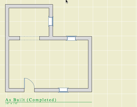
05 As Built
Existing: Show
Demolished: Hide
New: Show
This shows the project when finished, as if it were all new. All the walls are gray.
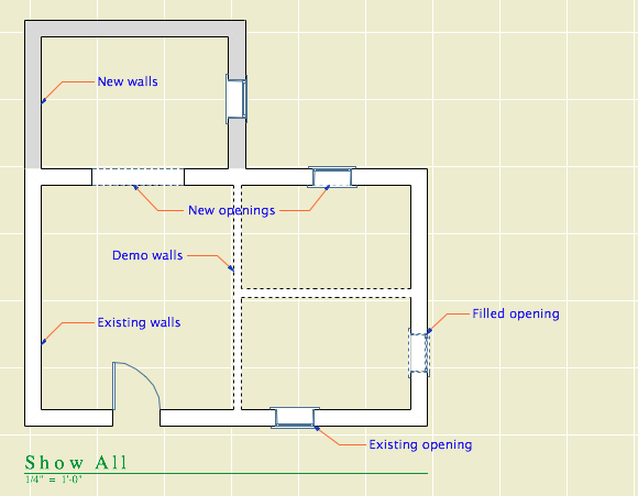
06 Show All
Existing: Override
Demolished: Override
New: Show
All statuses are shown, and you can tell the statuses apart.
How to Demolish Things
Select an element and, on the renovation palette, click the demolished button. That changes its status from Existing to Demolished. Unless the current filter is Demolition Plans or Show All, the element will vanish. If you switch to Demolition Plans, the element will reappear with dashed lines.
Demolishing a wall
That's basically it. Of course, you might have to split an element first to demolish only part of it.
The big difference between the new method of demolition and the old layer-based one is in the handling of doors and windows. Doors and windows are now demolished the same way as other elements. Just select them and change their status. There is no need to split the wall and demolish the piece with the opening in it. When you demolish an opening, it is replaced by a portion of new wall. (Note: That new piece is shown using the natural settings of the existing wall. It's no longer being overridden. That's why all elements have the same natural settings.)
Further, you don't need to split an existing wall to place a new opening. Just place it normally (check the status!), and you will have a new-status opening in an existing-status wall. And in the demolition plan, the new opening location will be shown dashed.
Renovation Filters in New Projects
Unlike layers, renovation filters have only one purpose. (There's not going to be any hacking the demolition status to do something else.) If there's no renovating or demolishing, you don't need them. So in the New Home template they are not used. The filters are in there, but they are modified to show all statuses all the time, with no overrides. All the views are set to Show All. The palette can be put away.
Special Cases Where Multiple Layers Are Still Needed
Even on a New Home project there are some sneaky existing conditions, those pertaining to the site. We have separate layers for existing and new topography contours. We have layers for existing, "demo" and new trees. We have an optional layer for backing up the existing site's mesh.
I don't think these things are what renovation filters are for, and I can't see "using" them throughout a New Home project just to address these tiny parts of the project work. So we ignore the filters, and we have a few oddball E and D layers left. To remove a tree, change its layer and enjoy the nostalgic moment.
Don't Demolish Notes, Silly Rabbit
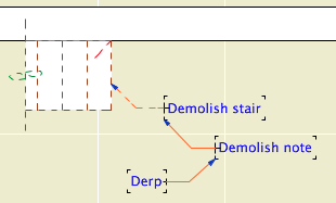
Another layer we didn't delete is +D Demo Note. I have heard of people trying to use one note layer and then make some notes demolition notes by changing their status. This is a category error. Renovation status is for project elements, which represent real things in the world. You're demolishing that note, are you? How? What is the result of demolishing it? Keeping different types of annotation straight is a proper use of layers.
And if we still have the Demo Note layer, we still have the Demo Plan layer combination.
Changes to the Templates
Removed lots of layers.
Implemented renovation filters and override styles.
Applied filters to views.
Updated favorites and default layers.
Created pen set for existing plans.
Secondary Info on Renovation
All element types have a renovation status except hotspots, drawings, figures, and viewpoint-creating tools (Section, etc.).
Elements have a setting in the Tags and Categories division where they can be set to show only on a specific filter, rather than "All Relevant Filters". There's also a button on the renovation palette for this setting. I can't imagine an occasion to use this. That setting is where the warning comes from when you delete a filter: "By deleting a renovation filter, you will lose all elements which are shown only on that specific filter." Since we don't use that setting, we aren't scared of this warning. Further, I don't see the need to delete filters very often.
The filter settings can be imported and exported; they are xml files like Model View Option combinations. (But they import badly, extant filters can't be overwritten.)
There seem to be no GDL globals for renovation status, which seems like a missed opportunity.
This is obsolete as of Archicad 15. From that version onward, renovation is the way. Read this instead.
What happens when the existing model and drawings are done.
The basic idea is to keep the existing conditions, both the PLN and the layout book, tucked away safely. It is theoretically possible to get existing drawings out of the addition project, but it's more trouble than it's worth. It's important that the existing work be complete at this point.
(Heavily revised for AC10, though still a little clunky.) This is the standard workflow for issuing SK drawings.
The templates have a fax transmittal as part of the layout book.
There are three main ways to create views in AC10, plus one more you should never use. The templates have most of the commonly needed views already set up, but it's not unusual to need more.
Update, November 2017, Archicad 21: These screenshots are out of date, but all the principles and operations remain the same.
Every drawing or set we give to someone else should be archived as a PDF in the project folder at 2 Output : PDF Archive. This is for convenience and our own protection.
(Formalization of this.)
If you have a job too large to print in house, email PDF files here.
The files size limit is about 50MB.
Put the job details in the message, including the number of sets, delivery time, and any special instructions.
MBC advises us that you should call them to make sure the job got there and that they are aware of it, especially if the job is a rush, or if you are sending it outside of normal business hours.
(Similar to: In-House Printing (PlotMaker 9))
For large format output we use that enormous, hot, 16-amp-pulling thing in the middle of the office.
(Note: This is about printing layouts. 'Check printing' from AC, for the heck of it, is another matter.)

Publisher automates output processes, including file output. When Publisher saves files, it saves them to the path given in the Publisher set's properties. Under our AC10 workflow, this path should usually be 1 Projects/[ProjectName]/2 Output/Publisher Outbox.
When a publication is run, newly saved files will overwrite any that are already in that folder, without warning. One way to avoid this would be to change the path or the name of the output file before each publication. But this is too much work.
That's one issue. Another: There is no facility for autotext in Publisher output filenames. You can't create a filename with the date or project code, for example.
Append Date is an Automator application that tries to address these two issues. (I made it, it was easy.)
The integrated layout book in AC10 makes it even easier to start layouts in advance, in the templates, and have them nearly 'just work'. All the common layouts (that I can think of) are blocked up in the project templates. Developing the layouts consists mostly of framing the plan, tuning up the section/elevations, and arranging the drawings on the sheets.
1. Duplicate the zTemplate 10 folder and rename it with the project name. To duplicate a folder, drag and drop it within the same window while holding down the Option key. Name the folder after the client. If this is a second, or later, project, add a number. (Please don't use roman numerals, they are hard to read.) If it's a sub-project or related project, add a descriptive term. Examples: Stevens. Kernan3. Salamander Garage.
2. Within the fresh project folder, open the project file template for new home or addition. The template names end in .tpl. The new template, 'NewHome10.tpl', is at the top of the project folder. The existing conditions template, 'Addition10.tpl', is in the '4 Site & Existing Conditions' folder.
3. In the library manager, make sure you have the following libraries loaded:
• From your local Applications / Graphisoft / Archicad 10 folder, 'Archicad Library 10'. (Note: Load this whole folder. This is different from AC9, where we would load only the 'Archicad 9 Library.pla'.)
• From the carrot (2 Resources), '1 Rill & Decker LIB10'. Don't load the entire '2 Project LIB10' folder. Click 'OK' and 'Done'. (Much more on libraries here and here.)
4. Once the libraries load, Save As. Format: Archicad Project File. For the name use the client name, similar to the folder name. If the folder is named 'Box Elder', the project should be 'Box Elder.PLN'. For an existing house use 'Existing Box Elder.PLN'.
5. Go to the Finder and delete the project templates from your project folder. They are no longer needed. If by some weird chance you need a template again, you can always get it from the zTemplate folder.
6. Back in the project, fill in the Project Info (File -> Info -> Project Info). The relevant fields are Client, Project Name (Residence, Addition, Renovation), Street, City, State/Country (State), Postal Code (Zip).
7. Set up the stories. Story elevations are floor-to-floor. Important: In AC10, we no longer set the roof story to the height of the top occupied story (Attic, 2nd floor, etc.). In order to interact properly with the Floor Plan Cut Plane, the roof story should be set well above, perhaps even higher than you think. (12'?)
The templates contain an attic story by default. If your project doesn't have an attic, delete this story. You should also delete the attic-related layouts.
8. Build the model until it's done or someone tells you to stop.
Once the model is to-a-point, it's time to prepare the layouts for the model and vice versa.
I'm happy to announce, and I hope I don't regret it, that we can email PDFs to MBC. And they will print them, and the drawings will probably be alright. I'm sure there will be some tuning up to do, but I think we have it working.
This is the address. Put the job details (copies etc) in the message. The file size limit is 50MB.
Let me know if you have any problems.
This is obsolete as of Archicad 15 which brought new Renovation.
MacDonald is a long-completed new home project. I don't know how long, but the important thing is that it's an AC7 project. We are reviving it for the purpose of some interior renovation. Naturally, we want to use the data we have. There are a few issues in working on a project of this vintage:
• All of the elements on new (.N) layers need to be treated as existing.
• The libraries.
• There's a couple of minor pen issues, to the extent that pen issues can be minor.
• The project is full of CD-phase annotation. All we want is the geometry.
(This is for AC9. 10 is here.)
What happens when the existing drawings are done.
The basic idea is to keep the existing conditions, both the PLN and the layout book, tucked away safely. It is theoretically possible to get existing drawings out of the addition project, but it's more trouble than it's worth.
I will use a new home in this description. Existing drawings are very similar. Warning: This is a whopper.
(So Jon says, where's the existing template, and I tell him, and he says I looked online and I didn't see that, and I said, well I'll fix it, so here ya go. The library names were wrong too!)
1. Duplicate the zTemplate folder and rename it with the project name. To duplicate a folder, drag and drop it within the same window while holding down the Option key. Use the client name. If this is a second, or later, project, add a number. (Please don't use roman numerals, they are hard to read.) If it's a sub-project or related project, add a descriptive term. Examples: Stevens. Kernan3. Salamander Garage.
2. Open the project file template for new home or addition. The template names end in .tpl. The new template is at the top of the project folder. The existing template is in the '4 Site & Existing Conditions' folder.
3. In the library manager, make sure you have 'Archicad Library 9.pla', '1 Rill & Decker LIB9', and '2 Project LIB9' loaded. Click 'Library Cache Settings' and make sure 'Use a Local Copy' is UNchecked. Click 'OK' and 'Done'.
4. Once the libraries load, Save As. Format: Archicad Project File. For the name use the client name, similar to the folder name. For an existing house use 'Existing Somebody.PLN'.
5. Go to the Finder and delete the project templates from your project folder. They are no longer needed. If by some weird chance you need a template again, you can always get it from the zTemplate folder.
6. Get busy!
Every drawing or set we give to someone else should be archived as a PDF in the project folder at 2 Output : PDF Archive. This is for convenience and our own protection.
Archives should be named with the date, and a description if the set is for a specific purpose, such as a permit set. Example: Somebody 2005-03-11 Permit.PDF.
In OS X, PDFs can be created from any print dialog by clicking the Save As PDF button.
PDFs saved in this way will be single files with all the printed sheets in them.
You can use PDFs to send drawings to consultants, if they just want to view the drawings and don't need CAD data. If they need actual drawing stuff, you need to send DWGs.
You can view drawing set PDFs using Adobe Reader or Preview, the OS X PDF viewer. Preview is generally better.
For large format output we use that enormous, hot, 16-amp-pulling thing in the middle of the office.
Here is how to install the plotter on your machine.
In PlotMaker, Page Setup. Go to File -> Page Setup. (Not Plot Setup!) At "Format For", select "WINPRINT 192.168.1.29". Select the Paper Size from the next pulldown. 18x24 is ARC C. 24x36 is ARC D. 30x42 is 30X42, not ARC E. (11x17 should be printed on the "small" printer.) To summarize, the only sizes we use are ARC C, ARC D, and 30x42.
In PlotMaker, Display Options. Make sure the fills are set to display "All Vectorial."
If you plan to print "Selected in Navigator", see below, highlight the layouts you want to print.
To print, issue the Print command by File -> Print, Cmd+P, or a toolbar button. Make sure the WINPRINT printer is selected. Set the number of copies. Click Copies & Pages and choose PlotMaker. Select what to print. Don't check "All Colors to Black."
All of the above can be automated by using Publisher, which is a really good idea.
When you print, the print job actually goes to the PC [insert snark] next to the plotter. Depending on the size of the job, it can take a while for the job to process. If you bring the PlotBase application forward, you should see your job at the bottom of the list. It will read Preparing Data, Pending, then Plotting. To reprint a job, right-click on and choose Status -> Pending. I know, real intuitive. The last 50 jobs are saved.
Plotbase troubleshooting: Make sure the "Play" button is pressed (gray). Make sure the "reader" is on (Configuration Menu).
Once the sheets start coming out, it's quick, seven D sheets a minute. Right now we don't have any facility for catching the sheets as they come out. You can grab them one at a time, or pick up the pile at the end. We'll keep working on it. Also not well-solved: binding.
It will be a few minutes until I can update the relevant Workflow posts re the new plotter.
(Update, 2006-10-07) This process is mostly obsolete, but I haven't categorized it that way quite yet.
It applies to sending out PLTs (no longer used) using Reprodesk (don't need it anymore) on Virtual PC (good riddance).
The current method of service bureau printing is to email PDFs. But we still have PLT files as archives. While those could probably be emailed too, Reprodesk would probably be the better way if we could remember how.
One or two check plots may be sent directly to the plotter. Any more than that takes forever, during which time you can't do anything else in PM. Usually, create PLT files. Always create PLTs when giving drawings to anyone else.