On Land

Environment Information
At Rill Architects we run ArchiCAD on macOS. If you work at Rill, this is your stuff. If you don't, but you work in ArchiCAD, you may find something interesting. Anybody else, I don't know.
RSS
November 2005 Archive

Yes, it's a little late for a New in 9 post, but that's what happens when I pretend I'm going to tell you, briefly, anything meaningful about something as gigantic as a rendering engine. After all, it's the sort of thing people write books about.

Said book, by Dwight Atkinson, Canada's funniest Lightworks in Archicad expert, is in the possession of Rill & Decker, or maybe me personally. So if you want to have a look, be my guest.

If you UNCHECK 'Use Cut Elements' Section Pens' in a section's settings, all the cut lines are drawn with one pen, and all the fill patterns are drawn with one pen. The background color becomes clear.

I usually want this box checked, so the distinctive section pens of elements can be seen, which aids model organization and usability. For wall sections, I think there are a couple of advantages to letting the marker set the section pens:

• Model elements can be transparent while fills still have opaque backgrounds. So I can mask stone veneer with a CMU fill, without using two fills. Under the current standard, the Fill Background Color Display Option is set to Transparent, which effects model elements and fills.

• Following from above, the A3 Display Option Combination could be eliminated.

• If you use black (15/11) pens for the section and color pens for added 2D work, it's easier to tell which is which. (Note: Elevation pens are unchanged.)

• I recommend a 5-weight pen for cut lines, unless the element is very thin; e.g., a counter. Using a thinner pen for the section looks better at 1/4" scale, but at 3/4" or 1" it looks weak. With uniform pens, you could have it both ways.

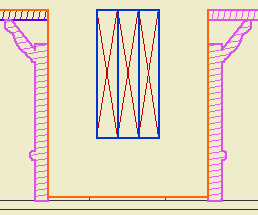
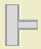
But I don't think we can do it. Certain objects, most prominently Wood Beam JAM9, have clever pen-related section behavior, which the uniform pen feature breaks. This is the wood beam at wall section scale; it knows to draw the X lighter:


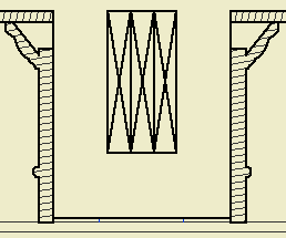
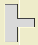
But the uniformity heavies up the X along with everything else:


Which is no good, and it really can't be fixed without patches or conversion to drawing, so what's the point. You can always make a line heavier by drawing over it; lighter, not so much.

The technique might be beneficial for interior elevations, since it turns the gray background off. And interior elevations don't show structure members. We should look into it.

A window. Location: 12 Furnishings/Casework

Basically, a niche. I guess you could use it for a wall niche too, with the usual caveats.

But the real idea is to build a bookshelf or cabinet etc from a thick (11"?) wall:


I marquee'd it so you can see the back.

More»

Location: 01 General / 3 Drawing Tools

To help locate overhead ceiling lines. This is a little weird but you'll get it.


More»

Location: 13 Special Construction

An alternative to Archicad's dismal, so-called vault. Last time I saw so many lines, it was election day in Ohio! Anyway.


More»

Sheet S3

Everything in the general framing plan discussion also applies to roof framing plans. There's a few special considerations:

• The roof framing plan should usually be generated from the top occupied story, not the roof story. For most projects, this is either the attic or the second floor. In the past, we have used the roof story, but not any more. It is very beneficial to show walls in the roof framing; in fact, we should show walls from multiple stories where applicable. By using an occupied story for the plan, it's one less story to be shown using the trick linked above.

• Show the outlines of the roofs. It is not feasible to show the roofs themselves, you must trace them or copy and paste from the 3D window in the classic style.

If you are showing the actual roofs in your architectural roof plan, put the traced/pasted roof lines on the +S Struct Note layer. If you are using the cut and paste method for the architectural roof plan, you can use the same lines for roof framing.

If you have dedicated structure roof lines (not reused in architectural), change the hips and valleys to a dashed linetype.

To put it another way.

Option 1 (preferred): Use roof elements on A Roof2 for the architectural roof plan. Use copied lines for the roof framing, on +S Struct Note. Switch the hip and valley lines to dashed.

Option 2: Use copied lines for the architectural roof plan, on +A Roof Plan Line. The same lines show in the roof framing. You can't do the dashed line thing.

• If hip and valley framing members are modeled, they require special attention to place them right. It's often OK to show these members as 2D only. There are two ways to do this: 1) The wood beam object has an option to turn the 3D off. 2) Put the beams on the S Framing layer, which is hidden in section.

For the last couple weeks, spying on people, I've noticed separator lines showing up in framing composites. I don't know how this happened, but it must be my fault, but you still have to fix it.

This is what I'm talking about:


Bad


Good

Even worse, it seems the separators got set to pen #1, which is just extremely bad.

More»

This is the main, simple text label for associated labeling of objects. It has one parameter, "Parameter to List". Put in the variable name of any text parameter in any object. The default is "desList". I'm using this name as a standard in many objects across the library. So you can put in any parameter name, but for many typical cases you can leave it alone.

Some objects will need more complex, customized labels, which we'll develop as we go along.

(To find the variable name of a parameter: Select the object you want to label and press Cmd+Option+O. (File -> GDL Objects -> Open Object) Find the parameter in the parameter list in the master window. The variable name is the first text column. It's an unfriendly-looking (probably) word-like thing.)

Objects that can be labeled using the "desList" parameter:

Wood Beam JAM9
Column Wood JAM9
Column Steel JAM9
Steel W Shape JAM9
Bent W Shape JAM9
Tuscan Column JAM9
RiserMeter JAM9

UPDATE: I added a list to the 'Parameter to List' parameter. In addition to desList, there's 'typeList', the 'Type for List' parameter of the crown tool, where you can put in a description of the crown, such as 'Type 1'. There's also 'crnDes', which is the name of the crown shape in the crown tool. With these parameters, you can label crown elements in the RCP.

You can still use any parameter name, not just the listed ones.

I also added a read-only description of each of the listed parameters.

Original date: 2004-12-15

Location: 06 Wood & Plastic / Trim & Moulding

A sloped crown object for shed roofs. It's similar to the Crown Tool.

Sorry about the 'a'. I found an issue I couldn't fix in place, so I had to make a copy.

More»