On Land

Environment Information
At Rill Architects we run ArchiCAD on macOS. If you work at Rill, this is your stuff. If you don't, but you work in ArchiCAD, you may find something interesting. Anybody else, I don't know.
RSS
Tips Archive

All Entries | 1 | 2 | 3 | 4 | 5 | 6

Download

This started, as so many things do, with making a symbol fill for a tile pattern. A challenge of symbol fills is they need to tile (left and right meet, top and bottom meet, invisibly).

You can make new grid, running bond, and herringbone fill patterns by duplicating the extant ones and changing the dims. Anything more complex, you need to draw and work out the tiling.

That's just the fill pattern, which is vectorial, meaning you can use it in plan and surface fills in elevation. But you are on your own in 3D (OpenGL, BIMx). If you are delivering BIMx, you need to keep your textures in sync with your fills. Here is a simple way to do that.

More»

We use labels to show the ID of doors and windows in elevations. The labels are identical to the marker tags used in plan, and the pointer is left off.

With the pointer off, it makes no difference whether you use the single-click or three-click geometry method.

geometry method
Doesn't help

The label will be placed at a (non-user-modifiable) distance from the user-clicked point. (The text appears the same place if you use the single-click method with the pointer on.) Since that clicked point must be on the door/window in order to place the associative label, the label itself will usually show up off to the side of the opening. Then you have to move it into place on the opening.

offset label
Wrong

(The way it should work: With the single click method and the pointer off, the label should be placed where the user clicked. This is one of those design issues that is so obvious I just call it a bug, opinions vary.)

Here is my best compromise method. Turn the pointer on. Use the three-click geometry method. Put the first click anywhere on the opening. Put the second click level with the point where you want the label. (After this click the Y coordinate is set.) Put the third click precisely where you want the label.

pointer label
Wrong, but be patient

Label all the openings in the elevation. Use find and select to select all the labels by name.

find and select
These ones

Turn the pointers off. The labels are off-center with the pointers on, but they will center on the third point with the pointers off.

good label
Done

Much faster than adjusting each one.

Here is a massing model showing existing conditions and a proposed addition. It is mostly done with renovation filters, with a couple of tweaks from graphic overrides.

existing-new massing model

Existing is overridden with one surface, the light color in the picture. If you are OK with existing elements not having fills in elevation, you can leave this override on. If you want the fills in elevation, you need to turn the surface override off, and switch it back and forth manually. This setting can't be saved with views or filters. We really need per-filter renovation overrides.

New is overridden with a different surface, the red in the picture. New elements are generally shown, not overridden. So the surface override can be left on. It is currently the only active override setting for New.

There is a new renovation filter, 07 Massing by Status. Existing=override, Demo=hide, New=override. Again, in all other filters, New is shown.

These are the graphic override rules:

Site Green finds 3D elements (in practice, they are meshes with the occasional slab) on the layer C Site3, and changes their uncut surfaces to 'Grass - Green'. Graphic overrides happen after renovation overrides, so while the site has existing status, it is not shown with the white color.

3D Lines Match finds All Types of elements, and changes their Line Pen to a medium gray pen. (It's our pen 137 in the picture, the default pen 2 would be fine too.)

Glass can't be overridden within windows and doors. (This would require attribute-level graphic overrides.) If you want clear openings of any sort, you have two options I can think of:

One way is to use 'Filter and Cut Elements in 3D' to hide the doors and windows. This will give completely empty openings.

The other is to use a graphic override rule similar to the site/grass rule, where doors and windows are chosen to be overridden by a clear surface. But, all parts of the doors and windows will be clear, not just the glass.

Some are redundant. I will probably think of more.

• Use the 'Working Dims Plan' Layer combination.
• Option+click on existing strings to maintain witness line justification as you move in.
• To add one string's ticks to another, select the string to keep and Cmd+click on the string with the points to add.
• Use the arbitrary angle setting when dimensioning walls, for auto-orientation.
• Use the 'place, rotate, drop' construction method with the CL object.
• To graphically justify a group of witness lines: Select the ticks. With the dimension tool, click on the segment and drag it to the desired justification point. Useful for backing up a few witness lines where the plan is very near.
• When you select a tick, the element the tick is connected to will briefly show as selected. To maintain this effect long enough to actually observe it, hold the mouse button down on the tick.
• Ticks can accumulate at a single point. If you try to delete a tick and it stays put, keep trying.

See also:
Dimensioning, General Principles

Are you interested in unsolicited email management advice?

This isn't a lightly covered topic by any means, but I find a lot of organizational guidance to be perfectionist bordering on, no offense, compulsive. I don't care if my inbox is completely empty, or if I have too many folders or too few. I only care that:

• No important messages get missed

• No less-important messages get to interrupt me. I'm busy.

Throughout this discussion, I am using a narrow definition of 'important', which is roughly: Having some legitimate claim on my near-term attention. And don't get me wrong, where would we be without so-called less-important stuff?

More»

Update: This method works through Archicad 12, with the key Recent Files. In 13 through 15, it still works, but the key you need to modify is called "Recent Documents". In 16, the Recent Documents key disappeared. Unfortunately I haven't been able to find where the recent documents are stored in 16 and 17.

Also: Under Mavericks (OS X 10.9), the developer of Pref Setter comes up as unidentified, and the current version will not run without modifying security preferences. The old version (I have 1.2.2) will run and seems to work fine.

It may happen that you would like to manually hack Archicad's recent files list. Recent projects are shown in the Start Archicad dialog box when AC launches. Recent projects and library parts are shown at File -> Recent Documents. One good reason to prune this list is that you can get apparent-duplicate items if you open a files from different locations, such as a server v. a local folder. Another reason is if you change servers and you need to make sure the recent items have the right address.

These are OS X instructions. We use the free utility Pref Setter to edit plist files. On Windows, use whatever Windows users use.

The AC preference files are at [home]/Library/Preferences/. There are a number of AC prefs; the one we want is com.graphisoft.AC .plist. You can right-click on the file and choose Open With... Pref Setter, or open the file from Pref Setter's File Menu.

The Pref Setter window will present all the 'Keys' in the plist file. Scroll to Recent Files.

Recent Files

Projects are listed first: Plan File_1., Plan File_2.,... You can delete any of these items. You can also modify the path in the Value field, to point to a different server, for example. Following the projects themselves, there is a Plan FileType_ item for each project. If you are deleting project items, you can delete these items as well, or not. It doesn't matter. Following that is a Plan Number item. This value is set automatically; you can ignore it.

After all the project list information, there is a similar arrangement for recent library parts that have been created or opened for editing. In this context the word 'Symbol' means library part: Symbol File_1., Symbol File_2.,... You can delete or hack these exactly like the project items.

(There are also integer keys for the number of RecentPlans (projects) and RecentObjects (library parts) you would like to see in the list. These are set to 12 by default, perhaps you would like more or fewer.)

We had to do some of this recently when we moved our projects, libraries, modules, etc. to a new server with a different address. When AC launches, it will try to make sure the recent files are accessible. This may lead to a prompt to log in to the missing server. Or, if the password for the server is stored in the user's keychain, the old server volumes can mount without you noticing it. Next comes confusion about where you are actually working, which is never good. Tip: Delete the password to the old server in Keychain Access. That way, you will be notified when AC wants to go looking where it shouldn't and you need to hack your prefs.

(To be honest, even after carefully working through this, I have seen AC mysteriously seek out the old volumes. There's some glitchy behavior going on, but it seems to settle down over time. We do what we can.)

Dwight Atkinson follows up his expert treatment of LightWorks in Archicad with The Artlantis Attitude. Dwight provides plenty of technical detail and strong opinion, while never losing sight of the professional and artistic goals of rendering production. You should buy this book and then you should read it.

The Artlantis Attitude is being distributed as a personalized PDF file. If you are skeptical you can contact Dwight directly at info.beginnernomore@telus.net to ask for a sample, and he's easy to find on Archicad-Talk. You can buy the book from various outlets that would show up in Google, or you can Paypal US$85 to that address.

The 3D printing consultant was fine with our 3D DXF until he got to the grade mesh. He requested that we send him an STL file, which we did not know what was. It is a 3D Stereolithography file and it's common in 3D apps. Archicad doesn't support it for export. We tracked down an open-source app called MeshLab which saves STL. It does not, however, open DXF. It does open 3DS. So we saved as 3DS from Archicad, opened that in MeshLab, saved as STL, done. From illiteracy to FTP upload complete in about three minutes. MeshLab is free and runs on OS X, Linux, and Windows.

Pen 50 is the poché pen. It is gray (80% +/- I think) in model and layout pen sets. It should be the background color of any cut fill in new construction. (Existing condition elements are white.)

That said, one of the advantages of pen sets is having black+grayscale output while the much more colorful model pens help you stay organized. So we have an alternate poché pen, #70, which is sort of tealy in model but looks exactly like pen 50 in layouts.

Elevator walls
The original intent for this pen was to distinguish multi-story walls (then new in Archicad 10) from their single-story brethren. I don't use multi-story walls as a rule, but I like them for elevators. In any case, the color difference reminds the use that when you edit this element there will be consequences on remote stories.

Lately I've been using them for other distinctive conditions.

Elevator walls
Modeling walls. For example, walls on the layer A Wall3 are usually needed to get a dormer to close in model. The color reminds you they don't inject their misleading selves into the output plans.

Profile Patch

Complicated 'patching' profiles. The color makes clear where the profiles meet the conventional elements.

Every viewpoint has a name and an ID. The name is important and is often used for output. The ID is never used for output, but wherever possible we use the ID to help organize the project map and view map.

Info Box name/ID
For viewpoints with with a marker, the name and ID appear in the Info Box and settings dialog. This applies to section, elevations, details, and interior elevations.

Properties in Navigator
For all viewpoints, the name and ID appear at the bottom of the Navigator under the Properties heading. Viewpoints with fixed IDs, such as stories, will have the ID field in gray.

The behavior of IDs varies among the viewpoint types, so here's a cheat sheet.

Story IDs
Stories have unique, fixed IDs based on the order of stories. They are ugly. We ignore them.

Section IDs
Section and Elevation IDs are created by the user, and they need not be unique, but the name/ID combination must be. (If you try to create a section/elevation with an identical name and ID, AC will automatically append a number to the ID.) Sections and elevations should have an ID roughly corresponding to their sheet number. Building elevations and sections get A2-1, A2-2, etc., and wall sections get A3-1, A3-2, etc. For sections, add a letter to indicate the direction the section is facing. Don't put the direction in the name. For 'Junk' sections, used for modeling support and not for output, the ID should be xn where n is a number. Junk sections x1 through x4 are placed in the template. (Yes, junk sections should usually be sections, not elevations.) So you end up with a section list of output viewpoints at the top, followed by all the junk.

Interiors IDs
Interior Elevation IDs should start with A5. I like to use the ID to sort the interiors by story: Basement is A5-0, first floor is A5-1, etc. Like the sections and elevations, the actual output sheet may differ. The sorting is to help you know where to look in the view map.

Detail IDs
Detail IDs need not be unique. (In AC10 and earlier, they had to be.) Still, it's a good habit to make them distinctive. I find it helpful to use the detail ID to give the 'category' of detail. For example, a bunch of eave details will have IDs of Eave01, Eave02, etc. The assembly type details have Type01, Type02, etc. Structure detail IDs start with S_ followed by a number. For all details, the name should be presentable for the automatic drawing title.

Worksheet IDs
Worksheets are a new, mostly redundant viewpoint type in AC11. We could easily live without them, but since they exist, we park all the straggly non-detail drawing things there. There aren't enough worksheets in a typical project to worry about sorting the list, so I recommend leaving the ID blank and just using the name.

The primary Schedules have an ID to sort them to the top of the menus. Incidental schedules don't need IDs. This may change.

Cameras and paths have unique IDs that can't be changed.

Summary: Viewpoint IDs are not used for output, so use them to help sort the lists. Names are used for output: Use the name you want to see on the paper.

The IDs that do matter for output are those of the layout book items; subsets, layouts, and drawings.

Drawing IDs are usually generated by the layout, either by the grid or the order of drawings in the layout book tree.

Layout IDs are usually generated by the subset.

Subset IDs are set by the user, and the subset ID becomes part of the layout ID.

Views also have IDs, but they should typically inherit the viewpoints' IDs, so the lists will appear the same to us. All view IDs can be customized or set to 'None', but you can usually just leave them be. In the templates, I have deleted all the IDs for story (plan) views, because stuff like "-1. Basement" looks idiotic.

What? I know how to open a file! Jeez!

OK. Just in case:

Always open AC files via right click -> Open With or by dragging the file to requisite AC icon on the dock. I do the dock thing; I'm just not a context menu person usually.

Most important, don't double-click PLNs. Double-clicking will only give consistent, predictable results if you have exactly one copy of AC on your machine.

When you install a new version of AC, as you soon will in the form of 11, that version becomes the default application for opening PLNs. So you double-click your AC10 project, it opens in 11, you don't notice the difference because there isn't much, you save it, and next time you try to open it in 10 it doesn't work. (Yes, backsave. Real convenient.)

Always keep current versions of AC on the dock. Even if you use the right-click method, the dock gives you visual confirmation that the right application is being used.

Graphisoft gives poor support in this area, by making the icons identical and naming each version, precisely, "Archicad".

Double-clicking files is one of those 'automatic' things that's great if you can trust it, but when it's not predictable it makes trouble. It's not just AC either, recently my .docs started opening in Pages for some reason.

What about that 'Change All' under Open With in the Get Info window? That fixed my .doc issue, but it doesn't reliably assign the right 'Archicad' version.

So, right-click or dock. If you have a bad habit here, change it now before 11 starts getting on your nerves.

Update re app icons: Mr. Briggs to the rescue.

11 Icon

Homeworkers: When's the last time you took home the office Library Container File?

The library is always changing and the LCF is updated every Monday at the very least.

Window slabifying slabs

A slabified window is easy, considering it's a window and windows are hard. Build up a few slabs of varying thicknesses and IDs and you're done.

But it's tedious to set all the thicknesses and IDs, right?

How about a module of slabs preset to the proper settings? Then it's just a matter of option-clicking and magic-wanding each part.

You can arrange the slabs so they resemble a window section to help you remember what's what. And, yes, you can call out the parts with text, too, right.

I put one of these for a 2x6 wall at 3 Resources / Modules / Window Slabify.mod. Other wall types would vary but it's a start.

Rectangle Profile
Pretty tricky
This is so trivial/obvious that I hesitate to point it out.

You can't rotate a conventional beam element about the long axis. (Why? Dunno.) But you can rotate profile beams. So you just need a rectangular profile.

But if it's so obvious, why isn't there such a profile in the default templates, among the faux-proof-of-concept distorted steel shapes? And why wasn't there one in our templates until yesterday? Dunno that either.

LCF Folder
Archicad 10 offers a new all-in-one library file format, the Library Container File or LCF. In Archicad 9, you could use a PLA archive file as a library. LCFs are pure library stuff, with no model space or attributes.

It is allegedly faster to load the libraries as a single large file than from folders full of folders full of individual objects. But I must say in my informal testing I haven't observed a dramatic difference among loading library folders, PLAs, and LCFs.

In addition, there's at least one characteristic of LCFs (and archives) that is disadvantageous. You can't save objects into them. So no new objects and no editing. (You could view this as an advantage from a standards point of view; nobody can mess anything up.)

In other words I considered using an LCF for the Rill & Decker Standard LIB but decided against it. There's no change in everyday library management.

But! There's a huge advantage to the LCF in one specific case: Copying libraries to a flash drive to take them home. The R&D library is about 15MB. Copying its 1300 or so items to a USB 2.0 drive takes over two minutes. Copying the same library as a 15MB LCF takes, drum roll, three seconds.

It also takes the guesswork or other syncing strategies out of keeping your home copy of the library up to date. Just bring the LCF home and overwrite the old file.

So I'm providing the library as an LCF for this purpose. The file lives at 2 Libraries / Library Container Files. I will do my best to update it when anything important changes. This is pretty often, so make sure you check it regularly.

You still need to manage project libraries manually.

When they mashed up PlotMaker with Archicad, they had to make views-in-layouts into proper elements, rather than flaky PM things. So we have the Drawing element, which can be edited as a polygon, assigned favorites, and given a marker, all of which makes the mashed up AC views-in-layouts much more pleasant than their ancestors.

But drawings aren't just for views; You can use them for PDFs. They're not just for layouts; you can place them in any model window.

DWG Drag
And finally, you can use them to place DWGs. Rather than opening or XREFing the DWG, you can drag and drop it from the Finder directly into a model window, where it becomes a drawing. If you just need a DWG for tracing or reference, this is the way.

When you drop the drawing, the only question you have to answer concerns the units. Use 1 inch. If the drawing is 12 times too small (I think that's how it works), drop it again and choose 1 foot.

A few other points:

• A big advantage of the drawing method is there's no layer contamination.

• Drawings placed in this way can be updated, just like view drawings, and will appear in the drawing manager.

• The drawing will come in with the default settings of the drawing tool (though there will be no title). As for the pen set, use '*Layout', which is overwhelmingly black and works for most DWGs.

• If you're placing DWGs for use in output, more pen management is likely in order, which is another topic.

• Tip: Put the drawing on a remote story and set that story to ghost. Now you can work normally without accidentally selecting the DWG.

There are the layer combinations for work and the layer combinations for output. In the past, the output LCs have had all their layers locked. The only reason for this was make clear to the user that they're not in a working combination. Not a critical point but there it is.

Now there's a stronger reason to have the layers unlocked in output LCs. In AC10, you can right-click on a drawing and choose 'Open source View' to, right, open the source view. (In AC/PM9, this command existed but it never worked as far as I could tell.)

Open Source View
If you are viewing a drawing and see something that needs fixing, you can open the view and get right to it. So the layer locking should get out of the way.

In the architectural LCs, all the visible layers are unlocked. In the specialized plans (electrical, e.g.), only the special layers are unlocked.

A subtle but powerful feature tweak in AC10 is the addition of the 'Previous' option for ghost story display. Very simply, it shows the last story you were on as ghost.

Now you can go back and forth between the basement and first floor, e.g., while always keeping the other story in sight.

Here's a somewhat lateral tip. Use previous to show either the story above or below without using the Stories or Go To Story dialog at all. To show the story above as ghost, just go up and then immediately down (Cmd+6, 5). For the story below, down then up. Very quick, and habit-forming.

It is not possible to delete the entire Favorite list at one time. You can only delete them one at a time, which, if you have a lot, no thanks.

But you can write over the entire Favorites list with another list. If this list happened to have, say, one item on it, well that would be pretty easy to delete.

We have the Favorites file 'Blank.prf' for this purpose. It resides at 3 Resources / AC / Favorites. It consists of a Favorite for the Hotspot tool, Archicad layer, pen 10, that's it.

On the flyout on the Favorites palette, choose 'Load Favorites', and open the Blank.prf file. You will get a dialog offering to merge or replace the current list. You want to replace. (Merge adds the new list to the old.)

Delete that hotspot fave and you've got your blank slate.

Why delete the Favorites? It helps clean out attributes. Attribute Manager will report that an attribute is in use if it is part of a Favorite. With no Favorites, it's one less place to look before you're sure you can delete something.

And of course you can clear them temporarily. Save the Favorites you are using, clear them, do whatever you need to do, then load your saved list back.

As long as I can remember, we've used a polygon wall for a fireplace, with a 3D-only wall or slab above to take the chimney to the ceiling. This method has been developed pretty far.

This new method isn't going to give you the 1" chimney section for CDs, but for schematics, it feels a little simpler.

More»

This is obsolete as of Archicad 15 which brought new Renovation.

MacDonald is a long-completed new home project. I don't know how long, but the important thing is that it's an AC7 project. We are reviving it for the purpose of some interior renovation. Naturally, we want to use the data we have. There are a few issues in working on a project of this vintage:

• All of the elements on new (.N) layers need to be treated as existing.

• The libraries.

• There's a couple of minor pen issues, to the extent that pen issues can be minor.

• The project is full of CD-phase annotation. All we want is the geometry.

More»


I built this newel out of ordinary stuff. Crown and baseboard objects, walls, a mesh for the top. In plan, there's a square fill. All the elements go on the layers they would if placed directly in the project. The model parts are on A Stair3, and the fill is on A Stair Rail.

The newel is all alone in a separate project file. I hotlinked it into the main house project, and copied it around. There are eight of them.

It is easier to maintain than if I had saved the whole thing as an object, which was my first idea.

I am also using the newel PLN to generate the section and elevation details of the newel. Can't do that with an object. Remember you can have drawing links to different projects.

When I needed a half-version of the newel: I created yet another separate, blank project, and hotlinked the newel into that too. Then I placed a big slab and SEO-subtracted away half the newel. Then I realized that the plan fill was still whole, which is no good. I broke the hotlink, which leaves ordinary elements. (So I could have simply merged it after all.) I adjusted the fill to cover only half the newel. Then I hotlinked the half-newel project into the main house as above. (If I change the whole newel, I'll have to do the half over. Not ideal, but the alternatives aren't either.)

Something to think about...

I've added an 'Alternates' folder to zTemplate folder, in 1 Design. It should have been there before, sorry.

It gives me an opportunity to discuss alternate handling, or at least to give you one case study. Vassos, although it's under construction, has occasional lapses into design development. The clients were interested in seeing alternatives for one part of an elevation. We offered two, which forked into three.

I saved a copy of the project for each alternate, with a descriptive name, in that Alternates folder. I developed the model for each alternate. We wanted to present a perspective and an elevation for each choice. Since the alternates are in separate files, and all the alternates are separate from the main PLN, it's easy to simply use the views you already have. You can't mess anything up.

To present the choices, I created a new subset in the main layout book. There's no reason to create separate 'books for each. Within the new folder, there are two layouts for each alternate. I hooked the new layouts to the 11x17 Master. Then I imported the perspective and elevation views from each PLN.

Once the decision had been made about which version to use, it was time to begin treating that scheme as the real project. I renamed the main PLN, which had been untouched, with a date, and moved it to the '6 Old Files' folder. I saved-as the anointed alternate with the original name of the main PLN, at the top of the project folder. This means the layout book never knows anything happened. If you change the name of the project, you will need to re-link your views.

In the end, we have three alternate PLNs set aside, the pre-alternate version of the project intact, and the layout book not disrupted. And a compact record of the alternates' presentation. Pretty good.

In this case I was fortunate that, since the project was 'done', there was no other work going on anywhere. Presenting alternates in the DD phase is trickier, especially if the design decision is slow in coming. If you need to keep the main project moving while the alternates are being developed, it is better to merge the chosen alternate elements back into the main project.

I've added a new layer combination to the templates, 'Stretch House'. It's intended to help when marquee-stretching the whole project. It simply shows and unlocks everything building related, while hiding the section markers and everything site-related. I hope you find it useful, or can at least ignore it.

If you search Google for a simple question with a concrete, factual answer, it will give that answer ahead of all the usual links.

For example, I just put in 'how many square feet in an acre' and got '1 acre = 43 560 square feet'. Thanks, that's what I needed, bye. Other recent applications include comparing the land areas of Maryland and El Salvador. El Salvador is twice as big. And the Earth weighs 5.98x1024 kilos.

Sheet A2-1
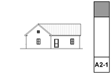
S/E Status (Model/Drawing). It is just really strongly recommended that all building elevations and sections be model views. Developing model sections is a little harder than elevations, but anyone can do it with practice.

I usually keep S/E's set to Auto-rebuild.
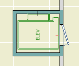
S/E Element Placement. Marker ends should not extend too far beyond the building itself. Our section elements go on a non-printing layer, and we use a separate object to show the section locations in plan. This is because it is difficult to reconcile the extent of the cut with the desired graphic presentation of the markers. That is, To get the markers looking nice you need have them much more extensive than is required to create the view itself.

Cut sections using the section marker Plain Section JAM9. This simple marker just shows the ID and a flag to indicate direction.

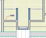
Elevations should be as close to the building as possible; the marker should be stepped where necessary to achieve this. Watch out for eaves and gutters.

Sections often require a lot of tweaking to get them to cut through interesting/clear/consistent stuff on all stories. Watch for undesirable effects of stepping with respect to roofs. Where a section cut is perpendicular to a roof's slope, try to avoid stepping the section within that roof. If you can't avoid it, discontinuities in the roof can be patched, but the patch becomes a maintenance issue if you edit the S/E element again.

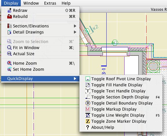
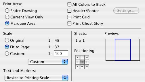
Section depth should be minimized in order to improve performance. The depth should reach only the most distant element you want to see; usually it's a ridge or a chimney. Infinite depth sections should never be used. Zero-depth sections come in handy sometimes for generating details, but building and wall sections should always have some depth. Section depths are typically off in display options; toggle them using Karl's marvelous add-on.

Layers. All annotations go on the layer +A Arch Note Reg Scale. This includes text, arcs and splines used for leaders, and notation objects. All added 2D work should go on +A Misc Line, but this is not a critical issue. Since S/E windows usually only generate a single view, layer discipline is not as important as in the plan. You should, however, make consistent use of the Arch Note layer, to maintain the option of turning the notes off to display the S/E image by itself.
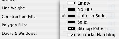
Vectorial hatching.

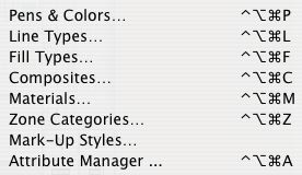
Elevation (and 3D) hatching is generated by the 'Vectorial Hatching' setting of the material in Options -> Attribute Settings -> Materials. The pen of the hatching should typically be 150, which is light gray.

Display of the hatching is a setting in the model tab of the S/E element itself. Hatching slows down generation considerably; in typical use it should be off. Before publishing, turn the hatching on for all the markers by selecting all of them and checking the box in the info box. The hatching switch setting is not saved with views, which is too bad.

Unwanted lines.

Ugly bits which are complex can be patched. To hide simple cases of a few unwanted lines, use a fill which matches the vectorial hatching of the elements involved (shingles, stone, etc.), and has an opaque background. For blank walls you can use a solid fill of a white-printing pen. I use 80, which is purple, so I can see the areas I've masked. Masking fills and patches should go on the layer +A Misc Line. The use of masking elements becomes a maintenance issue.

Rendering of depth.

Foreground elements should be outlined with a heavy (5-weight) polyline. There is no reliable way to do this automatically, it's tedious. One tip: for symmetrical building parts, outline one half and then mirror. Another: Outlines can often be copied and pasted to the opposite-facing elevation and mirrored across the origin.

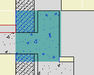
Use Marked Distant Area where appropriate. When using it, check 'Use One Pen' and use pen 30. Pen 30 is gray in AC and 1-weight black in PM. You need section depths on in display options to edit the MDA depth. Don't forget the shortcut.

When you combine outlining with MDA, you get three levels of rendering: Fills on and outlined, fills on with no outline, and fills off.

Model pens. Except for walls and objects, elements are drawn in 3D with their floor plan pens. Walls have a dedicated 3D pen, which should be a 3-weight. (Typical walls are 13.) Objects can have a separate 3D pen, either as a parameter or hard-coded, this will vary. It is a long-standing wish that all elements have a separate 3D pen.

The ground. The ground mesh section settings should be: Fill='Air Space'; Background pen=91; Cut pen=6-weight. (I like green land, so 36.) These settings give an invisible fill with a heavy ground line. The bottom and side lines of the mesh should be obscured by the object Grade Mask JAM8, which goes on the +A Misc Line layer.

Annotations.

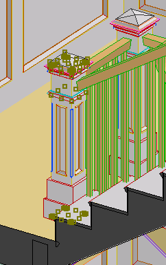
Elevation notes. The main materials and building elements should be noted. This includes wall finishes, trim parts, decorative columns, panels, railings, chimneys, etc. To align the notes, use the object Note Column JAM9, in the drawing tools folder. Notes on the right side should be left-justified with the leaders starting at the first line. Notes on the left side should be right-justified with the leaders starting at the end of the last line.

It is permissible to fully annotate one elevation on each sheet, and then only point out unusual features on other drawings on the same sheet.

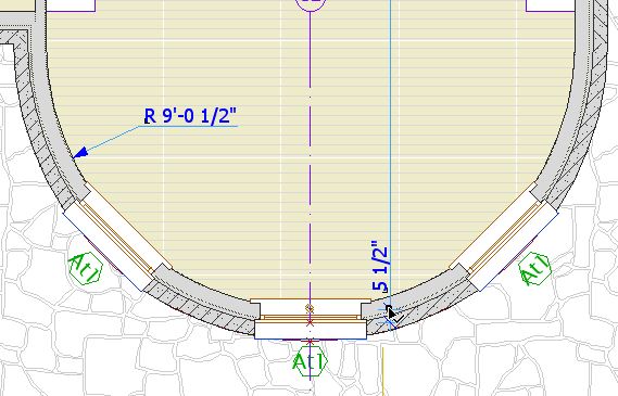
Levels. Use the object 'Elev Marker JAM8'. Elevation views should show the Z-height of each story. It is helpful to draw a dotted (not dashed) line through he elevation at each floor level. Dotted lines need to be heavy in order to be visible; use a 4- or 5-weight. In sections, levels should be should be shown for ceilings as well as floors, and for interior floor level changes (such as garage slabs). Level objects will auto-display their Y position, which is the height. They should be dimensioned to show the relationships among them.

Knee wall heights should be dimensioned in section.

In sections, unusual ceiling or floor conditions may be labeled with Slab Elev JM9. Examples: Lowered ceilings in small rooms, a stepped slab in a theater.

Roof pitches should be noted in section and elevation with the label Roof Slope JAM9.

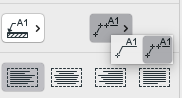
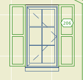
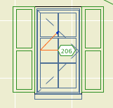
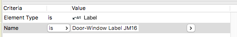
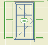
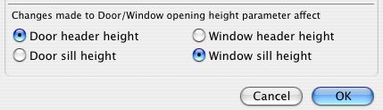
Doors and windows should be labeled with Door-Window Label JAM9.

Structural members in section should be labeled with Description JAM9. Joists are shown 2D-only using 'Joists Sect 2D JAM9'. Our standards don't support modeling the joists.

If you drag a dimension string, the texts will re-center themselves on their segments, assuming the texts have not been moved manually.

You don't actually have to drag the string anywhere, just a drag and a double-click will do it.

The only way a dim text would be off center without you moving it is if you customized the text.

Who cares? You, because you probably changed some texts to read EQ or something, and re-centering them by hand is a cumulative chore.

So, after changing the texts to read whatever, (deselect the texts,) select the string, Cmd+D, clickclick. Note: if the dimension tool is active (very likely), you have to do a Drag command; cursor-drag will edit the witness line length. You can drag with the arrow tool and it works; I think the Cmd+D method is better since you don't have to be precise. Any texts that you moved manually will stay put. AC remembers which those are.

I just dimensioned all the Vassos ceiling lights on the electrical plan, which, if you've never had the pleasure, boils down to a LOT of EQ EQ EQ EQ EQ. So I was really happy with this discovery.

Sort of cross-posted here.

(Originally posted here. Added examples.)

Here is the Geometry Methods info box tile.


Geometry Methods are the ways of making a shape with a tool. The 'GMs' are only available in the info box, not in the settings. You can switch geometry methods in any tool by typing G.

The first button is one click placement. The object will be created with the default X, Y, and rotation. Example: A recessed light fixture, since it's not stretchy and it doesn't matter how it's rotated.

Second is rotated placement. Two clicks. First is anchor point, second is angle. X & Y will be the defaults. Examples: Anything that you would turn to face a certain direction. A lot of things. Sinks. Light switches. Sconces. Centerline symbols.

Third is rectangle placement. Two clicks. First is anchor point. Second is the diagonally opposite point. The same method is available for polygons (slabs, fills, etc.) Not all objects will be placable this way; only stretchy* ones. By this method you can graphically set X & Y, but you can't give values. Example: Crown Tool in coffer mode.

*Interlude: Stretchiness. Objects are stretchy if they have hotspots in their 2D scripts at the 0, A, & B extents, OR "Hotspots on bounding box" is on in their "Details". Don't worry about this now. An example of a stretchy object is Bed 01 in the Furniture folder. The only way to know if an object is stretchy is to try it, or look in the script. Most rectangular objects should be stretchy.

For "stretchy" placement to work, you have to have a corner set as the insertion node in the settings. If a non-stretchy node (e.g., the center) is the insertion node, you get one-click simple placement. In the plan preview window in the object settings, the insertion node has a box around it. You can choose a different insertion node there by clicking on it.

Tip: When you Option-click (pick up settings) on an object, the node you clicked becomes the insertion node.

The fourth button is rotated rectangle. Three clicks. First is the anchor point. Second is angle AND length of first side (X). Third is length of second side (Y). Example: Crown tool coffer in a rotated space. The same method is available for polygons. If a non-stretchy node (e.g., the center) is the insertion node, you get two-click rotated placement.

The key is not to get hung up on "rotated". I use this method all the time for non-rotated polygons, because you can use R to set the length of both sides on the fly. Example: counter slabs. When placing an object such as a bathtub this way, you need to know which way the object goes; X is first, Y is second. If you do it backwards you get the drain on the long side.

If an object is "linear", only stretchable in one direction, stretchy placement still works. If using rotated placement (4th), the second click only sets the angle, and the third click sets the length. Using the fourth button with a linear object enables you to draw it very much like you would a line. Examples: Lots. Drawing title, crown tool in straight mode, steel and wood beams, cut lines. Sometimes it's hard to predict which side of the "line" an object will be drawn; if it's wrong just mirror it.

Choosing the right geometry method saves a lot of after-rotating and -stretching, and is therefore much faster.

You can magic-wand a zone stamp to place a polygon using the geometry of the zone itself. It works even if the zone polygon is hidden, and saves you the trouble of finding an edge, since zone edges tend to coincide with lots of other stuff. Magic-wanding the middle of a room is often impractical due to interference of other lines.

Handy for finish-floor slabs, lower-the-ceiling-in-one-room slabs, floor material fills, etc. Just make sure your zones are updated first.

Cross-posted here.

I was going to patch up this post, but I decided to do a new one. The old one is mostly right, I just wanted to add...

• In AC9, there is a menu command for Create Independent Detail. That means you can have a shortcut for it. In our keyboard setup, it's Ctrl+D. (What. Oh. Tools menu. Please don't do it that way. I hate menus.) Also nice, when you create an independent detail, it opens automatically.

• For some reason, most of my projects open new independent details at absurdly zoomed-out views. Like the window is a million feet across. I can't fix this, it's not stored in the prefs. It's always a good idea to work near the origin. You can zoom to the origin quickly by placing an object there and then doing a fit it window.

• Wall sections should be Sections. It's so clear to me now.

• IDs. They still need to be unique, but the ID will now take up to 31 characters, so you can be very non-cryptic. You can have spaces, though I don't use them. I like it to be clear that the first word is the ID. To review, use the ID to say what type of detail is in there, with a number so maintain uniqueness. Use the name for a fuller description. Eave1 Typical, Eave2 Shed, Eave3 Porch.

I have been drawing all the engineering details myself, based on their sketches. I keep these separate by beginning all their IDs with "S_".

• Detail markers: For areas, use Detail Area JAM9. For flags, use Detail Flag JAM81. These markers show the ID in Archicad and the drawing/sheet number in PM layouts. For assemblies, use Assembly Marker JAM81. This marker maintains the ID, which is the same as the (non-autotext) drawing number in each assembly detail. It also gives the sheet number, which is automatic. I have developed the habit of putting my schedules and assemblies on sheet A3-1, so they stay put as sheets are added.

• Remember you can open a detail from any marker, not just the original one.

• The biggest hassle with the detail tool is the fact that you can't put a detail marker in a detail window. Maybe someday. If you need to call out a detail within a detail, use an object. Remember the autotext referencing hack.

Once I put up that screenshot of the detail marker, I noticed that the gibberish components of the two autotexts are the same. The difference lies in the DRAWINGNUMBER_R and LAYOUTNUMBER_R tags at the front.

This means I can have reference markers (section and detail flags) that just need to be told the gibberish segment once, and can build the autotexts themselves. For these objects, instead of copying the entire autotext in PlotMaker, just copy the data within the second pair of angle brackets: "<9BEA5D4E-8700-11D8-8AA9-000A95A7B33A>".

I have added this ability to Detail Area JAM9. In the settings, paste the gibberish into the "Paste Autotext Here" field. In the drawing and layout number fields above, you will see the completed autotext fill in. You can still put non-auto text in these fields; if you delete the "Pasted" data, the fields will empty and unlock, and you can use them however you want.

I redrew the "Flagstone Random" fill pattern, in an attempt to get it to redraw faster in vectorial. I cut the number of lines by about 50%. There are now only 1700 lines in a 10' x 6' rectangle.

It's a little faster. Not as much as I expected, but every little bit yada yada.

If you want to try it, you can pull it from the Vassos project using Attribute Manager. Here's the before and after:


I think the new one looks better too.

If no one complains I will replace the fill in the templates in a little while.

I was happily (!?!) putting in the rake mouldings for the gambrels on Vassos. On the sixth one, the outer rake failed to subtract from the steep roof of the gambrel. All the others had worked. Imagine my joy when I saw that all five previous subtractions at the same condition had also failed.

The "solution" is to slightly change the edge angle of the upper roof edge. In my case, the angle of the edge when mitered to the upper roof was 74.3651º. I rounded up to the nearest hundredth of a degree, to 74.3700º. To keep the section through the miter looking presentable, I had to change the adjacent edge angle of the upper roof.

Over time I have have seen these subtractions continue to deteriorate, and I have to change the angles again. It's a pain, but there is no other way to model complex rakes.

Update: This issue is greatly improved in 10 and in the later patches of 9.

Remember that it's very easy to drag drawings between layouts while in Tree by Subsets view.

If you have a big pile of new drawings (details, interior elevations) destined for multiple sheets, import them all at once into one layout. Then distribute them by dragging them in the tree.

Q
When I paste elements, is there a way to select those elements?

A
Complete the paste. Undo (Cmd+Z). Redo (Cmd+Shift+Z).

Q
Working in section, is there a way to reveal selected elements in plan?

A
Yes.

Q
How can I tell what elements were affected by a marquee stretch?

A
Undo, redo. The affected elements are selected. Current story only, natch.

When an editing action is undone, the edited element will typically be selected. Comes in handy.

It's slow to open the settings dialog when you can use the info box.

It's slow to choose File -> Save rather than typing Cmd+S.

It's slow to choose File -> Merge rather than typing Opt+M.

It's slow to hunt down the close button at the top of a window rather than typing Cmd+W. However: it's slow to bring a window to the foreground so you can close it, if you can click its close button in the background.

It's starfish-slow to choose Edit -> Copy, choose Options -> Stories -> Go Up A Story, choose Edit -> Paste, rather than holding down Cmd and typing C, 6, V.

It's canyon-formation-slow to choose Tools -> Display Order -> Bring Forward, Tools -> Display Order -> Bring Forward, Tools -> Display Order -> Bring Forward, Tools -> Display Order -> Bring Forward, rather than holding down Ctrl and typing 6, 6, 6, 6.

It's slow to right-click and choose Undo, right-click and choose Undo, right-click and choose Undo, right-click and choose Undo, right-click and choose Undo, rather than holding down Cmd and typing Z, Z, Z, Z, Z.

It's slow to drag windows around until you see the one you want rather than use Exposé.

It's slow to go to Display Options when you can use this.

It's slow to go to the Project Map, scroll to the Details part, right-click on it, and choose New Independent Detail, rather than typing Ctrl+D.

It's slow to right-click and choose Open Section/Elevation, or Last Section/Elevation, but unfortunately we don't have a choice.

The fastest way to cancel anything is to type Esc.

The fastest way to deselect is to type Esc.

The fastest way to remove marquee is to type Esc.

The fastest way to switch to the Arrow is to type Esc. The second fastest way is to type Right Arrow, and that's better a lot of the times because it doesn't require that you have no selection and no marquee.

The fastest way to activate the Marquee tool is to type ` (the key above Tab).

The fastest way to activate the Wall tool is to type 1.

The fastest way to activate the Slab tool is to type 2.

The fastest way to activate the Roof tool is to type 3.

The fastest way to activate the Text tool is to type E.

The fastest way to activate the Fill tool is to type F.

The fastest way to activate the Door or Window tool is to type D or W respectively.

The fastest way to change the reference line side of a wall is to type C.

The fastest way to change the geometry method (box, rotated box, polygon, etc) of any tool is to type G. It's also the fastest way to switch the orientation of the dimension tool.

The fastest way to turn on gravity and choose the gravity element type is to type V.

You can do all those things without moving your left arm. You have to move your left arm a little, but it's still fastest to

...activate the arc tool by typing 0 (zero),

...activate the Object tool by typing (letter) O,

...activate the line tool by typing L,

...activate the Dimension tool by typing /.

...toggle the rotated grid by typing K.

Plenty more where those came from.

I will try to flesh this out when I have time. It's a solid method, and touches on a lot of useful techniques.

• 3 coincident walls for fire box: Stone veneer, block core, fire brick. All go on A Fireplace.

• Use roof for back of fire box; SEO add to firebrick wall. Roof goes on X SEO General.

• SEO Subtract firebrick assembly from core. Subtract FB assembly and core from veneer.

• On top of firebox, 2 slabs or walls, one inside the other, veneer and core. Both go on A Chimney3. Subtract core from veneer.

• Smoke chamber: Mesh. connect firebox void to smoke chamber with slab. Both go on X Flue. Use print-white pens. Subtract both from the core Chimney3 element.

• Flue: Object, Flue JM9. Can be plumb or offset. Build the flue out of segments, attach to smoke chamber, work your way up. Some flues will show in plan, check the "Show Cut" box in settings.

• Subtract the flues from everything they pass through.

• Use slabs for hearths, adjust Chimney3 elements as needed. Fill in with Chimney3 walls or slabs as needed.

You can copy and paste elements between facing sections/elevations, and easily put the pasted elements in the right place. Examples: Room names in sections, and elevation outlines.

The trick is to mirror the elements across the global origin.

More»

Hotspots do two things:

1. Placing a detectable point where there isn't one.

2. Making a point detectable in PlotMaker, for the purpose of aligning drawings to one another or to the layout.

In practice, I use very few hotspots. I try only to use them where they will be permanent. A common example is a hotspot at the maximum of a curved wall, so the wall can be dimensioned.


Such permanent hotspots should be locked.

I almost never use them as a workaround, and if I do, I delete them immediately. If you get in the habit of placing a lot of hotspots and leaving them around, the workspace becomes cluttered with extra detectable points, making it harder to be sure you are detecting the point you want, leading to errors.

Further, hotspotting an arbitrary point to detect it is usually not needed. Special snap points and the ghost story make it possible to detect any point worth detecting, and you can move the origin to "transmit" a point through stories. You can also use CenterPoint JAM9 as a hotspot, and it has the added benefit of showing on multiple stories. And really, how often do you need to detect a point that's truly in the middle of nowhere?

If you've gone on a hotspot binge for whatever reason, you can delete them all at once: Activate the tool, Select All (Cmd+A), delete. Since your permanent hotspots are locked, the won't be harmed in the purge.

Hotspots are also created by certain variants of command clicking. This has occasional usefulness, but it more often happens by accident. Be aware of it so you don't wonder how you made a hotspot without the hotspot tool.

The hotspot on the wall is in line with the red line:


To place a spot like this, select the line, activate any tool except the line or arrow tools, and Cmd+click on the wall.

If the arrow tool was active, nothing would happen. (I think this is a bug.) If the line tool was active, the line would extend to the wall. (Cmd+click acts like adjust where the active tool matches the selected element.)

In most cases, I would just extend the line.

A truly, I think, useless feature crops up when you Cmd+click on a roof edge instead of a corner, when trying to find the height of a roof at a point. You get a hotspot at both corners bounding the clicked edge. And you don't get the height box, which should tell you you're doing something wrong.

While hotspots are usually low-utility in modeling, they are almost required in laying out sheets. Hotspots are visible and detectable in drawings placed in layouts. They cannot be printed. When placing alignment hotspots, use a prints-black pen (I like 5), so you see them against the white of the layout area and the grey of the rest of the window. Some applications:

Update for AC10: I'm leaving these in for now, but these techniques are generally obsolete in AC10. In 10, everything in a drawing is detectable, just like you're looking at the model directly. Many drawing alignment issues can be handled directly now. (Plan alignment in 10 here.)

• Hotspots at the corners of the drawing area in the plan window, for aligning the plans on the sheets. Since all the plans will use them, they should be on the Archicad layer. The templates have drawing area objects and hotspots for each sheet size. You'll probably need to move them to frame your project correctly. Though the object shows on all stories, the spots need to moved on each story. Alternately, you can move one group and copy it to the other stories, deleting the old ones. These spots should be grouped and locked. In PM, you may have to resize the drawing frame to fit these spots.

• The drawing area matches the available layout area within the title block. There should be hotspots in the title block at the four corners of the big empty space. There should also be spots at the center of the sheet number box, and the left edge of the (optional) sheet title box. In the templates this is done.

• Use hotspots to align drawings as they are aligned in the building, such as two wall sections next to each other, or parts of the same wall section. Place hotspots on a common point of both drawings, such as a wall or floor plane, then drag the drawings in PM to align the spots.

You can drag and drop libraries to the Library Manager from the Finder.


Like this

In Library Manager, the History tab shows the libraries that have been loaded recently (since the last Clear or Clear All). This list is independent of any particular project.

Typically we use the exact same libraries all the time. But there are exceptions; sometimes you need the version 7 library, for example. If you've loaded that library recently, you can add it from the history tab instead of scrolling through the whole Local/LAN tree.

It's also helpful if you take projects home. When you open a project in a different location, the library manager will come up because the servers aren't there and your local Archicad folder path is different. But the history tab remembers the local instances of the libraries, making it easy to load them quickly.


If you load a "wrong" library at some point, you can use the "Clear" button to delete it from the history so you're not tempted by it in the future.

A particularly self-starting member of the Archicad community, Karl Ottenstein, has developed an add-on called QuickDisplay, which allows us to assign keyboard shortcuts to various display options. The commands are toggles, which means you can strike a key turn the Section Depth (e.g.) on, and then strike the same key to turn them off. He has generously allowed this add-on to be used free of charge. Here is the Archicad Talk topic where mad, righteous praise is heaped upon him.

Here is Karl's page with full instructions for the add-on. I will summarize the high points.

Get the file from 3 Resources : Add-Ons. Place it in your local Applications : Graphisoft : Archicad 9 : Add-Ons. Launch or relaunch Archicad.

Your Display menu should now have a QuickDisplay submenu at the end. Here you will see commands for toggling various display options.


QuickDisplay Submenu

Naturally, and I hope obviously, you don't go to this menu to activate the commands. That wouldn't be much of a shortcut would it. The commands have to be on a menu in order to have shortcuts assigned to them.

As you can see, I only have shortcuts assigned to two of the commands, Section Depth and Line Weights, on F4 and F5 respectively. I toggle the others much less and I don't need a shortcut for them. You can do whatever you want.

I have updated the RND Keyboard scheme with these two shortcuts. You can import the updated scheme at Options -> Work Environment. The scheme is located at 3 Resources : Work Environment : RND Profile : Shortcuts.

For information on assigning shortcuts, see the Archicad Reference Guide, page 153, or ask for help.

The question is, when you change the height of a door or window, does the head or the sill move. In real life, we want the head of the door to change, but the sill of the window. In olden days the sill would control no matter what. In AC8, they offered a preference, but it applied to both openings, so either the door or the window still behaved wrong, which if you think about it is no improvement at all.

Now, in AC9, they have it straightened out:


Options -> Preferences -> Construction Elements

Here's a new trim layer. It shows in the same layer combinations as the other 'F Trim'. In addition, it shows in the reflected ceiling plan, which is the point.

Place Crown Tool objects on this layer and you can avoid redrawing the crown for the RCP.

The layer has been added to the templates. Add it to current projects if you like. More on creating layers here.

Why?
1. Maybe you want to email it somewhere (like home).
2. Smaller files are more reliable. Less chance of corruption.
3. They save and open faster.

How?

More»

OK I should have done the foundation stuff in the meeting today because it would have given me the opportunity to demonstrate polygon editing for walls, lines, etc.

More»

You can't place a detail marker in a detail window. Rats.

You can change the linked drawing of a placed marker by opening the settings and clicking 'Browse' underneath the detail name.

I've updated the other post with this info.

On the Archicad Help Menu, beneath the first two items, you will find two lists of items.

The first list consists of links to PDFs, including the Archicad manuals. The PDFs reside in the Documentation folder within the Archicad folder. Any PDF placed in this folder will appear in the menu.

The second consists of links to web sites. The links reside in the WWWLinks folder within the Archicad folder. Any link placed in this folder will appear in the menu.

What it does:

• Limits the area for a Find & Select.

• Limits the area for a Select All, or a tool-specific Select All.

• Limits the model displayed in the 3D window.

• Marquee-stretches. Elements wholly within are dragged, elements partly within are stretched. Groups off!

• Limits the elements to save as a module. With heavy marquee, makes it possible to save a multi-story module.

• Limits the print area, instead of resizing the window.

• Makes it possible to show section perspectives.

Remember that with a marquee placed, everything in side the marquee is selected for any purpose other than changing settings. All the transformations and copy transformations will work. Delete will work. Eek!

See Also:
Archicad 10 Reference Guide pg. 56

You have clicked some points for your dimension string. You have not checked the geometry method for the correct orientation, horizontal or vertical. Well over half the time, due to Murphy's Law, the wrong one is selected. You click to place the string, and get nothing. You have to start over. You are sad.

If you are dimensioning walls, you should be clicking on the line of the wall, rather than the corner, in order to dimension the core. (This isn't the tip; it is current standard practice. I hope someone is praying for you if you aren't dimensioning this way.) Choose the third, arbitrary angle, geometry method. With this setting, the string is forced to orient perpendicular to the wall, regardless of the wall's direction.

For two strings with the same orientation, select one, then Cmd+click on the other. The second string will disappear, and its points will be added to the selected string.

Forgot something else...

In 8.1, we have the option of placing a marquee to limit the print area, instead of fiddling with the window itself.


Print Marquee Area, among other things.

Click 'Copies and Pages' and select 'Archicad' to view these options.

As far as I know, this option has always existed, but I've only fully internalized it recently.

Try this display option in your working plans and sections views:


Uniform Solid and friends

It causes walls in plan, and all elements in section, to display as solid fill of the pen of the fill pattern. In plan, this means that only the corner of the wall itself can be detected, not the inside drywall corner. This eliminates the problem of accidentally aligning counters, floor fills, and such to the core of a stud wall.

I have taken the liberty of changing the working views in the templates to employ this option.

This is about four years old but I wanted to explicitly point it out...

All the attribute-related options on the Options menu (Pens and Colors, Line Types, etc.) use the Ctrl+Opt+Cmd modifier combination with the initial letter of the attribute.


I'm sensing a pattern.


Oh, those three.

Update: A couple of these (notably materials and composites) broke in AC9 due to conflicts with default shortcuts in OS X. Pens and fills still work. Keep the Attributes toolbar on.

Update: For AC10 I put the quick layers commands in the main toolbar, so you don't need the palette.

Window | Floating Palettes | Show Quick Layers (Ctrl+L).


Quick Layers Palette

The Quick Layers palette enables you to:

Unhelpfully:

• Toggle the display of all the layers. All the showing layers become hidden, all the hidden layers show. Shrug.

• Ditto for lock/unlock. Shrug.

Very helpfully, under 'Selection's Layer':

• Hide, lock, or unlock the layer of selected elements, even for multiple layers at a time. Similar to the 'Layer' sub-context menu.


Remember?

Unhelpfully again:

� Hide or lock all layers. Big shrug.

The palette will close when you quit Archicad, unlike the standard palettes. Just reactivate it when you start with Ctrl+L.

I've added a module for Site Plan info to the Modules folder (in 3 Resources). It contains all the elements for contours, boundaries, notes, etc. I did not include separate note stuff for the 120 & 240 Note layers, but you'll probably live. N.B.: 8.1 only!

Don't forget: In AC8, the escape key now performs the cancel function. This makes it consistent with all other software in the solar system. 99% of the time, hitting ESC will be faster than mousing over to the Cancel button, or right-click-canceling.

It's also another beautiful, inspiring, timeless, indestructible tower on the magisterial edifice that is The Keyboard, as compared to the moldy-straw-1st-little-pig-shack of Mousing Around Clicking Buttons, Menus, Sub-menus, and Sub-sub-menus.

In other words, learn the shortcuts, and use them. And we'll plan our escape.

LOON ISLAND, ME -- Due to the wet spring and summer, the lake is a good 18-24" higher this year. Remember that the dock is simply resting on the lakebed and is not tied down in any way. If not kept above the water, it can blow away in high wind/waves. The idea is to elevate the whole thing while moving it closer to the shore. Keep in mind:

The dock is heavy. You will need three or four people.

You will get wet.

Wear shoes that can get wet, and that will stay on your feet; there's some mucky spots on the lake bottom.

There are rocks. This is good, because you will need to put them under the feet of the dock to elevate it. It's also bad, because you will have to lift the dock far over some of them.

The dock is built in sections that can be taken apart and moved separately. The only wrench is an adjustable one, there aren't any sockets in the cabin. The nuts are under the dock, which is awkward. Remember 'Righty Loosey Lefty Tighty' because the nuts are upside down. Try not to drop the nuts in the lake.

What? Oh! No, no, no, not that dock. That's in the System Preferences under 'Dock.'

Perhaps you are looking at an element in an S/E window, and want to find the element in the plan.

Select the element in the section. Drag it somewhere. Undo. Return to the plan. The element will be selected. Or, delete it, and Undo.

Caveat: The plan window must be on a story where the element is showing. Use Zoom to Selection to find it. If Zoom to Selection shows only the S/E element, you're on the wrong story.

Here's a summary of the single key commands in Archicad. I didn't know some of them either. G & C will save you a lot of mouse milage.

  • A - Activates the Angle Coordintate
  • B - Activates the Base Value (in the Info Box)
  • C - Cycles through the Construction Methods
  • D - Activates the Divisions Snap Option**
  • G - Cycles through the Geometry Methods
  • H - Activates the Angle Bisector Modifiers**
  • O - Activates and switches between Offset and Multiple Offset**
  • P - Activates and switches between Parallel and Perpendicular Modifiers**
  • Q - Cycles through the Quick Alignment Methods (when Shift-constraining)
  • R - Activates the Radial Coordinate
  • S - Cycles through the Grid Snap Options (former esc function)
  • T - Activates the Top Value (in the Info Box)
  • X - Activates the X Coordinate
  • Y - Activates the Y Coordinate
  • Z - Activates the Z Coordinate
  • 2 - Pans Left
  • 4 - Pans Down
  • 6 - Pans Right
  • 8 - Pans Up

** Broken in OS X. Too bad, epecially P.

You're in an S/E window and you want to change something in the settings of that S/E. Go back to the plan, right? Nope, double-click the S/E tool in the toolbox!

Update: In AC10, right-click in the section window and choose Section/elevation settings.

All Entries | 1 | 2 | 3 | 4 | 5 | 6