Several different kinds of change, which may overlap. New versions mean new workflows, and that means layer changes.

Template Archive
All Entries | 1 | 2 | 3 | Older »
My view of the template is this: Anything you always, or even usually, do on a project should be started in the template. Stories, sections, elevations. Views, lots and lots of views. Not just some layouts, almost all the layouts. You're going to publish PDF and DWG. You're going to print. You're going to do sketch render and BIMx. And if you don't, so what. It's easier to delete or ignore the extraneous items than to create new ones. You don't want to create a layout book, with proper auto-numbering subsets, in every project. The favorites mean the tools are ready to go.
Let's call this the inner template. It is just the PLN file.
There's other stuff: The outer template. What these items have in common is that they are present in every project (so they should be in the template file), but they are also company standards that may change slightly over time (so they should be centrally maintained). Paradoxical!
These items use four different techniques driven by how they are used and maintained:
• Text document PDF placed as a drawing element in a layout.
• 2D modules hotlinked in detail viewpoints.
• One-story PLN hotlinked in the floor plan.
• External views placed as drawings in a layout.
General Notes
We call them that because they are notes, that are general. Are they specific? No, obviously. We maintain PDFs of general notes for all the jurisdictions we typically work in. The PDF pages are placed as drawings in a layout. The template default jurisdiction is Montgomery County, MD. If you are working in DC, use Link Drawing To to switch to that PDF. All the PDFs are in one folder on the server.
When we learn of a new or changed requirement of a certain jurisdiction, or a better standard practice we want to implement, we modify the notes document (in Word), and re-save the PDF. Projects using that document can then update the placed drawings and the notes are always current.
Again, these are *general* notes, with no project-specific information. All the running projects should have current general notes. Specifications and project-specific notes go elsewhere.
The standard abbreviations are handled by a similar linked PDF strategy.
Standard Details
These are technical details with no architectural ("aesthetic") content. Mostly they talk about wall types, roof assemblies, flashing, etc. If the project has slate roof, regardless of the eave design, the documents should have a standard detail showing how a slate roof is done.
Such details are placed as hotlinked modules in detail viewpoints. The template contains some of the more common ones, and others can be hotlinked or merged as needed.
The shared details themselves are in a PLN file, with one detail on each story. Doing it this way lets you publish the modules all at once with a publisher set.
So, you start a project, and though you are in schematic design, there are already standard assembly details in the project. Like with the standard notes, if we decide to make an improvement to a standard detail, we can re-publish that detail and all the projects using it can update the hotlinks and be up to date.
On the other hand, if you want to modify a wall type for the specific project, you can break the hotlink, and modify the detail as needed. When a new detail is developed in a project, it should be brought into the details PLN and published as a module so it's usable in the future.
By providing hotlinked details in the template, we have some standard details done, as well as a head start on modifications we might need for the project.
Electrical Symbols
Update: I think a proper Electrical Symbols Schedule is better.
The electrical symbol legend is a hotlinked PLN file (not a module; it's just one story) placed in the template's floor plan on story number -2, a non-publishing story below the Basement (-1). There is a view saved of the legend, which is placed as a drawing on the electrical sheet layouts.
The legend can't be placed in a detail or worksheet viewpoint, because some of the symbols are lamp elements, which can't be placed in details. (The rest are objects.)
The legend itself is handy for doing electrical plans: Set the trace reference to that Footings story, and you can eyedropper (Opt+click) on the symbols.
Again, the legend is standard in the template when the project begins. If the 'master' legend is updated, the hotlink manager will alert the user. OTOH, if the user wants to break the link and modify the legend, they can do that.
Drawing Symbols and Standard Fills
On the cover sheets we have legends for drawing symbols, section fills, and surface fills. These are external views from a PLN file, placed as drawings on the two (Sizes D and E) cover sheet master layouts. (We use size C internally and for preliminary work, but never for official submissions or CDs. So no cover sheet with the legends.)
Because the sheets are different sizes the legends are as well, and there are separate views for each sheet size. The Drawing Symbols.PLN file has four stories.
The symbols and the section fills are published at 1:1 scale, so those two legends can be next to each other on one story. The surface fills are "Model Size", so they have to be published at an architectural scale (1:48) in order to show anything in the tiny boxes of the legend. They have their own story.
Two stories for E size, two for D. The four stories are saved as views with the appropriate 1:1 or 1:48 scale.
These legends rarely change, but when they do, the placed drawings can be updated.
Renovation is a feature set to control the display of existing, new, and demolished elements in the workflow of addition and renovation projects. It began in Archicad 15. This feature means we no longer have three of each layer in addition projects.
In the Renovation workflow, there are three kinds of elements: Existing Elements, Elements to be Demolished, and New Elements. This property is the Renovation Status. With a few unimportant exceptions, all elements have a renovation status, and it cannot be blank.
Renovation Filters control whether and how elements of the three statuses are displayed. Filters are saved with Views.
The filters control whether the elements of each status are Shown, Hidden, or Overridden.
I hope showing and hiding are self-explanatory. If elements are overridden, their appearance is controlled by Renovation Override Styles. The attributes covered by the styles are: Line type; Line pen; Fill type, pen, and background pen; and material. There is no consideration for fill category, so cover and cut fills are handled the same. (Fail.) There is only one set of override styles, and they do not vary by filter. (Another fail.) For example, you can't have one filter where overridden demo elements are dashed, and another where they are dense dashed. Whatever the style of overridden demo elements, that's the style for all filters where Demo is overridden.
Because the override styles are responsible for the appearance of overridden elements, elements of different status will have the same "natural" settings. You don't change the line type or fill color of individual elements to show they are demolished.
The styles are set in the template and should be considered set-and-forget.
There are also Additional Filter Options for existing and demolition elements. Right now the only one of these we are using is to turn off markers for doors and windows.
And, keep an eye on it, it will try to mess with you. The current filter can change by viewpoint; it can be new construction in plan and existing conditions in 3D. When this happens, stuff will "disappear". Check the palette. Once the filter is set for a given viewpoint, it seems to stay put. (Both the default filter and the default status seem to sometimes change spontaneously, especially when opening a project on a different machine.)
The status setting is not transferred by eyedropper/syringe. The default setting on the palette always controls. You can change the status of an element in the settings dialog under Tags and Categories, but the palette is obviously easier and a better habit.
Our Override Styles
New elements are never overridden, and have no override style changes. (N.B. This is our decision, not a design limitation of the new status itself.) New elements act as if the filters don't exist. The background pen is gray (#50), same as it ever was.
Existing: The fill is overridden to be Empty Fill. The fill background pen is overridden to be pen 91 (white).
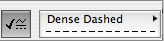
Demolished: The fill and fill background are overridden like existing, and the line type is overridden to be Dense Dashed.
Again, the natural settings of existing and demolished elements are the same as new. The override style turns them white and/or dashed.
See the appendix at the end of this post for examples of the different kinds of output.
Our Renovation Filters
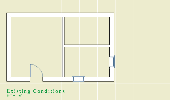
01 Existing Conditions
Existing: Override
Demolished: Show
New: Hide
This is used for building the existing model, and publishing the existing plans and elevations.
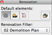
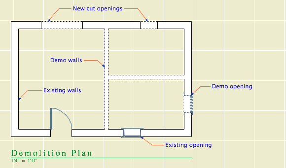
02 Demolition Plans
Existing: Override
Demolished: Override
New: Hide
All the walls have white background, and the demo elements are dashed.
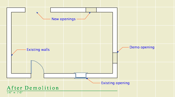
03 After Demolition
Existing: Override
Demolished: Hide
New: Hide
Existing elements only, with the demo elements removed.
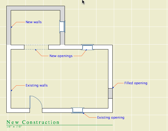
04 New Construction
Existing: Override
Demolished: Hide
New: Show
This is used for most work and output. Existing walls are white, new walls are gray.
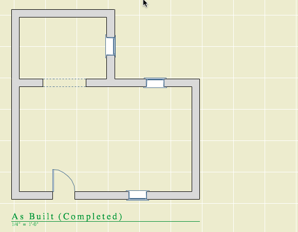
05 As Built
Existing: Show
Demolished: Hide
New: Show
This shows the project when finished, as if it were all new. All the walls are gray.
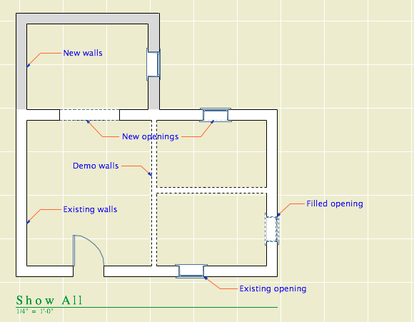
06 Show All
Existing: Override
Demolished: Override
New: Show
All statuses are shown, and you can tell the statuses apart.
How to Demolish Things
Select an element and, on the renovation palette, click the demolished button. That changes its status from Existing to Demolished. Unless the current filter is Demolition Plans or Show All, the element will vanish. If you switch to Demolition Plans, the element will reappear with dashed lines.
Demolishing a wall
That's basically it. Of course, you might have to split an element first to demolish only part of it.
The big difference between the new method of demolition and the old layer-based one is in the handling of doors and windows. Doors and windows are now demolished the same way as other elements. Just select them and change their status. There is no need to split the wall and demolish the piece with the opening in it. When you demolish an opening, it is replaced by a portion of new wall. (Note: That new piece is shown using the natural settings of the existing wall. It's no longer being overridden. That's why all elements have the same natural settings.)
Further, you don't need to split an existing wall to place a new opening. Just place it normally (check the status!), and you will have a new-status opening in an existing-status wall. And in the demolition plan, the new opening location will be shown dashed.
Renovation Filters in New Projects
Unlike layers, renovation filters have only one purpose. (There's not going to be any hacking the demolition status to do something else.) If there's no renovating or demolishing, you don't need them. So in the New Home template they are not used. The filters are in there, but they are modified to show all statuses all the time, with no overrides. All the views are set to Show All. The palette can be put away.
Special Cases Where Multiple Layers Are Still Needed
Even on a New Home project there are some sneaky existing conditions, those pertaining to the site. We have separate layers for existing and new topography contours. We have layers for existing, "demo" and new trees. We have an optional layer for backing up the existing site's mesh.
I don't think these things are what renovation filters are for, and I can't see "using" them throughout a New Home project just to address these tiny parts of the project work. So we ignore the filters, and we have a few oddball E and D layers left. To remove a tree, change its layer and enjoy the nostalgic moment.
Don't Demolish Notes, Silly Rabbit
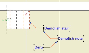
Another layer we didn't delete is +D Demo Note. I have heard of people trying to use one note layer and then make some notes demolition notes by changing their status. This is a category error. Renovation status is for project elements, which represent real things in the world. You're demolishing that note, are you? How? What is the result of demolishing it? Keeping different types of annotation straight is a proper use of layers.
And if we still have the Demo Note layer, we still have the Demo Plan layer combination.
Changes to the Templates
Removed lots of layers.
Implemented renovation filters and override styles.
Applied filters to views.
Updated favorites and default layers.
Created pen set for existing plans.
Secondary Info on Renovation
All element types have a renovation status except hotspots, drawings, figures, and viewpoint-creating tools (Section, etc.).
Elements have a setting in the Tags and Categories division where they can be set to show only on a specific filter, rather than "All Relevant Filters". There's also a button on the renovation palette for this setting. I can't imagine an occasion to use this. That setting is where the warning comes from when you delete a filter: "By deleting a renovation filter, you will lose all elements which are shown only on that specific filter." Since we don't use that setting, we aren't scared of this warning. Further, I don't see the need to delete filters very often.
The filter settings can be imported and exported; they are xml files like Model View Option combinations. (But they import badly, extant filters can't be overwritten.)
There seem to be no GDL globals for renovation status, which seems like a missed opportunity.
In Model View Options
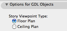
Among the least heralded new features of Archicad 11, tucked into the bottom of the Model View Options dialog, is the modestly named 'Story Viewpoint Type'. Not heralded at all, in fact; there's no mention of it in the New Features Guide. I understand why they don't want to call it out too loudly. Its impact is rather narrow, and the Archicad library itself makes very limited use of the feature.
Right, what is it. It's the long-awaited (by me) environment switch to put the floor plan window in 'Ceiling Plan' mode. Wouldn't it be nice if things could draw themselves dashed in plan and solid in RCP or vice-versa. Less tracing, less maintenance, more unity. This is a pet issue of mine, so I'm happy to see it, even in its narrow, modest, unheralded current state. I'm calling it the 'ceiling switch' because no one knows what 'Story Viewpoint Type' means.
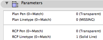
The switch gives the opportunity to have objects draw themselves one way in plan and another way in RCP. But: Only objects, which includes doors, windows, and lamps. It does not apply to regular modeling elements such as slabs and beams. Keep hope alive.
I've made several objects which take advantage this tech, and I plan to retrofit more as we go.
Ceiling Line JM11
The first one is, a line! Haha! I know, if things are more unified you should draw... less! It's ironic. But there's more to come and this serves to illustrate the basic idea.
You could do the reverse: Let the RCP use the object settings and customize the plan parameters. Either way.
What's it for? Roof overhangs. You have to draw them anyway, because showing the roofs themselves is a mess. Use this object instead of a line, and get the overhangs in plan and RCP simultaneously. And: Miscellaneous ceiling lines such as those in an attic.
Template Changes
We need a new layer, which is A Ceiling All. This layer shows in plan, RCP, and all the model combinations.
To handle the ceiling switch itself, we need a new Model View Option combination, which is A4 RCP. In previous versions, the RCP used A4/S0/M/P; now that one's just S0/M/P. When migrating a project, you'll need to create this model view combination and assign it to the RCP views.
Automatic titles are not new to 10, but title objects are new, and now that they are objects, we can use them, which is new.
A drawing title is essentially a marker for a drawing element. Like section markers, detail markers, symbol labels, and door/window markers, you choose the title from a popup menu rather than from an object-type browser.
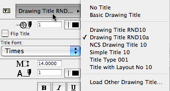
As with all markers, there's no way to restrict the list. It shows all the loaded drawing titles, and it's up to you to pick the right one.
Elevations, sections, site plans, and details should all use automatic titles. Plans are the only drawing which has an object (Plan Title RND10) in the window. PDFs placed for notes ordinarily shouldn't have a title. Scanned details might, it depends.
Since the title and its settings are part of the drawing element's settings, you can change them in groups using the Drawing Manager. (Note: You must have a layout as the frontmost window to do this; otherwise the title tab is grayed out.)
Drawing Title RND10a is very similar to Drawing Title RND9a. There's a couple of 10-specific changes:
• By default, the title uses the name of the drawing (which should come from the name of the view, which should come from the name of the window). You can put in a custom text under the 'Title' tab in the drawing settings dialog.
• Titles don't have a length parameter like a regular object. So the Length parameter controls the length. You would normally adjust this graphically:
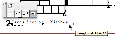
The length still has a minimum equal to the title text length.
Again I have to apologize for issuing a '10a' revision. There was one issue with Drawing Title RND10 that I couldn't fix in place. That title would appear right on the corner by default. The new one appears 3/8" below the corner, which makes it easier to move the title as needed. Note the 'move marker' palette button:
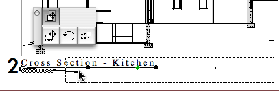
And, full disclosure, I broke the minimum length thing, but now that's fixed.
UPDATE 2007-12-11:
• You can set the Orientation of the title. You can have the title rotate to align with the Drawing (default), the Layout, or a Custom Angle. Use the Layout option to keep the title horizontal when you rotate a drawing. This is optional, and it's not always right. For example, if you rotate a wall section to fit on the sheet, the title should rotate too. I can't think of a purpose for Custom Angle, but it wasn't hard to put in there. If you do ever use it, the angle is graphically editable.
• You can choose a manual scale from a list. Leave the field empty to use the drawing's true scale. This is usually correct. To show no scale text, choose 'blank' from the list. You need to set a manual scale for a scanned detail PDF; now you can choose it from a list.
The templates have a fax transmittal as part of the layout book.
There are the layer combinations for work and the layer combinations for output. In the past, the output LCs have had all their layers locked. The only reason for this was make clear to the user that they're not in a working combination. Not a critical point but there it is.
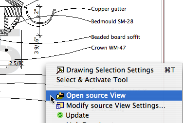
Now there's a stronger reason to have the layers unlocked in output LCs. In AC10, you can right-click on a drawing and choose 'Open source View' to, right, open the source view. (In AC/PM9, this command existed but it never worked as far as I could tell.)
In the architectural LCs, all the visible layers are unlocked. In the specialized plans (electrical, e.g.), only the special layers are unlocked.
In the templates for 10, I've modified the layer combinations as suggested here. There's a couple of tweaks since then.
Changing the LCs is a minor change compared to changing the layers themselves, which can be very perilous. (There are a couple of layer changes in the new templates. Just a little peril!)
In this theory of layer combinations, there are three main types, and then a couple oddballs. The three:
• Output. Used by publication views.
• Working. Where you spend most of your time.
• Special Tasks. Unusual LCs for doing a certain task once in a while. E.g., Site cutting, building stretching, elevations with just notes.
The new LC arrangement makes these categories clearer. The working LCs begin with numbers. The output LCs begin with the letter of their sheets. The specials begin with x. The oddballs: The binder LCs begin with z. Since they're not used until the very end, they have to be last. 'zzz All' is sort of administrative, and you never use it in real life.
I've tried to make the purpose of each LC self-evident in the name.
Here's the list. (Existing/addition-only LCs are indicated by '*'.)
- ! Ex1 Existing Plan*
- ! Ex2 Existing Elev*
- ! Working Existing Model*
- ! Working Existing Plan*
- 0 Working Model
- 1 Working Floor+Roof Plan
- 2 Working Elev+Sect+Detail
- 3 Working Wall Section
- 4 Working RCP
- 5 Working Interiors
- 6 Working Site 120
- 6 Working Site 240
- A1 Floor+Roof Plan
- A2/3 Elev+Sect+Detail
- A3 Wall Section
- A4 RCP
- A5 Interior Elevs
- A5 Enlarged Plan
- C1 Site Plan 120
- C1 Site Plan 240
- D1 Demo Plan*
- E1 Elec Plan
- F1 Furniture Plan
- M1 Mechanical Plan
- P1 Plumbing Plan
- S0 Foundation Plan
- S1 Structure Plan
- S2 Structure Model
- S3 Structure Wall Mask
- View 3D
- View LW Render
- x Background Plan
- x Elevation Notes
- x Gross Area
- x Object Lab
- x Shoot RCP
- x Shoot Roof Plan
- x Site Cutting
- x Stretch House
- x View Chimney
- x View Flues
- x Working Dims Plan
- x Working Trim
- x Zones
- z Binder Elevation
- z Binder Plan
- z Existing Binder Elevation*
- z Existing Binder Plan*
- zzz All
The current standard for library loading is to load only the folder specific to the project. That is, don't load the entire 2 Project LIB 9 folder. I updated the templates so that the only libraries loaded by default are 1 Rill & Decker LIB 9 and AC9 Library Special Edition.
When the time comes that you need project specific objects, create a folder in 2 Project LIB 9 with a name like Projectname LIB.
When the project is completed and moved to Past Projects, the project library should be moved to 2 Libraries / Other LIBs / Past Project LIBs.
If you know of an object in a project library that you could use, ask the person who made it to move it into the standard library. Or, remember that you can load objects individually.
The idea is to not load objects that you will never use, such as other people's patches.
To facilitate the creation of post-project binders.
Starting with AC 10, we will use 'real' section markers.
When we started with AC 5.1, there were fixed section marker styles. (Like the fixed dimension ticks and arrowheads to this day.) We didn't like the available styles, so we adopted the policy of showing sections in plan with an object, independent of the SE cutting element. The independent object also means we can fudge the placement of the marker, rather than being bound to its actual extent. And we can have that two-headed marker option.
In 8 (I think), they instituted GDL section markers, so we can in principle make markers any way we want. In practice, scripting SE markers is rather quirky, and I decided to punt, waiting to see if it would improve.
The main disadvantage of the independent object is that you need a workaround to refer to the drawing in the set.
In 10, they have overhauled tweaked the reference method internally. It's mostly good, but the workaround linked above is actually made worse. I can't take it anymore.
And no, the scripting is still weird. In 10, SEs have visible hotspots that aren't detectable. Gimme a break. But on balance the time is now to switch to real sections.
Summary.
Object Pros: Total scripting control. Flexibility in graphic placement. Cons: Awkward drawing referencing. People think we're weird.
Real SE Pros: Unity. More intuitive, not fighting the program. Automatic referencing. Cons: Less graphic flexibility.
Standards and template updates are below the fold.
This layer is for operator elements which you would like to show in plan.
Example: You can use the filleted disc and box objects to cut a ceiling, and display those cutting elements in the plan with a dashed line. You still have to draw them over in the RCP, but two elements is better than three.
Another example: A slab subtracted from a wall to make a niche.
All Entries | 1 | 2 | 3 | Older »