This clever trick from Patrick May at 4dProof about labeling zones in section has two parts. The clever part is the lateral thinking of labeling things in the zones rather than the zone itself. The other part is the introduction of autotexts in labels in Archicad 21.
The lateral thinking part could have been discovered versions ago, you just needed to script the label in GDL because there was no label autotext.
So when I got done slapping my forehead I wrote a label in Archicad 20 which matches our zone stamp and the object we have been using to 'label' rooms in section. And while the label autotext is very handy, but, as always, GDL gives you more power and control.
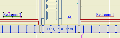
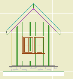
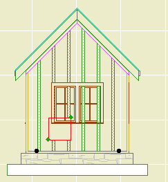
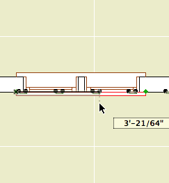
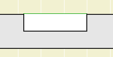
First, let's review the clever trick. You can't label, or even detect, zones in section or elevation. What you can do is label a model element, and have the label state what zone an element is in. (Related zone condition is determined in plan. The elevation of elements and the height of zones doesn't matter.) Turn the pointer off, and you have a word which is the name of the room floating in the room. The label is live data - if you rename the zone, the section labels will be updated. And, you don't need to know the name of the room to label it.
These element types can report their related zone:
• Object
• Lamp
• Morph
• Beam
• Column
• Stair
• Wall, if zone boundary, with caveats
These element types are ineligible:
• Slab
• Roof
• Shell
• Wall, within zone
• Door
• Window
• Skylight
• Railing (AC21)
To label the room, you need to find an eligible element in it. In our projects, considering that not every room needs to be labeled, almost every room has a lamp, object (moulding, appliance, plumbing fixture, etc), or beam in it. If there are none of these in a room, I suspect the project isn't far enough along to be labeling rooms in section.
The main walls of the room, since they are usually boundary walls, are a good choice with caveats. There may be two (or more) zones related to the wall, so you need to be sure the right one is shown. In Archicad 20, sometimes there are two zones available and the label just ignores one of them. (This seems to be fixed in Archicad 21.) If the walls won't cooperate, you'll need to find something else to label.
The basics described so far also apply to labeling with autotext in Archicad 21. These are the additional features of this scripted label:
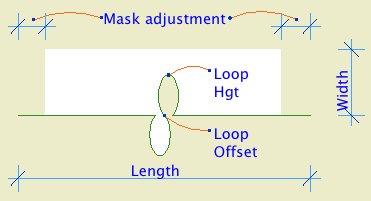
It precisely matches our standard for room names, including the fussy underline and the ability to 'stack' two-word names.
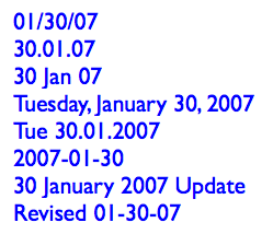
It can show the name and the number or both, and the font and size of these texts can be different.
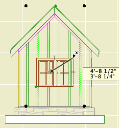
It tries to help if you label something ineligible. If you label an ineligible element, there is no text to display. In this case the autotext label just sits there, blank and invisible. Go ahead, place a bunch of empty labels until you notice the pattern! The scripted label helpfully states 'something is wrong' in this case. (The two things that can be wrong are that the element is of an ineligible type, or it is not inside a zone. GDL doesn't offer the ability to tell these conditions apart, otherwise I would have the label tell you.)
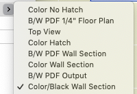
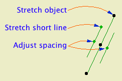
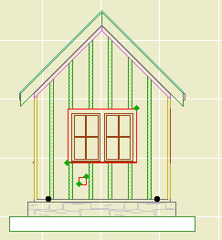
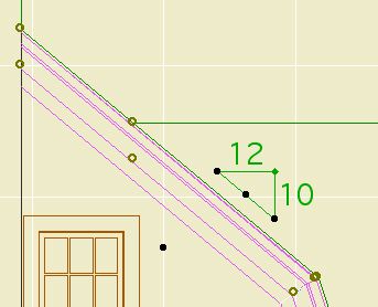
If you are labeling zone boundary walls, you can switch between the two zones the label knows about. (Autotext only offers one zone and no way to switch that I can see.) There is a checkbox in settings for using the 'other' zone, and even better there is a graphical switch at the top of the text block. (It only appears for walls with zone zones.) Switching doesn't always help: Since walls can bound more than two zones, the one you want might not be offered. You'll need to label something else.
Update, July 7, 2017
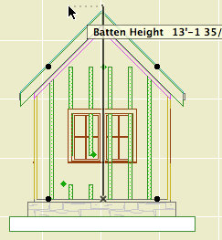
Only the main properties (name, number, etc) of the zone are available to labels. Our zone stamp has additional parameters, such as an optional short name which can be shown in small rooms. These parameters aren't available to the label, so you can't use the short name for rooms that are small in section. In that case you can make the text size smaller or use the number instead.
I have tweaked the label so it behaves more civilized in the settings dialog.
Download