On Land

Environment Information
At Rill Architects we run ArchiCAD on macOS. If you work at Rill, this is your stuff. If you don't, but you work in ArchiCAD, you may find something interesting. Anybody else, I don't know.
RSS
Objects Archive

« Newer | All Entries | 1 | 2 | 3 | 4 | 5 | 6 | 7 | 8 | 9 | 10 | 11 | 12 | 13 | 14 | 15 | 16 | Older »

Brick Rowlock
Location: 04 Masonry

An extrusion in the shape of a sloped brick rowlock course. Set the Angle and Brick Width of the rowlock, and the Thickness and Air Space of the veneer it rests upon.

Rowlock Section
The Mortar Bed option will draw a wedge of mortar below the brick in large scale sections. The brick itself uses the object's fill setting. At building section scale, the whole thing is modeled using the object's fill.

Yes, you could use a custom profile for such a thing. But if you wanted to change the slope or the brick dimensions you would need to draw a new profile. And profiles can't change in response to the scale.

Profiles are simpler, at least until you have too many of them. Objects are smarter. Now if we could script a profile...

Bracket Strut JM9: More top and bottom end shapes: Cove, chamfer, and fillet.

Chamfer Cutter JM9: Chamfer multiple corners at once.

Rafters Decorative JM9a: Like the eave ladder, you might want to see exposed rafters in the reflected ceiling plan. But you need to be able to hide the portion of the rafter object that is hidden by the main roof. Adjust the Top Hide Distance to meet the main roof cut:

Hide rafter top

Location: 06 Wood & Plastic

A sloped series of boards to support a flying rafter.

This thing is hard to show in place; here's a section through the eave of a dormer, showing the dormer wall in elevation:

Eave ladder section

The Roof Slope can be selected from a familiar list of n/12 slopes, or you can use a custom angle.

You can choose the board Stock from the list, or use a custom Height and Width. Spacing is measured along the slope.

eave ladder plan
The boards are shown in plan as a bottom view, taking the roof slope into account. By default, all the boards are shown.

eave ladder RCP
Why a bottom view? This is a trim object, and will often go on a 3D-only layer such as F Trim Ext Hi. You would never see it in a regular plan. But you might want to see it in a reflected ceiling plan.

eave ladder hide edit
But in the case of this dormer, you would want to hide the boards that are obscured by the main roof. Stretch the Top Hide Distance to do this.

Location: 06 Wood & Plastic / Brackets

An Arts & Crafts type bracket. Parameters: Length, height, width, top/bottom thickness, top/bottom end treatment, strut thickness, width, and top/bottom inset.

The end treatments are Square, Ogee, and Pyramid. May 2008 update: Cove, Fillet, Chamfer.

You can turn on "Both Ends Same" to use the same values for the top and bottom. In this case, the bottom-related parameters are hidden.

Most of the parameters are editable in 3D.

Though I kept the '9' in the name, this is for Archicad 11.


Originally posted 2005-03-29

Location: 06 Wood & Plastic / Trim & Moulding

A series of battens for board and batten siding. There are parameters for Width, Thickness, and Spacing. For a single batten, set the spacing to zero.

In order that you can do a whole wall with one Battens object, you can have up to eight Holes in the batten arrangement. Turn on as many holes as you need and fit them to the windows and doors. You can do this in section or elevation using the editing hotspots.

Battens 1
This is an excellent throw-down-and-fix situation. I placed the object along the wall in plan. Now I can fine tune it in elevation. Note the gap in those two battens; that's one hole.

Battens 2
You can stretch the height using the editing node at the center of the top. The ordinary nodes at the ends won't work, don't ask me why.

Use solid ops to trim the battens to the roofs.

Battens 3
Each hole has two editing nodes. The lower one moves the hole, and the upper one stretches its height and width. The red box shown here is optional; turn on the Show Holes parameter if it makes it easier. You can still edit the hole if the box is not shown.

Battens 4
Position the hole first, then stretch it. In most cases, you'll do this by detecting the intersections at the casing corners.

Battens 5
So that's that.

Battens 6
If you need another hole, turn it on by increasing the Holes parameter. By default, additional holes will appear at a small size at the bottom of the object.

Battens 7
With Show Holes on, the holes are also visible in plan. But to align the holes precisely (not to mention vertically), you need to work in section or elevation. Hole editing will also work in the 3D window, but you won't be able to snap to the casings very effectively.

Download (AC11)

Location: 01 General / Drawing Tools

System requirements:
Accessories add-on in Add-ons folder

An accessory as a special object that can be associated with another element. When you edit the element, the accessories edit themselves to keep up. This kind of automatic geometry is rare in Archicad, and welcome. Yet the accessories live in the limbo of semi-features known as the Goodies, where they are not installed by default, and you have to download them, and they're soaked with disclaimers. Anyway.

This accessory traces the slab perimeter with a line that can switch its parameters in response to the ceiling switch. So, while that switch only works on objects, by using an accessory (object) we can trick it into working on slabs too.

The main application is a continuous soffit around a room. You should build such a thing with a slab with one big hole in it. With the accessory, you can show the hole perimeter correctly in plan and RCP. The slab would go on the A Ceiling3 layer, and the accessory object would go on A Ceiling All.

The parameters are the same as ceiling line. The only additional option is Holes Only. This traces only the holes within the slab, not the main polygon.

To place the accessory on a slab:

Select the slab.

On the Design menu, Design Extras -> Accessories -> Slab Accessories...

In the object dialog that pops up, choose the Ceiling Line Aceessory.

When you edit the slab, the lines will update automatically.

Location: Doesn't matter.

Zone stamp
This is our main (only) zone stamp. A zone stamp is a special object associated with a zone. If you use zones, the stamp takes the place of 'dumber' room name objects or texts. I always use zones instead of room name objects.

Unlike the room name object, the name and number are not parameters. They are native settings of the zone, and are available at the top of the settings dialog or info box. Further, the font and text size for the room name are settings of the zone.

The rest of the parameters are in the 'Zone Stamp' area of the zone settings dialog.

More»

Location: 08b Windows / Vents (A window)

Triangle Gable Vent
Frame thickness refers to the box around the louvers.

Louver parameters: Thickness, Spacing, Angle. The Louver Pen should be thin.

Exterior casing: Typical moulding options, or custom width and thickness.

Interior casing: Same deal.

Either casing can be turned off. The same Casing Reveal is used for both.

Masonry Cut Depth: Same as a window or door. Sill is drawn with the Masonry Sill Pen, though in most cases you would not see this vent in plan.

Location: 08b Windows / Vents (A window)

Triangle Gable Vent
Roof slope / slope angle: The familiar roof slope picker; similar to Rafters Decorative, Curved Roof, etc.

The width and height of the vent are both tied to the slope. If you change either one, the other is adjusted to maintain the slope.

Frame thickness refers to the box around the louvers.

Mullion thickness: The center mullion, where 0 means no mullion.

Louver parameters: Thickness, Spacing, Angle. The Louver Pen should be thin.

Exterior casing: There are separate widths for the sides and bottom. All parts are the same thickness.

Interior casing: Same options.

Either casing can be turned off. The same Casing Reveal is used for both.

Masonry Cut Depth: Same as a window or door. Sill is drawn with the Masonry Sill Pen, though in most cases you would not see this vent in plan.

Location: 11 Equipment

A rather vague but configuration-complete washer and/or dryer.

Stack
Stack: If on, the dryer sits on the washer...

No top panel
...otherwise, they are side by side.

Front load washer: If on, there's a porthole in the front, otherwise, a lid on top. Automatically on if stacked. You can set the glass material.

Side by side
Top control panel: The 'fin' along the back of the side by side arrangement. Automatically off if stacked. If it's off, the panel is drawn on the front.

Undercounter
Under counter: This switch forces stack off, control panel off, and front load washer on. The under counter version is drawn with the dashed line type in plan.

The fill pen should usually be 91, unless you want the plan symbol transparent for some reason.

Text size and font are obvious. The object labels itself 'W/D' for the stacked version, or 'W' and 'D' for the side-by-side.

In the rare case where you want just one of the units, you can set Units to 'Washer' or 'Dryer' rather than the more common 'Both'.

In Archicad terminology, a marker is a special object that has a subordinate relationship to another element, representing the element and/or saying something about it. Viewpoint markers represent viewpoints in project windows. Each viewpoint type has its own marker objects. There are default markers for each one in the Archicad library, but we (as usual) use customized stuff. Each marker is dedicated to a viewpoint, but all the markers have a lot of parameters in common. Here I will lay out those similarities, as well as the special features of each marker, while making sure we're clear on the correct marker for each viewpoint type.

More»

Location: 04 Masonry / Chimney & Fireplace

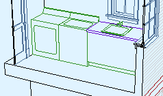
The chimney proper is built from walls and slabs. At the top things tend to get weird, with a lot of zigging back and forth. This object should help with that, as well taking care of ending the flues.

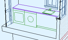
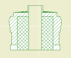
Executive summary: Build up a stack of up to eight stages of masonry. The stages can be offset to each other, and can slant as needed. The flues are cut through the stack. Flues can be arranged automatically or moved around.
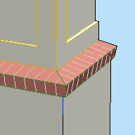
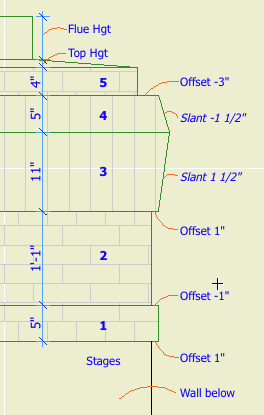
Chimney stages
Stages

You can have up to eight, and you can have none. (Let me know if you need more.) Each stage is turned on by setting its thickness to greater than zero. Stages must be built in order. If a stage has zero thickness, those following it are not available.

Each stage has parameters for Thickness, Offset to Last, Slant, Material, and Section Fill. Offset is the difference in size from the top of the previous stage. (The first stage is offset to the objects length and width, which will match that of the chimney elements below.) Slant allows the stage to get narrower or wider toward the top; positive values increase size, negatives decrease. A slant of zero is vertical.
The first stage should always be offset; if it's flush with the chimney, you should eliminate it and make the chimney (walls or slabs) taller.
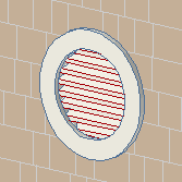
Flues

Quantity between zero and four. I think the zero case would be quite rare, but there it is.

All the flues will use the same Material and Section Fill parameters.

Flue dimensions can Match, or they can be set independently.

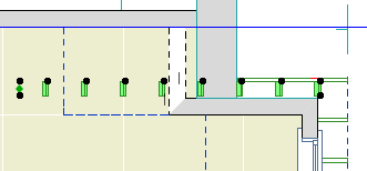
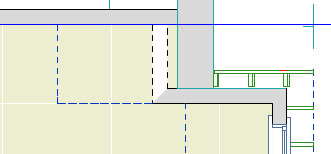
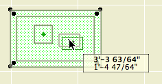
Flue Arrangements: Both Auto arrangements line up the flues down the middle of the chimney. Auto Max spreads the flues as far as possible between the ends of the object, staying within the Minimum Chimney Thickness. Auto Min puts the flues as close together as possible in the middle, with the Minimum Flue Spacing between them. Customize allows you to move the flues around in plan using the editing hotspots.

Flue editing

Note that the object doesn't check if the flues fit; it's up to you to make sure the whole thing is big enough.

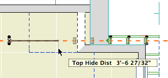
Flue Height Above Chimney is the distance the flues stick out the top.

The Flue Thickness in Section option shows the flue thickness all the way through the chimney. Otherwise, the flues are simply sitting on top of voids cut directly through the chimney parts. You will usually have this parameter off in order to line up better with the flues in the chimney below. As discussed here, it is nigh-impossible for the flue object to show its thickness. If it ever becomes possible, the chimney top will be ready.
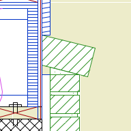
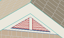
Chimney core
Core

Section only. Obviously. There's a big blob of something, probably CMU, in the center of the chimney, cutting through all the stages except the top one. The Veneer Thickness controls how much of the stages remains on the outside.
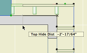
Top

Sloped parging on top of the last stage. The top slopes up to the Top Height, forming a plateau which traces the flue outlines. The top gets its own material and section fill. The top can be on even if all the stages are off.

Related:
Chimney/Fireplace 1: Fireplace in Plan
Chimney/Fireplace 2: Chimney in Plan and 3D
Chimney/Fireplace 3: Flues
Chimney/Fireplace 4: Hearth Structure

« Newer | All Entries | 1 | 2 | 3 | 4 | 5 | 6 | 7 | 8 | 9 | 10 | 11 | 12 | 13 | 14 | 15 | 16 | Older »