These guidelines are current as of Archicad 25.

IFC is a format for exchanging models with data attached between different software. IFC elements are 3D construction elements and objects. IFC has nothing too with plans, annotation, or anything 2D.
The only consultant I have worked with is StructureCo, which is a pseudonym. The type of work is custom residential -- mostly wood members with some steel. This is our first try at this type of coordination.
My goals for the StructureCo collaboration:
• If I can get the beams labeled in the sections, and check that the structural elements fit, I can let them do the framing plans.
• Automatically label elements based on data provided within them, such as ID or profile.
• Let their layer names come through, with an extension.
• Bring in elements with proper classification.
• Avoid creation of attributes other than Complex Profiles.
• Let the consultant do the model 'their way' as much as possible. We try to be low-maintenance teammates.
In other words, let them do some of the work without sacrificing the consistency of our model and annotation process.
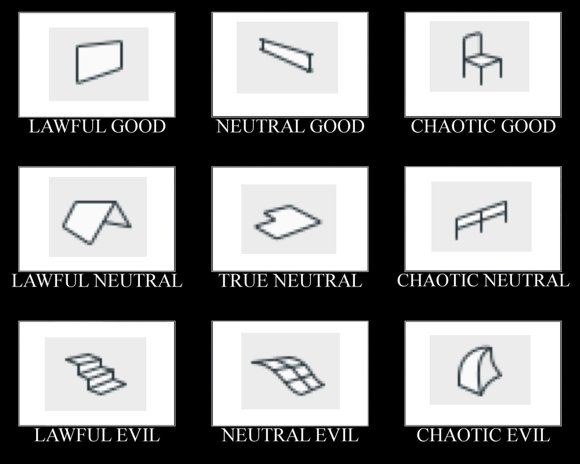
I didn't want to talk this to death. What I like about alignment charts is they are assertive rather than argumentative. You have to just look at them and work out the relationships among the things, and ask yourself if your impressions of the things agree with the author's.
I made this by instinct. The strongest notion I had was that the morph tool is chaotic evil. The second strongest notion was that the mesh tool is a relic and needs to be done over. Then I was on my way.
Having meditated on it a bit, I think this is what the axes mean:
The lawful-chaotic axis runs from standard orderly content to custom content. The good-evil axis runs from user flexibility to user frustration. With that, I will proceed to talk it to death with some comments on each item.
You don't need to use clones to create views, but I recommend them. To review, a clone folder is a viewpoint set such as stories, sections, details, etc., with view settings pre-arranged so that when you make a new story, section, or detail, a new view is automatically created with the correct settings. View settings are easy to mess up and there are a lot of them, and they directly affect output. Better to set up clones in your template, and have all your views perfectly set, even for viewpoints that haven't been born yet.
Some users/managers/template makers eschew clones in favor of placing dummy sections (e.g.) and moving them around as needed. That's OK, especially if your projects are of a consistent scope that you can prepare the template for it. Our projects vary in size a lot, and I like the user-proofing aspect of clones either way.
The only thing I don't like about clones is that they always clone the entire set of viewpoints. We have two clones of the sections: one for building sections at 48 scale, and one for wall sections at 16 scale. Both clones contain all the sections, so we sort the list using the section ID. Building sections are A2 and wall sections are A3, and then in each folder the user has to mentally tune out the sections that shouldn't exist. (And the junk sections, which are never used for output, appear uselessly in both.)
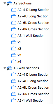
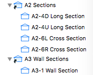
Junk trimmed for brevity
I'd like to see clones that could be filtered by ID, so that only the A2 sections appear in the building sections clone, and only the A3 sections appear in the wall sections, and the junk can be avoided completely.
Element Transfer Settings is a new feature of Archicad 21. It allows the user much greater control over what settings are injected during a syringe operation and/or when favorites are applied. I haven't explored the feature enough yet to be inspired by what it can do, but I think it's going to be helpful.
But I have a problem with the way the feature behaves in projects migrated from Archicad 20. When you open a project in Archicad 21 the first time, a single ETS option is created, Transfer All Settings. As you would guess, every setting in every tool is checked off. This includes settings that didn't transfer in Archicad 20, such as story, ID, and zone name and number. These are the personally annoying results that drew my attention:
• Favorites are set to include the story. So on every story except the home story when the favorite was created, you will get that wonderful dialog box about changes on an unseen story, and then you undo, fix the story, and do it over. (In 20 this just behaved badly and acted like a bug. It works perfectly now once you know what ETS is.)
• ID is included, so if you use unique IDs to schedule elements such as doors and windows, you are going to start to see duplicate IDs (i.e., data loss) from using favorites or the syringe.
• I don't think I've ever eyedropper/syringed a zone, but if I did, I wouldn't want the name and number to transfer, that's crazy.
The old way in Archicad 20 offered some control over these things, so if you wanted to transfer ID via favorite you could, though you couldn't via syringe. (That's really confusing and the new way is better, once you know about it.)
So a migrating user of Archicad 21 is probably going to encounter frustration and data loss, before they even meet the new feature that is responsible. The migration process should have created a safer default ETS option. Note, this is only an issue with migration - the templates have a sensible assortment of options.
I have only made a few ETS options so far, but my default one excludes story, ID, name, number, reference ID, title, and label text content. I have a separate option to transfer label content. And I renamed the bad one to: 'Transfer All Settings BE CAREFUL'.
Graphic overrides are a new feature of Archicad 20. They allow you to choose elements by criteria, and change their appearance attributes. The changes are grouped into combinations which can be saved with views.
Here's how to use Archicad: Build a model, and try to create all the documentation while doing the least amount of non-modeling. If you find yourself drawing something that you have already modeled, it must be because the thing can't be made to present itself in the appropriate way for your documentation. Archicad has always offered methods to help with this. A door can have a complex plan symbol, a simple symbol, or just an opening; it can have a schedule marker or not; or it can be hidden entirely. The same one door appears in 3D and in a schedule. One door, many appearances in documentation. This is unity.
Graphic overrides greatly expand the variety of ways that a single element can be presented. This means it is less likely that you will need to 'draw' an element you have modeled in order to get it to appear correctly in your documentation.
This feature gets at the heart of what Archicad is all about. It will definitely change a lot of working and documentation methods. If it doesn't, you are probably using Archicad wrong.
Since this is a major feature, it is impossible at this early stage to predict everything that will change. But I am getting a sense of what the categories of changes might be.
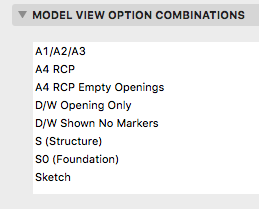
Beginning with Archicad 20, the fills division of Model View Options is obsolete and fills are handled by Graphic Overrides. This enables us to eliminate several combinations that were needed in Archicad 19.
These guidelines are current as of Archicad 19.
This is everything I can think of about libraries management. There have been a lot of changes over the years.
If this was a proper post it would be clearer and have some illustrations. These are just my notes on the process, quite involved for us as you'll see, of migrating a project to AC17/18. Even though 17 was released 18 months ago, we still have projects in earlier versions and I doubt we are alone. IMO, the combination of Building Materials and "Inside/Outside" for walls is the biggest change to AC modeling in my 16 years of using it. It's worse for us because we have a standard of interior wall reference lines, and AC is strongly biased in favor of exterior. No, changing this standard is not feasible.
When an AC16 file is opened in 17/18, building materials are created, several of each kind, based on cut fills of preexisting elements, and maybe favorites and tool settings. You need to sort the Bmats first, to make it easier to sort the composites later.
Sorting the Bmats: In Attribute Manager, open the current template. This has the good Bmats. In the template, here's concrete at ID 4. In the newly opened project, you probably have several concretes. Hopefully one of them has ID 4. Overwrite that one from the template. (In 17, all overwriting is by ID. In 18, you can choose to overwrite by name or ID.) Apply that, and you will get a confirmation that you are modifying the bmat as well as the surface.
Now that you have a good concrete, you can delete the others. You have to do this in the Bmats dialog, not the Attribute Manager. Select all the old concretes (the ones with the strings of numbers), delete and replace with the good new concrete.
Back in Attribute Manager, pick another Bmat that needs to be cleaned up, how about brick. Reopen the template (yes every time) and check that the ID of the template brick matches any one of the project's bricks. If it does, repeat the process above. (Overwrite, delete the others and replace with the good new one.) If it doesn't match, e.g., template brick's ID is taken by Empty Fill ########## in the project, postpone working on brick and choose something else. In the process of cleaning up the other Bmats, template brick's ID will eventually become available.
Keep overwriting and replacing, back and forth between the Attribute Manager and the Bmats dialog, until you have all good Bmats from the template.
Once the Bmats are done, you can do the composites. Some new composites are created, though the old ones remain. Composites are upside down because of the inside/outside thing, so the easiest way is to replace them from the template where possible. (Technically, they aren't upside down yet, but they will be once you flip the walls.) Because the old composites are kept, it's easy to line up the IDs with the template and you might be able to replace them all in one Attribute Manager session. Then in the Composites dialog, delete the items with the long numbers, replacing them with the good ones from the template. Unfortunately, for composites you can only delete them one at a time.
Changes to walls in AC17: They have Inside and Outside faces. The surfaces (formerly materials) are set by these faces, not by the ref line side. The ref line can be inside or outside face. The three surface attributes can take the surfaces of the wall/composite's Bmats, or they can be overridden. In practice they get overridden a lot, and in the overridden state they are just like the three attributes in AC16 and earlier.
This default Bmat/surface/override behavior is suspended when a project is migrated. There is a legacy setting in the Project Preferences for Construction Elements (In AC18 it is under the Legacy tab). It stops the new intersection method from working (the 3 digit number in the Bmat's settings), and also auto-overrides the surface attributes of elements such as walls. So the override button is not available for those settings.
If you turn the the legacy setting off, the override button will come back to life, with the override on. So you should see no changes to surfaces. What will change is the intersection behavior between Bmats. With the legacy setting off, the 3-digit priority takes effect, so you might need to tune those up to get the behavior you expect. One change you must make: The cutting layers need to be set to a high intersection number to prevent them interfering with ordinary elements. For a clear example, turn the legacy setting off, open a section, and take a look at what the site cutting slabs do to the basement walls. I'm using 100 for this intersection number in the templates. It only need apply to section, elevation, and 3D layer combination types.
There is no rush to turn off the legacy setting to keep working as you were. If you are purely migrating the project, i.e., archiving it in the most current version, I would leave the legacy setting on.
GS decided that most people have the ref lines outside, which I guess is true. For us it is false. When you migrate a project, the Inside/Outside setting has to be created from scratch since in does not exist in AC16. All walls are reborn in AC17 set to Outside Face. The ref lines are still inside, and the interior/exterior surfaces are architecturally correct, but it is not sustainable to continue working with this setup.
Even though the appearance is fine, logically it is intolerable. Here is an exterior wall. Its ref line is Outside Face, but that is the interior side of the wall. In the wall's settings, the interior surface (paint) is on the exterior corner icon, and the exterior surface (siding) is on the interior. There is no way to keep this straight going forward, especially if you are accustomed in ref lines inside. Further, those composites you imported assume the ref lines are inside. And, the Outside setting is picked up by the eyedropper. No, we need the walls to say Inside Face.
Fortunately, it can be done, using the Modify Wall Reference Line (MWRL) dialog. It's at Edit -> Reference Line and Plane -> MWRL. Option+W on the keyboard. There are two moves involved: Mirror Walls In Place puts the ref line on the other side while keeping the wall in the same location, though the surfaces flip. Edit Ref Line Location - Inside Face changes the ref line side setting and moves the ref line to the opposite face. In combination, these two moves switch the Inside/Outside setting while keeping the ref line in place (on the interior). Dimensions also stay put. There is one very unfortunate consequence, however, which is that the interior/exterior surfaces are now backwards. So for exterior walls and any others where the two faces differ, you have to change those surface settings manually. This could be anywhere from a minor pain to a huge pain depending on the project.
Wall favorites are also reborn set to Outside Face, so they need to be modified, or you can start over by reloading the favorites from our standard setup.
Some new complex profiles are created, though the old ones remain. Delete the new (##########) ones and replace them with the old ones. I don't know what the deal is here, they seem to be identical.
I think this process is far too cumbersome, considering that Bmats are not that big of a deal to us at the moment. Starting a project in 17/18 is no trouble at all, but this is by far the most complex migration we have seen since at least the death of PlotMaker.
It's fine to say don't migrate and finish the project in 16, except: You now need 17 to create BIMx files; GS won't give you the 16 version. And of course 18 offers the superior CineRender engine. So by staying in 16 you are hobbling yourself in presentation.
Most of the trouble in this migration is caused by the assumption that everyone has ref lines outside. It's because of this that our walls are outside-in, and we need the MWRL maneuver, and we need to manually fix all the exterior wall surfaces, and the composites are upside-down. All GS had to do was ask, when opening a 16 file, if the user's standard is ref lines in or ref lines out. I'm sure GS is correct that ref lines out is the majority, but the decision puts us in a bind.
It's also worth keeping in mind that you should generally migrate projects, and continue to migrate past project archives, because you never know when updates to AC or your OS will leave some of your data inaccessible. GS didn't get to vote on whether AC9 would stop working in OS X 10.7. They (presumably) didn't know AC10 and 11 would break in 10.9, and while they fixed them that time, they certainly didn't have to, because generally only the last two versions are "officially" supported. You need AC10 to open anything older than AC10, and the next major OS could break it for the last time. So you need to migrate and keep migrating; archives that are eight versions behind are not a sound strategy. Too bad it has to be such a pain.
Current migration advice:
All projects should be in 16. Addition projects can proceed in 16 without using the new(ish) renovation setup.
All AC17 projects should be migrated to 18. That migration, thankfully, is NBD.
Projects in schematics or design development should be migrated, full-service, as described here. Perhaps I take on these migrations myself. The more projects in 18, the sooner you don't have to work in two different ways.
Projects in CDs can stay in 16 until they are finished. If you need BIMx or CineRender, save a copy and produce those files there.
That said, I don't object to migrating any project if you have the time and inclination. Personally, I migrate everything because I don't like going back and forth.
Completed projects will be archived in AC18, but without the Bmat/wall-sides process. They open in 18 behaving superficially well, and we will let them stay that way. If we ever need to do real work on the project again (it happens), we will do the real migration then.
First, to review: The New Construction renovation filter has these settings:
Existing: Override
Demolished: Hide
New: Show
In plan, new walls are gray and existing walls are white. Demolished elements are hidden.
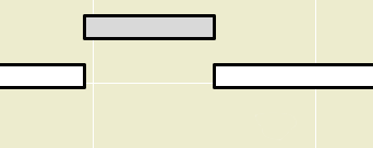
When you demolish an opening in an existing wall, the opening disappears and is replaced by a piece of wall whose status is new.
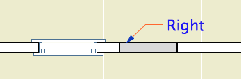
I think this behavior is correct and intuitive. My only quibble is with the lines on either side of the new segment. I'm not convinced the lines should be there at all, and using the cut pen definitely makes them too heavy. But I can overlook it. (Archicad does not consider the difference between element-is-cut and cut-element-meets-air, and I think I have given up waiting for that to change.)
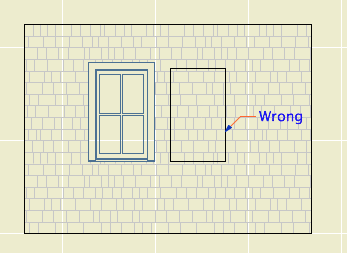
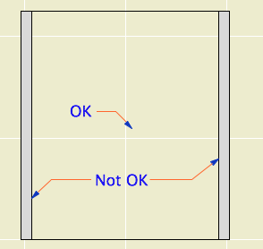
I can't overlook what happens in the elevation. The filled-in portion of wall is explicitly drawn with the shape of the demolished window. There's no way this is OK.
Note: Cut new siding at old window location
• The new wall fragment is based on the existing wall, so it has the same surfaces. Where elements of the same surface meet, the line should disappear. (This is true in AC17. In 16, the material of both sides of the filler piece matches the edge material of the wall. No words.)
• With the surface cleanup rule in place, they would have to create an exception to it, in the belief that it is conventional to show filled-in windows on elevations. We have never done this.
• If I did want to show this condition, it would be dashed and in a lighter pen. These options are not offered. It has nothing to do with the override styles, even though the override setting is what is causing the rectangle to show. The GDL of the demolished window is not involved. The rectangle is drawn with the outline pen of the wall, making it a heavier line weight than the proper windows on the same elevation. Bad graphic, no user control. It couldn't be wronger.
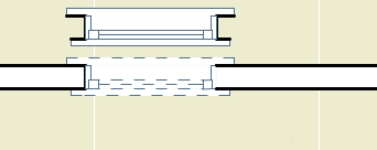
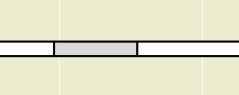
So we need to get rid of it. I stumbled on a way. (N.B.: In the reference guide, there is precisely zero discussion of elevation and hidden line viewpoints in the Renovation section. Once you leave the floor plan you are on your own. Unless you're issuing OpenGL demolition docs, which, um.) In the As Built renovation filter, both existing and new elements are set to show. In the plan, we can't have this because the existing and new look alike. But in the elevation, it means the filled-in wall blends in and there's no rectangle.
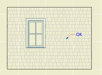
Alright! We just need to use that filter for elevations. Maybe change the name so its purpose is clearer. I don't mind workarounds as long as they work, ya know!
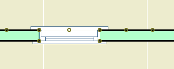
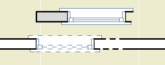
What? Sections? Right, they have cut elements (existing needs to be overridden) and uncut elements (existing needs to match new).
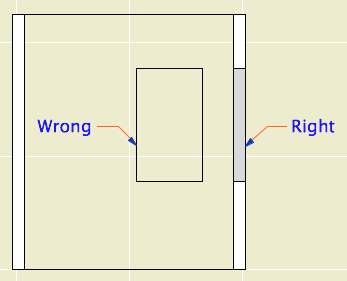
Right like the plan, wrong like the elevation
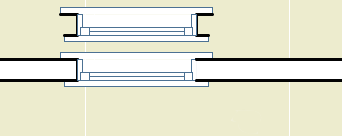
Good elevation, but we can't tell new from existing
It looks like that filter trick doesn't solve it, and I think we've reached the end of the line. Direct demolition of openings just doesn't work. I don't know how they released this feature in this state, and I don't know how they haven't fixed it three versions later. It's really poor.
We will continue to use renovation. But we have to go back to the old method of splitting the wall on both sides of the opening, demolishing the piece, and filling in manually with a piece of new wall. This works reliably as ever and cleans up in all views.
The logic of renovation is that removing an opening involves creating some wall. When I create a wall to meet another wall and their surfaces match, there is no line. That stupid filled-in chunk should do the same thing.
In situations like this, where a plainly wrong graphic is presented as normal, I get the feeling that Graphisoft's strategy is to hope that conventional documents are swept away very soon by BIMx Docs, live cutting planes, and iPad Pros. My concern for "pens" will seem as quaint as a wax seal! I think they underestimate the status quo bias on the average job site. Today, I need drawings that function in the field. The present is sadly non-futuristic sometimes.
That new world, when it comes, is going to have graphical conventions too, and users will always be charged with turning an ever more complex model into visual information that people can use. At the moment there is a disconnect between the information I can attach to the model ("This window is to be removed"), and the tools to convey that information. ("If this is removed why is it showing?") It should be a core competency of Archicad to bridge that gap.
How to Demolish Openings
First the simple case.
Split the wall at both sides of the opening. The split can be right at the opening's ends, or you can allow some slack.
Drag a copy of the wall with the opening. It's less confusing if you drag it away.
Demolish the opening's wall by switching its renovation status to Demolished. When you demolish a wall, openings in the wall are automatically demolished.
Change the copy's status to New, and delete the opening.
Drag the new wall back in place.
The more complicated case is where a new opening will be placed overlapping the demolished opening. In this situation the pair of walls (demolished and new) must be extended to span both openings, so that the new opening is placed entirely within the new wall.
Placing New Openings in Existing Walls
You do not need to split the wall to place new openings in existing walls. Just place them. The new opening will appear as a demolished portion of wall in the demolition plan. As far as I can tell, there are no graphical problems with using this, the intended technique.
We reviewed some things that people were a little sketchy on.
Which libraries should you use
• The current version's Archicad Library, which is located in the Applications folder, at Graphisoft/Archicad [n]. When you migrate a project to a newer version, you might also pick up an Archicad [n-1] Migration Library.
• The current version's Rill Library, which is located on the Carrot at 2 Libraries/Master LIB [n].
• Do not load the Development library, located within the Master Library folders. Objects in there are in an unreliable state from your point of view. They may vanish or turn into something else without notice.
• Do not load the entire Master LIB folder. That would give the Development folder hazard above, as well as potential duplicates from the Archived Items folder.
• When you migrate a project to a new version, change to the matching version of our Rill library. I do not maintain library parts more than one version back for very long. You will soon be out of date.
• If you have missing or duplicate parts, fix them. You should never see the library loading report.
Here is more on library management and what libraries are where.
Projects need to be on the server
If you take a project file elsewhere to work on it, make sure you put the modified version on the server when you return. If you aren't here and someone else needs to access the project, we need to be confident that it is current.
Where is your drawing list
I have seen cover sheets with no drawing list, and the drawing list box is still titled, "Drawing List". This looks dumb and bad. Drawing lists are generally required by permit authorities, and it is bad user experience not to have them.
Linked detail markers
This is an old, very important, core feature of Archicad. Here is a very old post about it. Nothing has changed.
Here I will re-summarize the detail workflow:
• The default settings of the detail tool in the templates are: create new viewpoint (source marker), in reference to the viewpoint, with the layer +Z SE Hide. To draw details based on other viewpoints' content, use the marker Detail Area JM10.
• Place the new marker with the "Create new detail viewpoint" option. This becomes a source marker. Develop the detail content.
• Save a view of the detail in the CDs/A3 Details/ subset.
• Place the view as a drawing in a layout.
• Return to the detail marker and change the reference to the first placed drawing of the viewpoint. (This is generally robust because there is probably only one drawing instance of that detail.) Change the layer of the marker to +Z SE Print.
• If you need to call out the detail from other locations, drag or copy/paste the marker. The new copies will be linked markers in reference to the selected viewpoint, which is the original detail.
• You can use other detail marker objects to refer to details you have developed using the Detail Area. Those would be placed as linked markers to a selected drawing.
• You can move the detail drawing around the set as you like. If you have to move the drawing to a different sheet, drag it in the navigator rather than cut/pasting it. If you cut or delete the drawing, the markers will go bad.
• To call out any placed drawing, use a linked marker in reference to "the selected drawing".
Composite separators should be off for stud walls
For composites representing 2x4 and 2x6 stud walls, the lines showing the drywall and sheathing should be off. At 1/4" scale, they don't read individually and add extra wait to the main wall outline.
• In the composite settings, Use Skin Separator Line should be unchecked.
• In the wall settings, Use Structure's Separator Line should be on.
You Actually Do Have To Split Walls To Demolish Openings
I have much more to say about this.
Keep junk sections junky, and don't have too many
It is very useful to use non-output sections to work on the model. I call these junk sections. They use a simplified marker, a subtle pen color, no names, and IDs of the series x1, x2, ... They are set up in the templates and in the favorites.
Junk sections should never have names like output sections. This makes your Project Map and View Map very confusing. If you have junk sections with real names, fix them.
Never use junk sections for anything important. If you use a junk section to create a detail, or turn one into an output section, then change the pen, marker, and/or name to account for this.
Don't have too many. It is better to have a handful and move them around. Having many sections and elevations will eventually affect file performance. In order to move them around without worry, you need to be confident they are truly junk; see the rules above.
Don't use Up, Down, Left, Right in section or IE output names
Elevations of the exterior should be called Front, Rear, Left, and Right.
Interior elevations, by default, should be named after the room and the compass direction of the elevated wall. Both of these can be automated if you are using zones (for the name) and have Project North set correctly (for the direction).
Up, Down, Left, and Right refer to the plans, not to the building. It looks odd to see a title like "Kitchen Down"; what is that, the floor?
Interior elevation names can be customized if it makes the title clearer. If there is only one elevation of a room, you can just name it after the room. In the kitchen you can name it after the equipment on that side. At a kitchen island, you name them after the things they face, e.g., "Island Facing Sink". For most walls worth elevating, it is evident what is special about them, and beyond the room name the title doesn't add much. It just shouldn't be confusing.
I think the Up, Down, Left, Right idea comes from the IDs we use for building sections. (A2-4R Cross Section looks to the right, A2-4L looks to the left.) These are good, because the help make the name-ID combination unique. But they have nothing to do with output.