What happens if you revive an ancient project and you want use the layout structure of the current template?

The reflected ceiling plan is a universal drawing type that Archicad simply does not handle very well. We took a medium-size step forward in Archicad 11 with addition of the 'Ceiling Plan' model view option for GDL objects. This allows object developers to make objects that draw themselves differently whether the 'Ceiling Plan' or 'Floor Plan' setting is active. But this switch only applies to objects, and beams, slabs, etc. don't know you want a different linetype when they're overhead as opposed to on the floor. Hopefully, this switch will soon apply to all elements, and we will have dedicated attributes for 'Ceiling Line Type', 'Ceiling Pen', and 'Ceiling Cover Fill'. I have wanted this for a while.
In the meantime, the RCP still demands a lot of tracing of modeled elements. It's better than it used to be, but it's still one of the least unified drawings.
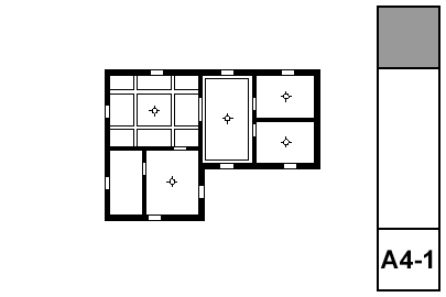
What shows:
• Walls
• Ceiling trim and finishes
• Ceiling fixtures including lights, fans, and mechanical fixtures
• Floor elements, including deck edges, stairs, counters; traced with a dashed line
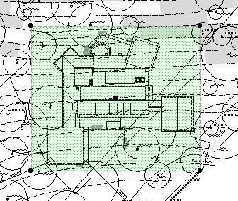
Why? The site plan is generated from the first floor. The roofs are only seen in their entirety on the roof story. The only way to get the roofs on the first floor is to draw (trace, copy/paste, whatever) them. We don't like drawing things. Especially things that can draw themselves, especially things we have to keep checking in on to see if they are drawn properly. We want a top view drawing that maintains itself like any other model view.
There are two ways to do a top view so that it remains live: A plan view from the roof story (like the roof plan itself), or a hidden line top view generated in the 3D window. I think the 3D method is better. The 3D view can show elements of all stories, while the roof plan will use the story settings of individual elements. There's no issue of display order in 3D. A roof plan drawing would have the advantage of generating a little bit quicker, but that's not enough to change my mind.
The templates are set up with a view in the 3D views folder called 'Top View'. You might need to change the scale of this view; obviously it needs to match the scale of the main site plan. The other settings are:
• Layer combination: x Shoot Roof Plan Top View. (Update: I changed the name for clarity.)
• 3D Projection Settings: Top view, azimuth=270 (Camera at bottom).
• 3D Window Settings: Internal Engine, hidden line, vectorial hatching off, shadows off, transparency off.
The trickiest part about the two-drawing approach is aligning the top view with the main site plan. For some reason, we don't get the snap points (midpoints, e.g.) for lines within drawings, so we can't line up a roof edge midpoint with a footprint line midpoint. Fortunately, for most purposes, good enough is good enough. Zoom in and eyeball it. Make it look good. Remember, the dimensions will be to the footprint, which is drawn precisely in the main site plan drawing. If you do need a precisely placed top view, you'll need to place some temporary alignment elements on the first floor.
Make sure the top view's drawing element is set to have a transparent background. The pen set of thew drawing should be Layout 1/8", which turns the heavy lines a little less heavy.
The new templates for Archicad 11 have an improved fill pattern for concrete in section, Concrete Random. I got it from Andy Thomson.
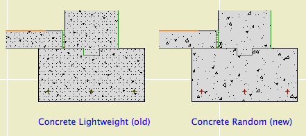
As you can see it has more size variety in the specks and is more random overall.
I've chosen to leave the old fill in place with its attribute ID unchanged. Why. To avoid potential conflicts when merging project stuff that has the old fill.
For new projects, this won't make any difference. All the composites, favorites, and standard details are set up. For running projects, it means some work to deploy the new fill.
So here's a pretty good list of everywhere you have to look to fully modify such a common attribute:
• Slab elements, including 'slab' slabs and footing slabs. In the 3D window, do a Find & Select for slabs of fill 'Concrete Lightweight'.
• Wall elements. In the 3D window, do a Find & Select for walls of fill 'Concrete Lightweight'.
• Other elements: A roof in the role of a ramp? A mesh for a slab sloping to drain?
• Favorites for any of the above need to be redefined.
• Composites for walls and slabs. Favorites with composites don't need to be redefined.
• Fills in drawing windows, primarily details, but including 'Drawing' sections, elevations, and interior elevations. There shouldn't be many of those.
The fills in the Material Symbols and assembly modules are a management responsibility.
It sounds like a lot but it really isn't, and the new fill looks a lot better.
You can use Attribute Manager to get the fill from either of the zTemplate 11 folder's .tpl files. Overwrite, not Append. (It will overwrite 'Concrete Structural', which is even lamer-looking and we never use it.)
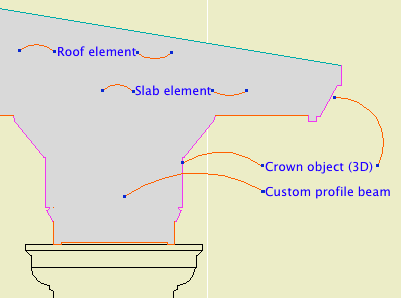
(1) A custom profile for modeling and (2) an object for annotation.
Profile:
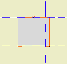
In the profile editor
• The horizontal stretch extents are inside the fascia board reveals. This way, when you adjust the overall width the fascia thickness will be unchanged. Similarly, the vertical stretch extents go from the top to the underside of the soffit, leaving out the reveal.
The custom profile tech only allows you to stretch one dimension horizontally and one vertically. You can exempt parts of the profile from stretching, but you can't stretch them independently. If you want a different reveal depth or fascia thickness, you'll need another profile.
• Profiles can stretched bigger, but not smaller. (I call this a bug, but what do I know.) Any profile you intend to use with varying dimensions needs to match or be *smaller* than the smallest case you have.
• The templates have two profiles, Coffer Beam and Coffer Beam Half. Both are 4" x 2" which should be small enough. The half version has the fascia on only one side and is meant to be placed along a wall.
Remember that profiles are attributes, so they're within the project file, so you can edit them without messing up anybody else. And: You can use Attribute Manager to bring profiles into the current project from the templates.
Here is a sample condition at 1/4" scale, no detail added:
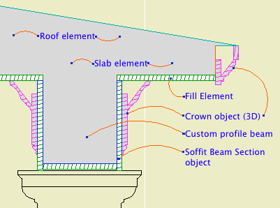
At higher scale, we need to add detail:
Object: Soffit Beam Section JM10
Location: 06 Wood & Plastic / 2D Wood
The object fits within the profile's perimeter.
• Height and width of the object will match that of the beam itself.
• Parameters for Fascia thickness and reveal.
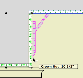
• Crown Hgt sets the point at which the pen switches from the object's cut pen to the Separator Pen. In practice this height should meet the bottom of a crown object placed against the beam, which will maintain the heavy outline.
• The Half option uses one fascia board to work with the half version of the profile.
Commentary:
We build one model. We take views of the model and annotate them as needed. We will take views of the model at various scales. Scale is fundamental to architectural documentation: As we look closer, we see more.
Yet Archicad lacks any meaningful automatic scale sensitivity, except that written into objects by people who want it such as me.
In this example, see how the crown objects draw themselves as empty blobby things at 1/4" scale, but they're detailed shapes with proper fills at higher scales. The roof, slab, and beam elements, not so much. (Archicad library objects, not so much either.)
Since we can't get conventional AC elements to detail themselves according to scale (yet, I hope I hope), we need to build a model that can accommodate the detail we need to add. This is the idea behind something like the Stud Wall Detail object. The wall is empty, and we place the object in the viewpoints that need it.
The soffit detail described here has always been tricky. If you approximate the beam with a rectangular model, it's difficult to manage the reveal without masking. It's easier to add 2D detail than to subtract modeling.
A custom profile allows us to handle the cased beam in the "Empty Fill +" fashion we are accustomed to with walls, roofs, and floor decks.
Automatic titles are not new to 10, but title objects are new, and now that they are objects, we can use them, which is new.
A drawing title is essentially a marker for a drawing element. Like section markers, detail markers, symbol labels, and door/window markers, you choose the title from a popup menu rather than from an object-type browser.
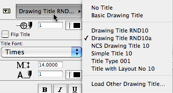
As with all markers, there's no way to restrict the list. It shows all the loaded drawing titles, and it's up to you to pick the right one.
Elevations, sections, site plans, and details should all use automatic titles. Plans are the only drawing which has an object (Plan Title RND10) in the window. PDFs placed for notes ordinarily shouldn't have a title. Scanned details might, it depends.
Since the title and its settings are part of the drawing element's settings, you can change them in groups using the Drawing Manager. (Note: You must have a layout as the frontmost window to do this; otherwise the title tab is grayed out.)
Drawing Title RND10a is very similar to Drawing Title RND9a. There's a couple of 10-specific changes:
• By default, the title uses the name of the drawing (which should come from the name of the view, which should come from the name of the window). You can put in a custom text under the 'Title' tab in the drawing settings dialog.
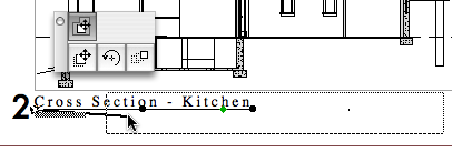
• Titles don't have a length parameter like a regular object. So the Length parameter controls the length. You would normally adjust this graphically:
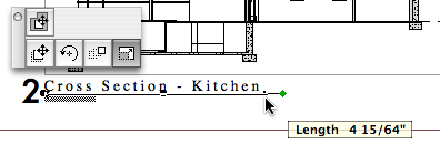
The length still has a minimum equal to the title text length.
Again I have to apologize for issuing a '10a' revision. There was one issue with Drawing Title RND10 that I couldn't fix in place. That title would appear right on the corner by default. The new one appears 3/8" below the corner, which makes it easier to move the title as needed. Note the 'move marker' palette button:
And, full disclosure, I broke the minimum length thing, but now that's fixed.
UPDATE 2007-12-11:
• You can set the Orientation of the title. You can have the title rotate to align with the Drawing (default), the Layout, or a Custom Angle. Use the Layout option to keep the title horizontal when you rotate a drawing. This is optional, and it's not always right. For example, if you rotate a wall section to fit on the sheet, the title should rotate too. I can't think of a purpose for Custom Angle, but it wasn't hard to put in there. If you do ever use it, the angle is graphically editable.
• You can choose a manual scale from a list. Leave the field empty to use the drawing's true scale. This is usually correct. To show no scale text, choose 'blank' from the list. You need to set a manual scale for a scanned detail PDF; now you can choose it from a list.
(Heavily revised for AC10, though still a little clunky.) This is the standard workflow for issuing SK drawings.
Location: 01 General / 5 Title & Layout
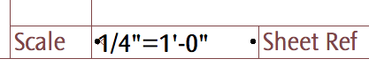
Very, very simple. A text showing a standard scale, which you can choose from a list. The primary use will be placement in the SK layouts' scale field.
Why? I don't like typing scales. And no, it's not easy to get the scale of the placed drawing automatically, though it should be.
Use it for SK addenda.
The templates have a fax transmittal as part of the layout book.
Options
A text object for writing the date.
If Auto Update is on, the date will be read from the system. (Tip: turn it on and then off to get today's date while keeping it from updating by itself tomorrow.) The Year, Month, and Day can be set manually using the pulldowns.
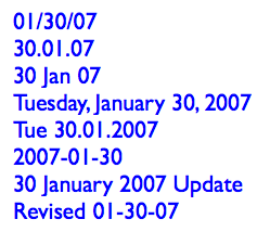
There are a lot of Date Format options. I've tried to cover all the conventions that I know of.
Any of the formats with a separator character will use the character given in Date Separator. You can choose from the list or make something up.
Two-Digit Day will zero-pad single digit days.
Day of Week can be on or off. If it's on, it will be read automatically along with the rest of the Auto Update. It will not fix itself for a manually set date. (It doesn't know the 30th is a Tuesday.) The Format of the day of the week can be long or short. Note that the list will always give the short form. The day of the week can be followed by an arbitrary separator, where the default is a comma.
You can add Leading or Trailing Text.
Text Formatting: All the usual suspects. Font, size. (You can choose mm or points to define the units.) Bold, italic, underline. The object can be anchored by any of the nine typical text block spots, using the Horizontal and Vertical Anchor parameters. You can have a Background Pen and the Outline Pen. Setting either one to zero turns it off. Finally, you can set the Padding between the text and the background/outline polygon. (This uses the same units option as the text size.)
Non-locals who would like to try it out can download it here.