
All Entries | 1 | 2 | 3 | Older »
Here is a most ancient and despised bug in Archicad's wall cleanup behavior.
In most cases, if two surface edges meet whose materials are the same, the line between the surfaces is eliminated.
In our true masonry fireplaces, the hearth support is usually a cantilevered concrete slab. The hearth itself is a separate slab with its top at the level of the finish floor, usually 3/4" above story zero.
This finish slab may vary in thickness, and will often be thicker than the typical finish floor. You want to see this slab in plan; put it on A Fireplace or A Cabs2. The concrete slab will be placed directly below the finish slab. It should go on A Chimney3.
Modeling the hearth structure tends to be a construction documents phase task. When you began modeling the chimney in schematics and/or design development, you might have placed the firebox object at project zero, which was OK then. Once you have the real hearth structure in place, however, you need to lower the firebox to meet the structural slab, not the finish hearth. Make sure you add this adjustment to the height of the firebox object, so the top stays put. The polygon wall surrounding the firebox object also needs to be stretched down to meet the slab. (The wall height can be stretched in section, not so much for the object. LAME.)
The structural slab usually extends all the way through the chimney stack. The core portion of the chimney below should be shortened to meet the bottom of the slab.
The other clashes between the hearth slabs and surrounding elements are solved with solid element operations. Both hearth slabs need to be subtracted from the main joist deck, and the concrete slab may need to be subtracted from the non-core wall below.
To be clear, don't move the joist deck to accommodate the hearth; you need it where it is to complete the ceiling of the story below. But the finish floor should be edited to go around the finish hearth. If there's a floor finish fill, it needs to go around too.
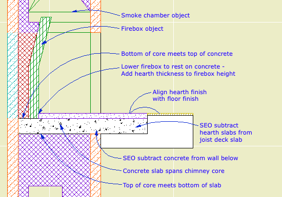
Hearth flush with finish floor
A raised hearth is not much different. The concrete slab will usually be at the level of the joist deck. The finish hearth, the firebox parts, the smoke chamber, and the flue are all raised by whatever distance. You need another slab of core-type stuff, probably CMU, on top of the concrete slab. The front surface of the hearth will be some sort of veneer material, consisting of walls on the A Chimney3 layer.
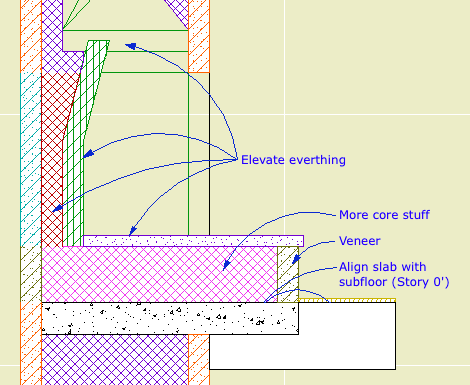
Raised hearth
Chimney/Fireplace 1: Fireplace in Plan
Chimney/Fireplace 2: Chimney in Plan and 3D
Chimney/Fireplace 3: Flues
Chimney/Fireplace 5: Chimney Top JM11
Not for Construction
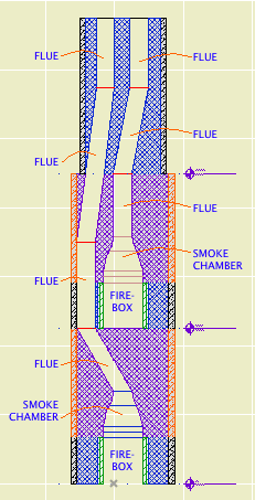
The path of the smoke inside the chimney is created by a series of SEO subtractions using the Smoke Chamber and Flue objects as operators. The targets are whatever elements the objects pass though.
Each firebox has a smoke chamber directly on top of it.
Directly on top of that is a flue object. In a simple chimney where the flue goes straight up, that might be the only one you need. Usually, however, you will need a chain of flue objects to accommodate bends in the flue. The bending is done by offsetting the top of the flue object.
All the smoke chambers and flues should be on the layer A Flue. This layer shows in plan. The flue object has display controls so you can decide how much of a particular segment will show in plan. For a slanted segment, you can choose to show the 'X' at the top or bottom position of the segment. Don't forget about showing objects on stories above and below.
The smoke chamber should be drawn with a white pen such as 60 or 80. Make sure it isn't a thick white pen. (In the 11 templates this is #40.) The smoke chamber can show the 'X' in plan as well.
Like with any vertical modeling, you will find it very helpful to cut a couple of sections through the chimney to line up the flues top to bottom. But: The A Flue layer is set to wireframe by default. You won't see the flues in section unless you switch the layer to solid. The objects should use Air Space as their cut fill to differentiate them from the surrounding masonry material.
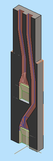
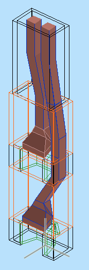
If you show this to a mason he will have a good laugh, but it does allow you to schematically design the chimney and determine if you have enough space for the flues to fit while maintaining allowable slopes. (Which, right, that one piece looks a little stressed.)
Related:
Chimney/Fireplace 1: Fireplace in Plan
Chimney/Fireplace 2: Chimney in Plan and 3D
Chimney/Fireplace 4: Hearth Structure
Chimney/Fireplace 5: Chimney Top JM11
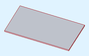
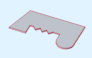
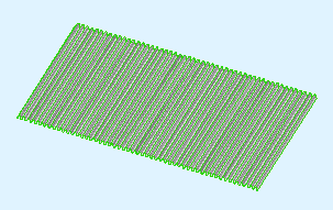
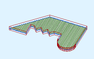
As you know, you don't cut the grade mesh using the building elements. You place slabs in the shape of the holes you need to fit the building.
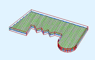
You might find cases where it's more appropriate to use a roof:
Create the roof with the pivot line at one edge. Go to a section and fix the slope graphically, using the slope button.
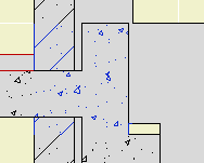
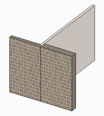
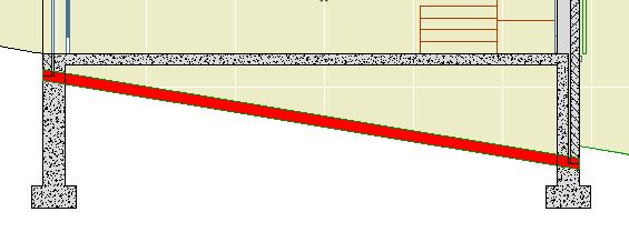
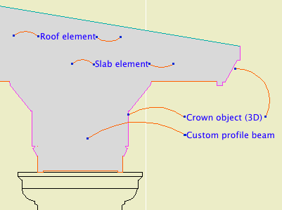
Here's the ordinary elements by themselves. I put in some detail objects for clarity:
The top of the concrete wall is in the right place for the joists, but it's part of a composite with the stone veneer that needs to reach the bottom of the slab. Likewise, the frame part of the upper composite is right, but the stone needs to come down.
There are several ways to solve this with walls and slabs. I'm not going to go into them, except to say they are all rather unpleasant, typically involving 3-5 elements, some of which will be new composites. Sad work, especially when you have to take the whole mess around a corner.
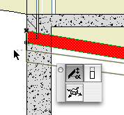
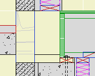
An alternative would be to use fewer elements, get it looking OK-but-not-great, and then use a patch to make it pretty. As you know, you create a patch from existing geometry, and then use 2D editing to force it to look right.
(To be clear, I'm not against patches. They are hacks, but often essential hacks.)
Here's the thing though: If you're going to push fills around to make the condition look right, why not do it in a custom profile? It's still a 2D shortcut, but you end up with a 3D piece you can use wherever you find the condition. It will miter around corners and generally behave like a proper modeling element, displaying correctly no matter where you view it.
A custom profile can be arbitrarily complex, made up of any fills in any shape, and when it's placed it will clean up in section to the like fills it touches. Its surfaces will clean up to like surfaces in elevation.
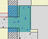
Such a profile could used with a wall or a beam element. Use a 3D-only layer such as A Wall3. It's probably easier to place the wall/beam on the lower story in this case. If you use a wall for the profile, set its Floor Plan Display to 'Overhead All' so it stays transparent.
Conclusion: If you're facing a multi-fill section patch, see if you could use similar fills in a custom profile instead.
(1) A custom profile for modeling and (2) an object for annotation.
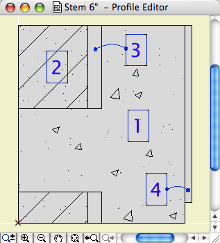
Profile:
In the profile editor
• The horizontal stretch extents are inside the fascia board reveals. This way, when you adjust the overall width the fascia thickness will be unchanged. Similarly, the vertical stretch extents go from the top to the underside of the soffit, leaving out the reveal.
The custom profile tech only allows you to stretch one dimension horizontally and one vertically. You can exempt parts of the profile from stretching, but you can't stretch them independently. If you want a different reveal depth or fascia thickness, you'll need another profile.
• Profiles can stretched bigger, but not smaller. (I call this a bug, but what do I know.) Any profile you intend to use with varying dimensions needs to match or be *smaller* than the smallest case you have.
• The templates have two profiles, Coffer Beam and Coffer Beam Half. Both are 4" x 2" which should be small enough. The half version has the fascia on only one side and is meant to be placed along a wall.
Remember that profiles are attributes, so they're within the project file, so you can edit them without messing up anybody else. And: You can use Attribute Manager to bring profiles into the current project from the templates.
Here is a sample condition at 1/4" scale, no detail added:
At higher scale, we need to add detail:
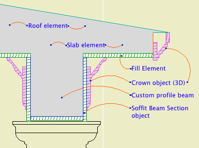
Object: Soffit Beam Section JM10
Location: 06 Wood & Plastic / 2D Wood
The object fits within the profile's perimeter.
• Height and width of the object will match that of the beam itself.
• Parameters for Fascia thickness and reveal.
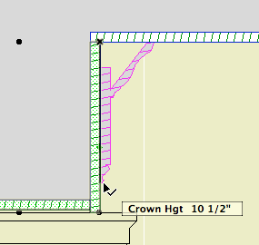
• Crown Hgt sets the point at which the pen switches from the object's cut pen to the Separator Pen. In practice this height should meet the bottom of a crown object placed against the beam, which will maintain the heavy outline.
• The Half option uses one fascia board to work with the half version of the profile.
Commentary:
We build one model. We take views of the model and annotate them as needed. We will take views of the model at various scales. Scale is fundamental to architectural documentation: As we look closer, we see more.
Yet Archicad lacks any meaningful automatic scale sensitivity, except that written into objects by people who want it such as me.
In this example, see how the crown objects draw themselves as empty blobby things at 1/4" scale, but they're detailed shapes with proper fills at higher scales. The roof, slab, and beam elements, not so much. (Archicad library objects, not so much either.)
Since we can't get conventional AC elements to detail themselves according to scale (yet, I hope I hope), we need to build a model that can accommodate the detail we need to add. This is the idea behind something like the Stud Wall Detail object. The wall is empty, and we place the object in the viewpoints that need it.
The soffit detail described here has always been tricky. If you approximate the beam with a rectangular model, it's difficult to manage the reveal without masking. It's easier to add 2D detail than to subtract modeling.
A custom profile allows us to handle the cased beam in the "Empty Fill +" fashion we are accustomed to with walls, roofs, and floor decks.
Prettier version from AC20 here.
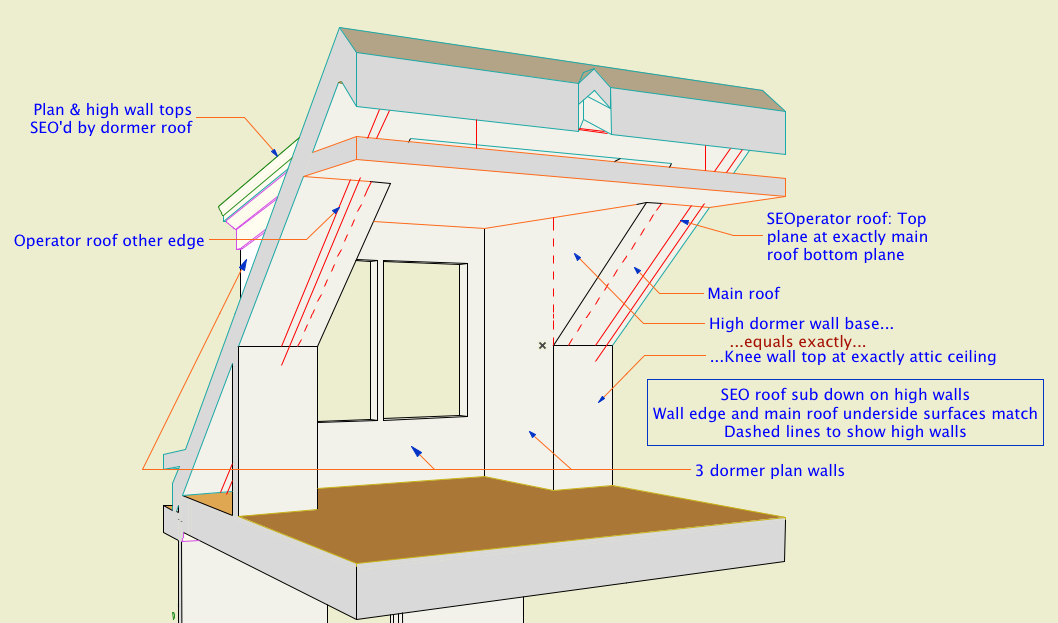
Attic dormers have long been a black art in AC modeling. The 3D cleanup improvements in AC10 make their behavior much more predictable. In order to see these improvements, make sure this box is checked in Preferences -> Construction Elements:
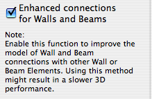
I can't say I've observed a performance hit in using this. No matter, it needs to be on.
About 60-80% of this post is missing.
This is a complicated topic. No, it's not a complicated topic, it leads to complicated topics. If I can decide how to limit the discussion, it isn't complicated at all. This is the dilemma with a lot of powerful AC features. I'd like you to grasp the whole puzzling, quirky thing, but I'd also like you to get your work done. I can't decide whether to make you work for it or just give you the answer.
Well, the Floor plan cut plane is way over on the quirk end of the curve, so it's easy to decide this time: Here's the answer. I'm leaving out a lot. UPDATE: Here's more if you want it.
So. Roofs in Plan.
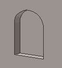
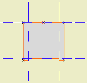
A rectangular or arched shape for subtracting niches into walls.
If the Arch Height is zero, the top is flat. The Wall Pen draws a heavy line around the back of the niche, to match the weight of the wall's contour.
The side with the center node should go along the edge of the wall. That side is drawn with the object's pen.
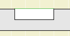
The idea is to SEO subtract the object from the wall, as discussed here. You can use a window to cut a niche, but the subtraction gives you better display control.
You would typically place the object on the layer X SEO Show2. This is the layer for SEO operators that show in plan only. (In 3D views, you would see the niche, but not the operator itself.)
You might need to bring the object forward to make sure it masks the wall. The parameter Edge Nudge helps make sure the lighter edge line of the object covers the heavier wall contour line underneath. Turn on True Line Weights to check it, and increase the nudge as needed.
Download (AC10)
All Entries | 1 | 2 | 3 | Older »