
This started, as so many things do, with making a symbol fill for a tile pattern. A challenge of symbol fills is they need to tile (left and right meet, top and bottom meet, invisibly).
You can make new grid, running bond, and herringbone fill patterns by duplicating the extant ones and changing the dims. Anything more complex, you need to draw and work out the tiling.
That's just the fill pattern, which is vectorial, meaning you can use it in plan and surface fills in elevation. But you are on your own in 3D (OpenGL, BIMx). If you are delivering BIMx, you need to keep your textures in sync with your fills. Here is a simple way to do that.
Location: 01 General / 1 Graphic Symbols

The shapes are square, rectangle, triangle, circle, ellipse, oval, diamond, hexagon, pointed box, and roundrect. The roundrect has authentic iOS proportions.
The rectangle, oval, hexagon, and roundrect will elongate to accommodate the text, if the Stretch for Text parameter is on. The square will turn into a rectangle.
The Height parameter refers to the vertical dimension. The Length Factor parameter is multiplied by the height to get the length of the rectangle, ellipse, oval, and roundrect shapes. If Stretch for Text is on, the length is overridden by the text length.
The text, by default, is the global ID of the object. You can also choose to enter a custom text.
The size of the text can be set by points, millimeters, or as a fraction of the shape height. All these parameters are hooked together, so when you switch among them the actual height stays the same.
There is a value list for the font, and you can enter any font name. The text can be shown bold, italic, underlined, or any combination.
The Mask parameter will make the shape opaque white, using the 'Solid' Fill and White Pen parameters.
The Shape Label is simply a label version of the same thing. When placed as an associated label, the ID displayed is that of the labeled element. Placed independently, you need custom text.
Location: 14 Conveying Systems /
This is a hydraulic residential elevator based on a product line of a real company. Since I don't know how they feel about me 'using' their 'IP', I'm not saying who it is at this time. You could probably figure it out.
Because it's a real product line, there are limited size and configuration options. Under Cab Size there are three. Under Door Configuration there are various. Some of the door configurations offer the option to have the door hinge from the 'Track' side of the elevator or the 'Opposite' side. If this parameter doesn't apply, it is hidden.
You can choose the configuration visually under the 'Configurations' interface tab.
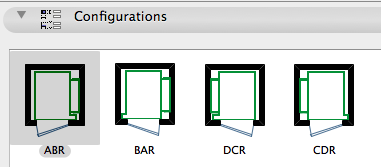
There is a read-only Configuration Code which is generated from the Door Configuration and the Hinge Side. This is from the product catalog.
I have provided a Standard Sizes parameter which locks the length and width to the catalog data. I wouldn't turn this off; I would rather know how big the real equipment is. The only case where I would turn it off is where I was using another manufacturer and the configurations were similar but the exact dimensions were different. Anyway, it's stretchable in principle, but the default is to be locked to the standard sizes. Turn this switch off and stretch to any impossible shape you want, YMMV.
Place the object on the bottom story of the elevator's true extent. Show the object on All Stories. Set the object's Stories Served parameter to reflect the number of actual stories the elevator will serve. The 2D symbol will not be shown above or below this range. (Though (Archicad fail) the object will still be selectable via Select All on stories where it is not visible.) The wall track which supports the cab will automatically extend through all but the top story being served by the elevator. The top story is covered by the value in the Top Rail Height parameter. This value should be roughly the top story's ceiling height. (I found in most cases that the track was too tall if it ran the whole top story.)
The Raise Cab parameter determines how many stories the cab will be raised in 3D from the home (bottom) story. This would only matter if you cut a section through the elevator shaft, and frankly it wouldn't matter much even then.
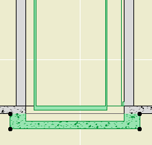
Pit.
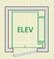
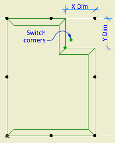
In plan, it looks like an elevator. The length and width dimensions are based on the finished dimensions of the shaft. The text bit should center in the car and it can be customized if "ELEV" doesn't suit you. There is a red (pen 10) line at the center of the door(s), and nodes at the edges of the doors. The door is not part of the object; you need to place a door in a wall normally. There are also hotspots at the center of the track and at the centerlines of the required structure for the track.
The associated pump equipment is a separate object, Elevator Equipment JM16. I also have a call box symbol for the electrical plan, Elevator Call Switch JM16.
Download (AC16)
Location: 01 General / 1 Graphic Symbols
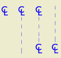
This is your basic CL symbol, since most fonts don't have it. You can change the font and size, and apply bold formatting. It's is an update to CenterLine Sym JM9, which it replaces. It should be on BIMcomponents soon, or you can download it here. I've added two features based on community feedback.
First is the option to show a line in addition to the symbol. If the line is shown, you have the option of repeating the CL symbol at the other end.
Update: If the line is shown and the symbol at the end is on, the symbol at the start can be turned off. In this way you can have the line pointing up from the symbol.
Second, I saw Jakub Chruscinski's version of my old symbol on BIMcomponents, which includes a complete font list in the text options. I'm offering the complete list as an option since it seems like something people like, but it defaults to off. I prefer to restrict the list to our standard fonts.
The default font is Arial in the version I am sharing, but the sublime font in the preview is Gill Sans, which is what we use in practice.
Wonkish: The symbol code consists of two text blocks whose alignment is set using X and Y coordinate offsets with absurd precision (0.0001"). Not all fonts will look right automatically. To get an arbitrary font to look good, you might need to open the 2D script and modify the offsets.
Placement tip: Set the object to insert by the top or bottom hotspot, and use the Rotated geometry method of the object tool.
Download (AC16)
Download (AC11)
Two tweaks to the Railing JM9 object.
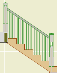
Another one for the well-under-4KB* series...
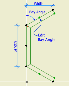
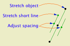
The length of the object is the length of the long line. The length of the short line is set by the Short Line Factor parameter. You can adjust this factor graphically. The spacing of the lines is controlled by the Spacing parameter. Also graphi-justable.
This is a good one to place with the rotate and stretch geometry method (fourth button). With this method I had an intermittent glitchy behavior where the object would appear offset from my clicks, but I couldn't reproduce it.
I wanted to add this symbol to our doors and windows directly, but I don't think it's possible to force the lines to tilt rightward in every case, once you factor in the orientation of the door and the viewpoint and all that.
Download (AC11)
* Until you add the preview image.
Converting 2D elements for use in 3D.
Any 3D element(s) can be saved as an object with the Save Project As... menu command. (In Archicad 11, Save 3D Model As...) This technique is known as 'slabifying' since such models are often built from slabs. Objects saved in this way are dumb (not parametric), but it's still a useful trick.
2D elements can't be saved this way, because they never appear in the 3D window, where 3D object saving takes place. Despite the fact that GDL contains commands for 'flat' shapes in 3D, including LIN_ (a line) and PLANE (not a joinery implement). But there is a workaround for 'slabifying lines'. When you open a 2D DWG as an object, 2D lines are created as LIN_ statements in the 3D script. When you place the object in the model, you get the 2D geometry in 3D.
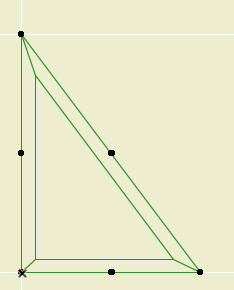
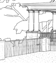
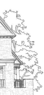
It's that simple at it's simplest, but real world applications need some tweaking. In this example, I'm converting an Archicad library 2D tree elevation symbol so I can use it in a sketch render image. Other applications might be a complex ornament in a hidden line elevation, or a busy glazing design placed in front of a conventional window.

Materials for rind, flesh, and stem. Expression can be happy or sad. I've had this for nine years; I finally took the inline material definitions out.
Download (AC11)
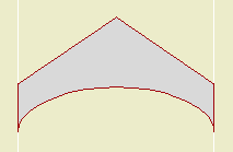
I added an option for an elliptical curve. Original and download link here.