On Land

Environment Information
At Rill Architects we run ArchiCAD on macOS. If you work at Rill, this is your stuff. If you don't, but you work in ArchiCAD, you may find something interesting. Anybody else, I don't know.
RSS
Standards Archive

« Newer | All Entries | 1 | 2 | 3 | 4 | 5 | 6 | 7 | 8 | 9 | 10 | Older »

Current naming standards. Still very boring.

These rules aren't set in stone, but if we all stay near the rules we all stay near each other. Like all standards, they work most of the time. When a situation is addressed by the standards, you can save your creativity for the projects.

More»

Carrot
All the server libraries are in a volume called "2 Libraries", whose icon is a carrot which predates OS X and looks it, and we call the libraries volume the carrot. This is what's there:

BIM Server Libraries. Copies of our standard libraries for use in Teamwork projects.

Library Container Files. An LCF is a compressed archive of a library. It loads very fast and can't be messed up, so it's good for taking projects on the road assuming you don't need to modify standard parts. I try to update the LCF of our current versions' library (13 and 16 at the moment) on a weekly basis. But I might forget, and I certainly modify objects throughout the week, so if you need the LCF you should make sure it's up to date.

Master LIB [n]. Where n is between 7 and 20. The Master folder contains the current "1 Rill LIB[n]" folder, which is standard library that must be loaded for all current projects. It also contains a "Development" folder, which should generally not be loaded; things in there are either broken, unfinished, or otherwise unworthy.

When we start using a new version of Archicad, I copy the entire Master LIB folder and give it the new number. When you switch a project to a new version, you should also change to the newer Master LIB. It will be virtually identical to begin with, but over time the old versions will fall behind. I generally only treat the newest Master LIB as "live" for the purposes of new development and bug-fixing. Back-saving objects, unlike PLN files, is nearly prohibitive in its awkwardness.

Other LIBs. Just what it says. Old project libraries from the pre-embedded days. Old Archicad libraries. (I've lost the 5.1, but we still have the 6.0.) Extracted versions of recent/current Archicad libraries. (Archicad libraries are LCF files. If you want to search them using the Finder, they need to be extracted.)

Alphabetical by name of thing. Please suggest improvements and additions. Many things have changed, many have stayed the same. Layer theory hasn't changed much. Current as of 16, and I'm not anticipating big differences in 17.

Big table below the fold.

More»

Sheet A1-1
• What Shows. Full height walls. Counters, appliances, and plumbing fixtures. Stairs, decks, driveways, floor finish fills. Stair and deck railings. Most roofs. Overhead elements including beams, ceiling lines, and roof overhangs. Room names, preferably in the form of zone stamps. Dimensions. Centerline markers. Names of cabinetry elements ('Bench'). Floor elevations. Markers for sections, elevations, interior elevations, plan enlargements, wall sections, and details. Door and window tags.

• Wall Cleanup.
Plan layer combinations should have different intersection codes for plan and 3D walls. (E.g., A Wall Ext has '1', A Wall3 has '2'.) This eliminates gaps where visible and invisible walls meet.

Wall cleanup has improved greatly over the years, but can still be tricky for complex intersections. Use a patch if you must.

• Display Order.
(Front, back, etc.) Use display order to to make overlapping elements stack correctly. In order for elements to mask elements behind them, they need a fill with a background pen. If you don't want a fill pattern, use 'Empty Fill'.

Generally, annotations should be all the way in front so they aren't obscured by anything. Walls should in front of everything except annotations. Beyond that, you have to pay attention. Counters in front of floor fills, soffit lines in front of counters, stair railings in front of treads, etc.

• Pens.
More on pens here. Walls are 5-weight (usually 15). Edges (Counters, stairs) are 2-weight. Dashed overhead elements are 2-weight. Appliances, plumbing fixtures, and other such objects are 2-weight. Floor finishes are 150. The background pen of construction elements is 50, and existing construction elements are overridden by pen 91.

A note on composites: Contour, separator, and background pens should set correctly in the composites. Walls in plan should be set to use the composites' pens. Stud wall composites should have the separator lines hidden; that is a composite setting, not a wall setting.

• Floor Finishes. Either: 1) Fills on F Floor Fin2. 2) Slabs with a cover fill on F Floor Fin2. 3) Cover fills on the zones. In practice #1 is most common.

• Dimensions. Here. For small rooms, consider enlarged plans and put the dimensions there.

Roundup of issues with daily shutdown, data backup, and power failures.

More»

In Archicad terminology, a marker is a special object that has a subordinate relationship to another element, representing the element and/or saying something about it. Viewpoint markers represent viewpoints in project windows. Each viewpoint type has its own marker objects. There are default markers for each one in the Archicad library, but we (as usual) use customized stuff. Each marker is dedicated to a viewpoint, but all the markers have a lot of parameters in common. Here I will lay out those similarities, as well as the special features of each marker, while making sure we're clear on the correct marker for each viewpoint type.

More»

Executive summary: A new layer for elements in layouts and in the title block worksheets. There should be no elements on the Archicad layer.

AC Layer
The Archicad layer is Archicad's own layer. It can't be deleted, hidden, or locked. Some layer then! Rare is the project element that should always show. These limitations make the Archicad layer approximately useless, and it is widely recommended that it not be used. That said, we have used it for a long time for a handful of always-showing cases:

• The title block object and other stuff in its detail/worksheet window
• Drawing elements on layouts starting in AC10
• Master layout drawings and annotation elements

And it's never given us any trouble, but.

The concrete reason to forswear use of the Archicad layer is that it interferes with Teamwork. The only way to have the Archicad layer in your workspace is to have 'exclusive access' to the project, which is inconvenient in a real shared workflow. It's true that we don't use Teamwork much, but you never know.

Rather than confront the question under deadline pressure some time in the future, I'm changing the standards and templates now to include a layer for 'Layout' elements. This layer, +Z Layout, holds any element placed directly on a layout, including drawing elements, texts, PDFs, etc. It is also the layer for the title block object and anything else within the title block worksheets. The layer is visible and unlocked in all layer combinations except 0 Working Model.

Once all that always-showing stuff is placed on a regular layer that could potentially be hidden, you might wonder how to make sure it always shows anyway. The layout environment actually has its own layer settings, which are maintained simultaneously with the model window layers. Changing the layer settings of one does not affect the other, thank goodness. The templates are set up with the +Z Layout visible in the layouts. As long as you leave it alone, it will always show. If you do hide it, probably by accident, and WOW you'll know right away when everything vanishes, turn it back on. Layout layers are unaffected by view changes. This should be a set-it-forget-it situation.

Some people use multiple layers to turn layout elements on and off, but I don't see the advantage of that for us at the moment. One concern would be that layout layers can't be saved, with views or otherwise, so the user must remember to manage the layers before publication. I would be inclined to handle such visibility control in the title block worksheets. Here is some AC-Talk discussion.

The other advantage of using this standard is that the Archicad layer rule is much simpler: Don't use it, full stop.

Template changes:
• New layer +Z Layout. Show in all combos except Working Model.
• All title block worksheet elements to the new layer. Use F&S for all elements on AC layer, then Edit Selection Set to change.
• Set layer environment layers to combo xxAll, which shows everything.
• All master layout elements to the new layer. On each master, use F&S and ESS as above.
• All drawing elements on regular layout to the new layer. In Drawing Manager, sort by Placed To, highlight all non-master drawings, change layer in settings.
• Change default layer of Drawing tool.
• Redefine Drawing tool favorites with the new layer.
• Save favorites.

MVOlist
Model View Options, formerly known as Display Options, can be organized into combinations, kind of like layers, and MVO combinations can be saved with views. Naturally, this is all set up in the templates. MVOs are completely separate from On-screen View Options, which are screen-only and do not affect output.

The MVO dialog has three divisions. Options for Construction Elements concerns the display of real things, including openings, columns, beams, and markers. Options for Fills and Zones concerns how different categories of fills are displayed; turning cover fills on and off, e.g. Options for GDL Objects has only one item at the moment, the beloved Story Viewpoint Type, also known as the ceiling switch.

The keyboard shortcut to open the dialog is Cmd+9. I think the MVO dialog is pretty good about previewing the effects of most of the controls.

Rather than describe each combination, or heaven forbid build a table, I'll describe the A1/A2/A3 combination, then how the others differ.

More»

Site plan fragment
What Shows

Note, November 10, 2017: Anywhere you see the layer +C Site Annotation, you can use the layer +C Site Note if the current project doesn't have the annotation layer. (This layer is quite new as of this update.) The difference is not important unless the site is being shared among multiple projects. If the site is shared, the annotations layer is for permanent data about the site, such as north direction, survey dims, and topo labels. Notes specific to the project go on +C Site Note.

• General. The site plan is generated from the First Floor story. The 3D grade mesh is not shown because its pen and linetype options are too limited.

• Property boundary with metes and bounds. For the boundary, use an empty fill. (Only a fill can report its area, and you'll need the property area for the project information.) If north is set correctly and the boundary is precisely drawn, you can use and object for the metes and bounds, Survey Dim RND9, located in Graphic Symbols. Layers: C Site2 for the boundary, and +C Site Annotation for the text.

• North arrow object. North Arrow JAM9, located in Graphic Symbols. If north is set correctly, you can turn on the 'Use Project North' parameter. Layer: +C Site Annotation

• Setbacks. Layer: C Site2 Use lines, arcs, or polylines. Setbacks should be labeled 'BRL' (building restriction line). Special restrictions can be labeled more specifically; 'Conservation Easement', for example. Layers: C Site2 for the lines, and +C Site Annotation for the text.

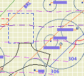
• Topographic survey contours. If available. Use splines. Don't use lines, polylines or arcs. If you have lots of little segments, the dashed lines will never look right. Typically, we will get contours at two-foot intervals. The sea-level elevation of each contour should be called out, unless the contours are very closely spaced. In these cases, labeling only the ten-foot contours is OK. Layers: C Topo Existing and New for the splines, and +C Site Annotation for the text.

For boundary, setback, and topo text blocks, pay attention to the anchor point. This will help the blocks stay in position if you do multiple site plans at different scales.

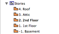
• Building footprint. Layer: +C Footprint.N The footprint is the outline of the building as it meets grade. You will probably use the basement plan to get it. With the Site Plan layer combination active, show the A Wall Ext and S Wall2 layers. Trace the wall outlines with a polyline. You can show the basement story as trace (FKA ghost), or draw the polyline on the basement story and cut/paste it to the first floor.

Show dimensions from the footprint to the property boundary at key locations. For an addition project, the addition portion of the footprint should be filled with a diagonal pattern.

• Trees. If available. Use the object Tree JM10, located in 02 Site / Trees. Don't show removed trees unless you need to. Layers: L Tree2 or L Tree A. Trees on the 'A' layer will also show in the architectural plan. If you have modeled trees, you can place them on these layers or use L Tree3 to hide them in plans.

• Top view of building. This can be a roof plan or a 3D top view. This is a separate drawing overlaid on the site plan drawing.

• Additional building-related 2D elements. Anything you can't get to cooperate with the top view drawing can be drawn separately. Layer: +C House Line.

• Driveway. The layer L Drive2 shows in the site plan layer combinations. If you find that showing this driveway conflicts with the site plan somehow, you can modify the layer combination to hide it, and then redraw it with lines, arcs, and polylines on the C Site2 layer.

• Street. Layer: +C Site2 Use lines, arcs, or polylines.

• Notes. Label the major site and project elements. These are, at least, the existing house and addition, the driveway, pools, large terraces, septic fields. Layer: +C Site Note.

Line Types

• Boundary: Property Dot-dash
• Setbacks: BRL long dash
• 2' contour: Dense dashed
• 10' contour: Long Dashed
• Driveway and street: Solid
• Footprint: Dense Dashed

Fonts

The usual, but to review: Lucida Sans for notes. Tahoma for dimensions including boundary data. The street name looks nice with a serif font; use Times.

Now we have some standard details, in the form of module files, which you can drop into whatever projects might appreciate them. They are located at 3 Resources / AC / External References / Standard Details. These are distinct from the Assembly Type details, which specify the components of walls, roofs, slabs, etc.

I will define a standard detail as a building condition always done in a certain way, independent of superficial architectural characteristics. For example, a brick window header will always be flashed with the same technique, regardless of the size or color of brick, the joint finish, or the shape of the brickmould. Those architectural specifications would be noted in other details and/or in the specs. Further, standard details represent CYA-type technical matters that we want to be sure not to forget, so the easier to drop them in the better.

The first wave of these details concerns the heads, jambs, and sills of openings (doors and windows) in walls finished with wood siding, stone, and brick.

How to use them

Create an independent detail window. Give it a descriptive name such as 'Typ Brick Window Head'. I like to use the ID field to keep the standard details separate from the 'real' details, so I would use an ID like 'Standard01'.

You can either merge or hotlink the desired module into this new detail window. Merge is essentially a paste operation, and the drawing elements will simply appear in the window and act normally.

Hotlinking maintains a live connection to the module file. If the module ever changes, you would get a notice to update it upon opening the file. Elements of hotlinked modules cannot be edited; the whole thing will act like a big locked group. (Module elements' nodes are square donuts instead of round.)

Which way is right. I will say merge in this case. As a 'Standard' detail, it shouldn't change often, and having fewer external references simplifies taking the project off-network.

Create a view of the detail window and drop it on a detail layout. Rinse and repeat.

More info

Don't be distracted by the Standard Details.PLN file in that External References folder. The project file is the administrative resource for generating the module files. Here is a summary of my detail method as it relates to the assembly types. Here is the really sick module generation method, which has nothing to do with the end user. 'Sick' can mean 'gross' or 'cool'.

Please let me know immediately if you encounter a module with multiple stories. How will you know? Such a module will not merge into a detail (or any non-plan) window, and you will get a warning to that effect. If you try the sensible workaround of merging the module into the plan window and then moving it, you will eventually notice multiple empty stories added to your project.

Both of these outcomes are sick in the uncool way.

This problem started in AC11, when it became possible to save multi-story modules. (Previously, if you wanted a three-story module, you needed three one-story modules.) This feature has a crippling bug that was reported in early beta, yet remains unfixed. When you publish a module from a multi-story project, you have a choice of what stories to publish: All, Current, or a range. It doesn't work. When you attempt to publish a single-story module, you get a module with all the stories of the parent project, with the content of only one story, the one that was 'current'.

So, after cool-sick publishing the modules, I have to gross-sick open each one of them and delete the extra stories. Of course, some day I will tune up a detail and re-publish it and then forget to fix it, and you will be sad when you try to merge it, and then you will tell me.

I would like to take this opportunity to express my great displeasure with Graphisoft's current quality assurance standards. This is a major bug in a medium-size new feature. They have known about it for months. They have released four patches to the shipping version on top of a number of beta versions. This bug impairs the ability of serious firms to use Archicad at a high level. It wastes your time and mine. It adds to the apprehension about future releases and how long they, in turn, will take to stop messing up our workflows, if ever. Archicad 10 still has what I consider show-stopping bugs, but it will never be patched again.

It is infuriating today and worrisome for the future.

Every viewpoint has a name and an ID. The name is important and is often used for output. The ID is never used for output, but wherever possible we use the ID to help organize the project map and view map.

Info Box name/ID
For viewpoints with with a marker, the name and ID appear in the Info Box and settings dialog. This applies to section, elevations, details, and interior elevations.

Properties in Navigator
For all viewpoints, the name and ID appear at the bottom of the Navigator under the Properties heading. Viewpoints with fixed IDs, such as stories, will have the ID field in gray.

The behavior of IDs varies among the viewpoint types, so here's a cheat sheet.

Story IDs
Stories have unique, fixed IDs based on the order of stories. They are ugly. We ignore them.

Section IDs
Section and Elevation IDs are created by the user, and they need not be unique, but the name/ID combination must be. (If you try to create a section/elevation with an identical name and ID, AC will automatically append a number to the ID.) Sections and elevations should have an ID roughly corresponding to their sheet number. Building elevations and sections get A2-1, A2-2, etc., and wall sections get A3-1, A3-2, etc. For sections, add a letter to indicate the direction the section is facing. Don't put the direction in the name. For 'Junk' sections, used for modeling support and not for output, the ID should be xn where n is a number. Junk sections x1 through x4 are placed in the template. (Yes, junk sections should usually be sections, not elevations.) So you end up with a section list of output viewpoints at the top, followed by all the junk.

Interiors IDs
Interior Elevation IDs should start with A5. I like to use the ID to sort the interiors by story: Basement is A5-0, first floor is A5-1, etc. Like the sections and elevations, the actual output sheet may differ. The sorting is to help you know where to look in the view map.

Detail IDs
Detail IDs need not be unique. (In AC10 and earlier, they had to be.) Still, it's a good habit to make them distinctive. I find it helpful to use the detail ID to give the 'category' of detail. For example, a bunch of eave details will have IDs of Eave01, Eave02, etc. The assembly type details have Type01, Type02, etc. Structure detail IDs start with S_ followed by a number. For all details, the name should be presentable for the automatic drawing title.

Worksheet IDs
Worksheets are a new, mostly redundant viewpoint type in AC11. We could easily live without them, but since they exist, we park all the straggly non-detail drawing things there. There aren't enough worksheets in a typical project to worry about sorting the list, so I recommend leaving the ID blank and just using the name.

The primary Schedules have an ID to sort them to the top of the menus. Incidental schedules don't need IDs. This may change.

Cameras and paths have unique IDs that can't be changed.

Summary: Viewpoint IDs are not used for output, so use them to help sort the lists. Names are used for output: Use the name you want to see on the paper.

The IDs that do matter for output are those of the layout book items; subsets, layouts, and drawings.

Drawing IDs are usually generated by the layout, either by the grid or the order of drawings in the layout book tree.

Layout IDs are usually generated by the subset.

Subset IDs are set by the user, and the subset ID becomes part of the layout ID.

Views also have IDs, but they should typically inherit the viewpoints' IDs, so the lists will appear the same to us. All view IDs can be customized or set to 'None', but you can usually just leave them be. In the templates, I have deleted all the IDs for story (plan) views, because stuff like "-1. Basement" looks idiotic.

Standard pens updated for AC11.

Changing the pens is a pain, and it's potentially disruptive. I try to avoid it. With this update, I'm trying to minimize disruption while building a system that can adapt in the future. It should hold us for a while.

More»

« Newer | All Entries | 1 | 2 | 3 | 4 | 5 | 6 | 7 | 8 | 9 | 10 | Older »