Original here.

Original here.

I tweaked the Shape Tag object so you could have a masking fill within the polygon.
The intent is to show a solid white fill. To ensure wide compatibility, I've provided parameters for the fill and the white pen. Non-locals may want/need to change the defaults to their preferred solid fill and white pen.
Location: 06 Wood & Plastic
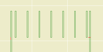
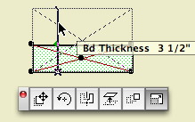
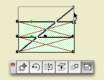
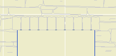
A beam, or any other ceiling element, should be shown dashed in the architectural plan, because it's overhead. That same beam needs to be shown solid in the reflected ceiling plan, because then you're upside down looking straight at it. Using a conventional beam element, you would draw it with a dashed line in plan. But you can't show the same element in the RCP, because you can't make the beam draw itself solid. So you trace the beams with lines.
In Archicad 11, we have a model view option which allows objects, but only objects, to be drawn differently in floor plans and ceiling plans. This object is a simple wood beam that responds to this switch, so you don't have to trace it in RCP. There are limitations to using this instead of a beam element, see below. But for a simple beam such as a timber, you definitely should consider this object.
Size: Choose a dimensional lumber size, or choose 'Custom' and set the Depth and Thickness manually.
Slope: The usual roof slopes, or a custom angle. If the beam is sloped, parameters are available to control the Top and Bottom edge angles.
Roll Angle: Turns the beam around the long axis. If the beam is sloped this parameter is not used.
Plan Cover Fill: Just what it says. Turn it on and set the attributes, or don't.
RCP Attributes: The Pen and Linetype that will be used when the ceiling switch is on. When the switch is off, the object's 2D symbol will be drawn with the object's settings. In practice, the object should be set to use a dashed line, while the RCP linetype is solid. The pen doesn't really need to be different in most cases, but the option is there.
Pay no attention to where it says 'Transparent' when the pen is zero, and 'MISSING' when the linetype is zero. Those indicators are automatic and I can't get rid of them. In our case, zero means 'Match the object's settings'.
RCP Cover Fill: Just what it says; this fill will be used when the ceiling switch is on. This can give you some ability to show beams stacking in the ceiling, such as joists running over a timber beam.
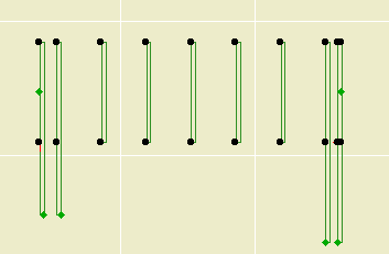
Plan Lines: The symbol is a rectangle, with Start, End, Right, and Left lines. Any of these can be turned off, to make the beam meet a wall more cleanly in plan, for example. If the Roll Angle is non-zero, you will also have the option of showing the Roll Corner Line in RCP. This line won't show in the floor plan.
3D Pen: If this pen is non-zero, it will be used in 3D instead of the object's plan pen.
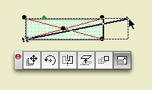
Start and End Miters: Turn these on and you can miter either end of the beam to meet other elements. The angles are graphically editable like any other mitered thing.
We have a special layer for elements we wish to see in plan and RCP, A Ceiling All. Use that layer for this beam.
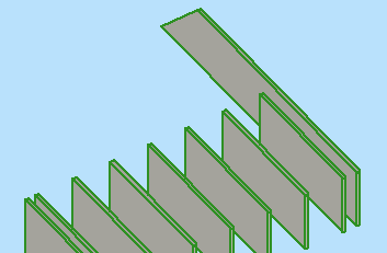
This object is better than a beam element if you're just talking about the RCP. But there are plenty of ways it's not as good. One big disappointment is that you can't cross a pair of them and have them clean up in 2D and 3D. Another, beams can use custom profiles. A weird profile object has to be coded.
So, this object isn't a replacement for all ceiling beams. If it's a cased beam, you'll want to use beam element with a custom profile. If the beams cross, you need beam elements to make them clean up.
And if you're using real beams, you need to trace in the RCP. But, tip: If you have crown inside coffers, you might be able to skip out on the tracing and just let the crown objects (on the F Trim Crown layer) imply the beam shapes.
Another potential frustration is the case of a structural, visible timber beam. Normal structure beams are created with the Wood Beam object, which gracefully labels itself in the framing plans. The layer for these new ceiling beams can't do this, because I don't have a practical way to show the beam in all three plans, but the text in only the framing plan. A promising solution would be to create a label to refer to the beam, which could then show only in structure. Alas, here Archicad has stymied us again, because you can't show a label when the labeled element is hidden. And we can't show the beam itself because it's dashed. And I'm not putting the structure plans in ceiling mode, because I have no idea what the side effects of that would be.
For this case, model the beam using the RCP Beam object, and place another (Wood Beam) object on the +S Struct Note layer, with the Model parameter off.
With Drawing Title 10a you can:
• Set the Orientation of the title. You can have the title rotate to align with the Drawing (default), the Layout, or a Custom Angle. Use the Layout option to keep the title horizontal when you rotate a drawing. This is optional, and it's not always right. For example, if you rotate a wall section to fit on the sheet, the title should rotate too. I can't think of a purpose for Custom Angle, but it wasn't hard to put in there. If you do ever use it, the angle is graphically editable.
• Choose a manual scale from a list. Leave the field empty to use the drawing's true scale. This is usually correct. To show no scale text, choose 'blank' from the list. You need to set a manual scale for a scanned detail PDF; now you can choose it from a list.
Location: 06 Wood & Plastic / 2D Wood
A 2D symbol for plates, blocking, or other non-finish wood. This one replaces Lumber Continuous JAM81 and Lumber Blocking JAM8.
If you Use Standard Sizes, you can select the Board Size from the list. Better, you can stretch the symbol graphically, and it will snap to the standard sizes.
With Use Standard Sizes off, you can use any dimensions and stretch the symbol whichever way.
The Cross can be an X for continuous lumber or a slash for blocking.
There are separate pens for the Outline and the Cross.
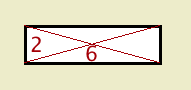
The Fill switch turns the symbol opaque white.
Location: 13 Special Construction
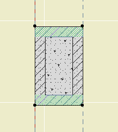
Two objects (primarily) for cutting coved recesses into ceilings, using solid element operations. One's a circle, one's a rectangle. Guess which is which. The parameters of each are similar.
The fillet radius must be less than or equal to the height. The resolution of the fillet is controlled by the Fillet Facets parameter. For the disc, the Resol parameter controls the resolution of the circle.
You can turn the objects upside-down with Flip Z. I can't imagine many cases for doing so, but you never know.
In practice, your ceiling slab will be the target, and the object will be the operator.
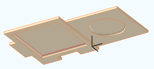
The 11 version of these objects adds the ceiling switch-awareness that we've used previously in Soffit Cutter JM11 and Ceiling Line JM11.
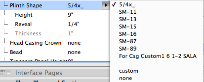
I added all the plinth shapes I could find to the interior door casings. Not all plinths will fit all jamb casings; you need to know what you're doing.
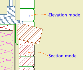
2D symbol for brick walls in large scale sections and details. It will alternate bricks and joints. The height of a brick is controlled by the Brick Triplet Height, which is the height of three bricks. You can directly set the Joint Width and Reveal.
In Section Mode, the width is set by the Brick Width parameter. In Elevation Mode, the width is set by the length parameter of the object. (I'm sorry if this seems a bit weird. The thinking is that in section you will always show a whole brick width, while in elevation you will often shorten the width to fit a window casing, e.g.)
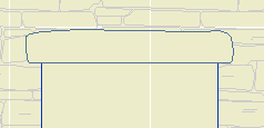
The Mask switch fills the joints with a white fill in Section mode, so the object can cover a vertical wall line beyond. If the distant line is heavy, use the Nudge parameter to make sure the fill covers it. In elevation mode, Mask makes the entire object opaque, including the joints.
The Brick Fill and Mortar Fill should be obvious. The pens are set by the symbol, cut, and cut fill pens of the object's settings.
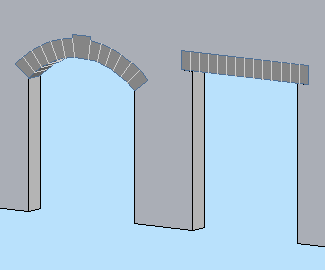
Make it Flat or not. If it's arched, you can set either the Spring Height or the Arch Height, and the other dimension will change to maintain the overall height.
If Flat is on, the arch/lintel can be Segmented (separate arch stones) or Solid (a one-piece lintel). With Flat off, the curved arch must be segmented and the Style parameter is hidden.
A Flat arch/lintel has options for the Bearing dimension and Angle at both ends. Example of angle usgae: A brick jack arch.
A segmented arch, Flat or not, will be made of stones measuring, at most, the Stone Max Width. You can have a Keystone, which can have its own Width. To omit the keystone, set the Keystone Height to 0.
The big new feature in this version is the Squiggly Stone option. This will give a (little) more natural shape to the lintel or arch stones. The squiggly parameters and behavior are different depending on whether the arch/lintel is 'Segmented' or 'Solid'.
In the current version, a segmented arch will only be drawn squiggly at scales less than 1/4" (1/2" scale and larger). This is to conserve resources in 3D/section/elevation, because the squiggly arch uses a lot more polygons. If you want to override the scale control, turn on the Force Nicer Arch parameter. I'm thinking about a way to do low-scale squiggly joint lines, but it's not ready at this time.
Note: A solid squiggly lintel is always squiggly, regardless of scale.
The Joint Pen is used to draw the joint lines on a non-squiggly or low-scale arch. This pen should be 150, the usual surface hatch pen. In addition, squiggly arch stones are modeled using this pen, so they don't stand out so much.
Materials: The visible arch/lintel will use the Arch Material. For a Squiggly, Segmented arch, the visible, squiggly stones are actually thin plates applied to the front of the wall. (You can't tell.) Behind that, within the wall, is a regular lintel, built with none of its edges visible. This is so the arch appears consistently in section. This invisible piece takes the material of the edge of the wall. If you look at the shaded view and see a funny color within the arch, check the wall's edge material. (For stone walls, the edge material should be stone so the masonry reveals look right.)
The overhead lines (Cased Op Lines) can be switched off individually.
Here are some 'recipes' for typical applications:
Precast lintel: Flat on, Solid, Squiggly off, lintel bearing>0.
Stone lintel: Flat on, Solid, Squiggly on, lintel bearing>0.
Flat Stone arch: Flat on, Segmented, Squiggly on.
Stone arch: Flat off, Segmented, Squiggly on.
Brick jack arch: Flat on, Segmented, Squiggly off, lintel angle>0.
Location: Like all markers, the location doesn't matter. Markers are selected directly in the settings dialog or info box.
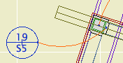
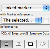
Place them using the first, single-click geometry method; you don't need to draw a box.
Location: 08b Windows
An array of screen window panels.
Horizontal Panels: Set it to zero if you want to automatically calculate the number of panels based on the Max Panel Width, or put in a number.
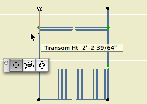
Both the rail transom heights can be edited in 3D and in section using the green nodes.
All the other parameters are identical to those of the single screen window. If the balusters are on, they will only be built in the lowest panels.
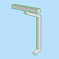
I added Rectangular options for the gutter and the downspout.
« Newer | All Entries | 1 | 2 | 3 | 4 | 5 | 6 | 7 | 8 | 9 | 10 | 11 | 12 | 13 | 14 | 15 | 16 | Older »