
This started, as so many things do, with making a symbol fill for a tile pattern. A challenge of symbol fills is they need to tile (left and right meet, top and bottom meet, invisibly).
You can make new grid, running bond, and herringbone fill patterns by duplicating the extant ones and changing the dims. Anything more complex, you need to draw and work out the tiling.
That's just the fill pattern, which is vectorial, meaning you can use it in plan and surface fills in elevation. But you are on your own in 3D (OpenGL, BIMx). If you are delivering BIMx, you need to keep your textures in sync with your fills. Here is a simple way to do that.
Location: 01 General / 1 Graphic Symbols

The shapes are square, rectangle, triangle, circle, ellipse, oval, diamond, hexagon, pointed box, and roundrect. The roundrect has authentic iOS proportions.
The rectangle, oval, hexagon, and roundrect will elongate to accommodate the text, if the Stretch for Text parameter is on. The square will turn into a rectangle.
The Height parameter refers to the vertical dimension. The Length Factor parameter is multiplied by the height to get the length of the rectangle, ellipse, oval, and roundrect shapes. If Stretch for Text is on, the length is overridden by the text length.
The text, by default, is the global ID of the object. You can also choose to enter a custom text.
The size of the text can be set by points, millimeters, or as a fraction of the shape height. All these parameters are hooked together, so when you switch among them the actual height stays the same.
There is a value list for the font, and you can enter any font name. The text can be shown bold, italic, underlined, or any combination.
The Mask parameter will make the shape opaque white, using the 'Solid' Fill and White Pen parameters.
The Shape Label is simply a label version of the same thing. When placed as an associated label, the ID displayed is that of the labeled element. Placed independently, you need custom text.
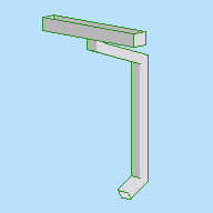
Location: 14 Conveying Systems /
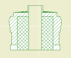
This is a hydraulic residential elevator based on a product line of a real company. Since I don't know how they feel about me 'using' their 'IP', I'm not saying who it is at this time. You could probably figure it out.
Because it's a real product line, there are limited size and configuration options. Under Cab Size there are three. Under Door Configuration there are various. Some of the door configurations offer the option to have the door hinge from the 'Track' side of the elevator or the 'Opposite' side. If this parameter doesn't apply, it is hidden.
You can choose the configuration visually under the 'Configurations' interface tab.
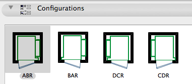
There is a read-only Configuration Code which is generated from the Door Configuration and the Hinge Side. This is from the product catalog.
I have provided a Standard Sizes parameter which locks the length and width to the catalog data. I wouldn't turn this off; I would rather know how big the real equipment is. The only case where I would turn it off is where I was using another manufacturer and the configurations were similar but the exact dimensions were different. Anyway, it's stretchable in principle, but the default is to be locked to the standard sizes. Turn this switch off and stretch to any impossible shape you want, YMMV.
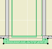
Place the object on the bottom story of the elevator's true extent. Show the object on All Stories. Set the object's Stories Served parameter to reflect the number of actual stories the elevator will serve. The 2D symbol will not be shown above or below this range. (Though (Archicad fail) the object will still be selectable via Select All on stories where it is not visible.) The wall track which supports the cab will automatically extend through all but the top story being served by the elevator. The top story is covered by the value in the Top Rail Height parameter. This value should be roughly the top story's ceiling height. (I found in most cases that the track was too tall if it ran the whole top story.)
The Raise Cab parameter determines how many stories the cab will be raised in 3D from the home (bottom) story. This would only matter if you cut a section through the elevator shaft, and frankly it wouldn't matter much even then.
Pit.
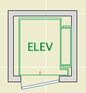
In plan, it looks like an elevator. The length and width dimensions are based on the finished dimensions of the shaft. The text bit should center in the car and it can be customized if "ELEV" doesn't suit you. There is a red (pen 10) line at the center of the door(s), and nodes at the edges of the doors. The door is not part of the object; you need to place a door in a wall normally. There are also hotspots at the center of the track and at the centerlines of the required structure for the track.
The associated pump equipment is a separate object, Elevator Equipment JM16. I also have a call box symbol for the electrical plan, Elevator Call Switch JM16.
Download (AC16)
Location: 01 General / 1 Graphic Symbols
This is your basic CL symbol, since most fonts don't have it. You can change the font and size, and apply bold formatting. It's is an update to CenterLine Sym JM9, which it replaces. It should be on BIMcomponents soon, or you can download it here. I've added two features based on community feedback.
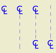
First is the option to show a line in addition to the symbol. If the line is shown, you have the option of repeating the CL symbol at the other end.
Update: If the line is shown and the symbol at the end is on, the symbol at the start can be turned off. In this way you can have the line pointing up from the symbol.
Second, I saw Jakub Chruscinski's version of my old symbol on BIMcomponents, which includes a complete font list in the text options. I'm offering the complete list as an option since it seems like something people like, but it defaults to off. I prefer to restrict the list to our standard fonts.
The default font is Arial in the version I am sharing, but the sublime font in the preview is Gill Sans, which is what we use in practice.
Wonkish: The symbol code consists of two text blocks whose alignment is set using X and Y coordinate offsets with absurd precision (0.0001"). Not all fonts will look right automatically. To get an arbitrary font to look good, you might need to open the 2D script and modify the offsets.
Placement tip: Set the object to insert by the top or bottom hotspot, and use the Rotated geometry method of the object tool.
Download (AC16)
Download (AC11)
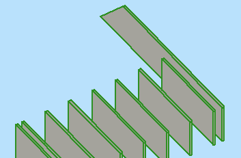
Two tweaks to the Railing JM9 object.
Another one for the well-under-4KB* series...
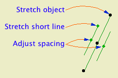
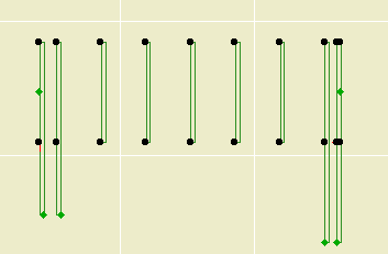
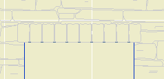
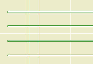
The length of the object is the length of the long line. The length of the short line is set by the Short Line Factor parameter. You can adjust this factor graphically. The spacing of the lines is controlled by the Spacing parameter. Also graphi-justable.
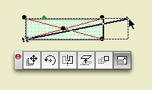
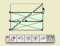
This is a good one to place with the rotate and stretch geometry method (fourth button). With this method I had an intermittent glitchy behavior where the object would appear offset from my clicks, but I couldn't reproduce it.
I wanted to add this symbol to our doors and windows directly, but I don't think it's possible to force the lines to tilt rightward in every case, once you factor in the orientation of the door and the viewpoint and all that.
Download (AC11)
* Until you add the preview image.
Converting 2D elements for use in 3D.
Any 3D element(s) can be saved as an object with the Save Project As... menu command. (In Archicad 11, Save 3D Model As...) This technique is known as 'slabifying' since such models are often built from slabs. Objects saved in this way are dumb (not parametric), but it's still a useful trick.
2D elements can't be saved this way, because they never appear in the 3D window, where 3D object saving takes place. Despite the fact that GDL contains commands for 'flat' shapes in 3D, including LIN_ (a line) and PLANE (not a joinery implement). But there is a workaround for 'slabifying lines'. When you open a 2D DWG as an object, 2D lines are created as LIN_ statements in the 3D script. When you place the object in the model, you get the 2D geometry in 3D.
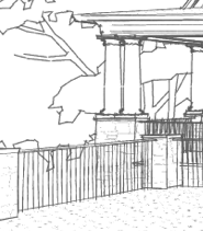
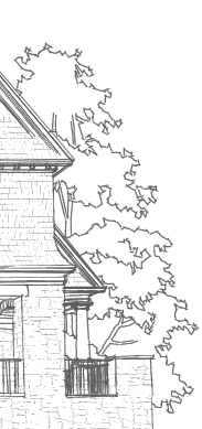
It's that simple at it's simplest, but real world applications need some tweaking. In this example, I'm converting an Archicad library 2D tree elevation symbol so I can use it in a sketch render image. Other applications might be a complex ornament in a hidden line elevation, or a busy glazing design placed in front of a conventional window.

Materials for rind, flesh, and stem. Expression can be happy or sad. I've had this for nine years; I finally took the inline material definitions out.
Download (AC11)
I added an option for an elliptical curve. Original and download link here.
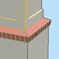
An extrusion in the shape of a sloped brick rowlock course. Set the Angle and Brick Width of the rowlock, and the Thickness and Air Space of the veneer it rests upon.
Yes, you could use a custom profile for such a thing. But if you wanted to change the slope or the brick dimensions you would need to draw a new profile. And profiles can't change in response to the scale.
Profiles are simpler, at least until you have too many of them. Objects are smarter. Now if we could script a profile...
Bracket Strut JM9: More top and bottom end shapes: Cove, chamfer, and fillet.
Chamfer Cutter JM9: Chamfer multiple corners at once.
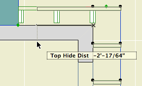
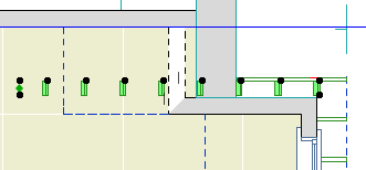
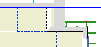
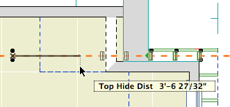
Rafters Decorative JM9a: Like the eave ladder, you might want to see exposed rafters in the reflected ceiling plan. But you need to be able to hide the portion of the rafter object that is hidden by the main roof. Adjust the Top Hide Distance to meet the main roof cut:
Location: 06 Wood & Plastic
A sloped series of boards to support a flying rafter.
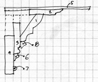
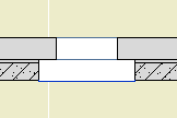
This thing is hard to show in place; here's a section through the eave of a dormer, showing the dormer wall in elevation:
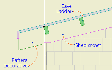
The Roof Slope can be selected from a familiar list of n/12 slopes, or you can use a custom angle.
You can choose the board Stock from the list, or use a custom Height and Width. Spacing is measured along the slope.
Location: 06 Wood & Plastic / Brackets
An Arts & Crafts type bracket. Parameters: Length, height, width, top/bottom thickness, top/bottom end treatment, strut thickness, width, and top/bottom inset.
The end treatments are Square, Ogee, and Pyramid. May 2008 update: Cove, Fillet, Chamfer.
You can turn on "Both Ends Same" to use the same values for the top and bottom. In this case, the bottom-related parameters are hidden.
Most of the parameters are editable in 3D.
Though I kept the '9' in the name, this is for Archicad 11.
Originally posted 2005-03-29
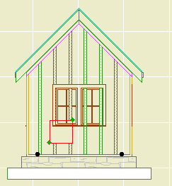
Location: 06 Wood & Plastic / Trim & Moulding
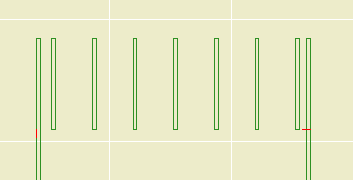
A series of battens for board and batten siding. There are parameters for Width, Thickness, and Spacing. For a single batten, set the spacing to zero.
In order that you can do a whole wall with one Battens object, you can have up to eight Holes in the batten arrangement. Turn on as many holes as you need and fit them to the windows and doors. You can do this in section or elevation using the editing hotspots.
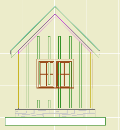
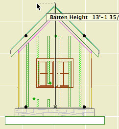
Use solid ops to trim the battens to the roofs.
Download (AC11)
Location: 01 General / Drawing Tools
System requirements:
Accessories add-on in Add-ons folder
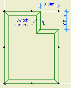
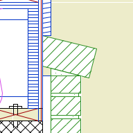
An accessory as a special object that can be associated with another element. When you edit the element, the accessories edit themselves to keep up. This kind of automatic geometry is rare in Archicad, and welcome. Yet the accessories live in the limbo of semi-features known as the Goodies, where they are not installed by default, and you have to download them, and they're soaked with disclaimers. Anyway.
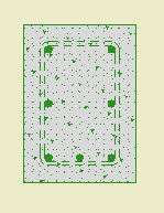
This accessory traces the slab perimeter with a line that can switch its parameters in response to the ceiling switch. So, while that switch only works on objects, by using an accessory (object) we can trick it into working on slabs too.
The main application is a continuous soffit around a room. You should build such a thing with a slab with one big hole in it. With the accessory, you can show the hole perimeter correctly in plan and RCP. The slab would go on the A Ceiling3 layer, and the accessory object would go on A Ceiling All.
The parameters are the same as ceiling line. The only additional option is Holes Only. This traces only the holes within the slab, not the main polygon.
To place the accessory on a slab:
Select the slab.
On the Design menu, Design Extras -> Accessories -> Slab Accessories...
In the object dialog that pops up, choose the Ceiling Line Aceessory.
When you edit the slab, the lines will update automatically.
Location: Doesn't matter.
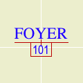
Unlike the room name object, the name and number are not parameters. They are native settings of the zone, and are available at the top of the settings dialog or info box. Further, the font and text size for the room name are settings of the zone.
The rest of the parameters are in the 'Zone Stamp' area of the zone settings dialog.
Location: 08b Windows / Vents (A window)
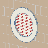
Louver parameters: Thickness, Spacing, Angle. The Louver Pen should be thin.
Exterior casing: Typical moulding options, or custom width and thickness.
Interior casing: Same deal.
Either casing can be turned off. The same Casing Reveal is used for both.
Masonry Cut Depth: Same as a window or door. Sill is drawn with the Masonry Sill Pen, though in most cases you would not see this vent in plan.
Location: 08b Windows / Vents (A window)
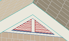
The width and height of the vent are both tied to the slope. If you change either one, the other is adjusted to maintain the slope.
Frame thickness refers to the box around the louvers.
Mullion thickness: The center mullion, where 0 means no mullion.
Louver parameters: Thickness, Spacing, Angle. The Louver Pen should be thin.
Exterior casing: There are separate widths for the sides and bottom. All parts are the same thickness.
Interior casing: Same options.
Either casing can be turned off. The same Casing Reveal is used for both.
Masonry Cut Depth: Same as a window or door. Sill is drawn with the Masonry Sill Pen, though in most cases you would not see this vent in plan.
Location: 11 Equipment
A rather vague but configuration-complete washer and/or dryer.
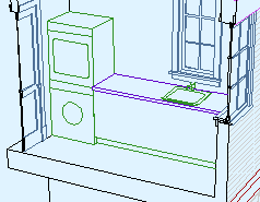
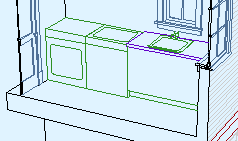
Front load washer: If on, there's a porthole in the front, otherwise, a lid on top. Automatically on if stacked. You can set the glass material.
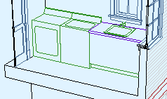
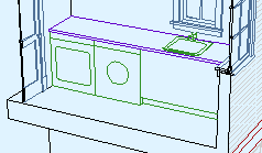
The fill pen should usually be 91, unless you want the plan symbol transparent for some reason.
Text size and font are obvious. The object labels itself 'W/D' for the stacked version, or 'W' and 'D' for the side-by-side.
In the rare case where you want just one of the units, you can set Units to 'Washer' or 'Dryer' rather than the more common 'Both'.
In Archicad terminology, a marker is a special object that has a subordinate relationship to another element, representing the element and/or saying something about it. Viewpoint markers represent viewpoints in project windows. Each viewpoint type has its own marker objects. There are default markers for each one in the Archicad library, but we (as usual) use customized stuff. Each marker is dedicated to a viewpoint, but all the markers have a lot of parameters in common. Here I will lay out those similarities, as well as the special features of each marker, while making sure we're clear on the correct marker for each viewpoint type.
Location: 04 Masonry / Chimney & Fireplace
The chimney proper is built from walls and slabs. At the top things tend to get weird, with a lot of zigging back and forth. This object should help with that, as well taking care of ending the flues.
Executive summary: Build up a stack of up to eight stages of masonry. The stages can be offset to each other, and can slant as needed. The flues are cut through the stack. Flues can be arranged automatically or moved around.
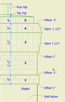
You can have up to eight, and you can have none. (Let me know if you need more.) Each stage is turned on by setting its thickness to greater than zero. Stages must be built in order. If a stage has zero thickness, those following it are not available.
Each stage has parameters for Thickness, Offset to Last, Slant, Material, and Section Fill. Offset is the difference in size from the top of the previous stage. (The first stage is offset to the objects length and width, which will match that of the chimney elements below.) Slant allows the stage to get narrower or wider toward the top; positive values increase size, negatives decrease. A slant of zero is vertical.
The first stage should always be offset; if it's flush with the chimney, you should eliminate it and make the chimney (walls or slabs) taller.
Quantity between zero and four. I think the zero case would be quite rare, but there it is.
All the flues will use the same Material and Section Fill parameters.
Flue dimensions can Match, or they can be set independently.
Flue Arrangements: Both Auto arrangements line up the flues down the middle of the chimney. Auto Max spreads the flues as far as possible between the ends of the object, staying within the Minimum Chimney Thickness. Auto Min puts the flues as close together as possible in the middle, with the Minimum Flue Spacing between them. Customize allows you to move the flues around in plan using the editing hotspots.
Note that the object doesn't check if the flues fit; it's up to you to make sure the whole thing is big enough.
Flue Height Above Chimney is the distance the flues stick out the top.
The Flue Thickness in Section option shows the flue thickness all the way through the chimney. Otherwise, the flues are simply sitting on top of voids cut directly through the chimney parts. You will usually have this parameter off in order to line up better with the flues in the chimney below. As discussed here, it is nigh-impossible for the flue object to show its thickness. If it ever becomes possible, the chimney top will be ready.
Section only. Obviously. There's a big blob of something, probably CMU, in the center of the chimney, cutting through all the stages except the top one. The Veneer Thickness controls how much of the stages remains on the outside.
Sloped parging on top of the last stage. The top slopes up to the Top Height, forming a plateau which traces the flue outlines. The top gets its own material and section fill. The top can be on even if all the stages are off.
Related:
Chimney/Fireplace 1: Fireplace in Plan
Chimney/Fireplace 2: Chimney in Plan and 3D
Chimney/Fireplace 3: Flues
Chimney/Fireplace 4: Hearth Structure
Original here.
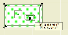
I tweaked the Shape Tag object so you could have a masking fill within the polygon.
The intent is to show a solid white fill. To ensure wide compatibility, I've provided parameters for the fill and the white pen. Non-locals may want/need to change the defaults to their preferred solid fill and white pen.
Location: 06 Wood & Plastic
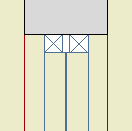
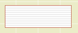
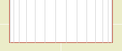
A beam, or any other ceiling element, should be shown dashed in the architectural plan, because it's overhead. That same beam needs to be shown solid in the reflected ceiling plan, because then you're upside down looking straight at it. Using a conventional beam element, you would draw it with a dashed line in plan. But you can't show the same element in the RCP, because you can't make the beam draw itself solid. So you trace the beams with lines.
In Archicad 11, we have a model view option which allows objects, but only objects, to be drawn differently in floor plans and ceiling plans. This object is a simple wood beam that responds to this switch, so you don't have to trace it in RCP. There are limitations to using this instead of a beam element, see below. But for a simple beam such as a timber, you definitely should consider this object.
Size: Choose a dimensional lumber size, or choose 'Custom' and set the Depth and Thickness manually.
Slope: The usual roof slopes, or a custom angle. If the beam is sloped, parameters are available to control the Top and Bottom edge angles.
Roll Angle: Turns the beam around the long axis. If the beam is sloped this parameter is not used.
Plan Cover Fill: Just what it says. Turn it on and set the attributes, or don't.
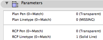
RCP Attributes: The Pen and Linetype that will be used when the ceiling switch is on. When the switch is off, the object's 2D symbol will be drawn with the object's settings. In practice, the object should be set to use a dashed line, while the RCP linetype is solid. The pen doesn't really need to be different in most cases, but the option is there.
Pay no attention to where it says 'Transparent' when the pen is zero, and 'MISSING' when the linetype is zero. Those indicators are automatic and I can't get rid of them. In our case, zero means 'Match the object's settings'.
RCP Cover Fill: Just what it says; this fill will be used when the ceiling switch is on. This can give you some ability to show beams stacking in the ceiling, such as joists running over a timber beam.
Plan Lines: The symbol is a rectangle, with Start, End, Right, and Left lines. Any of these can be turned off, to make the beam meet a wall more cleanly in plan, for example. If the Roll Angle is non-zero, you will also have the option of showing the Roll Corner Line in RCP. This line won't show in the floor plan.
3D Pen: If this pen is non-zero, it will be used in 3D instead of the object's plan pen.
Start and End Miters: Turn these on and you can miter either end of the beam to meet other elements. The angles are graphically editable like any other mitered thing.
We have a special layer for elements we wish to see in plan and RCP, A Ceiling All. Use that layer for this beam.
This object is better than a beam element if you're just talking about the RCP. But there are plenty of ways it's not as good. One big disappointment is that you can't cross a pair of them and have them clean up in 2D and 3D. Another, beams can use custom profiles. A weird profile object has to be coded.
So, this object isn't a replacement for all ceiling beams. If it's a cased beam, you'll want to use beam element with a custom profile. If the beams cross, you need beam elements to make them clean up.
And if you're using real beams, you need to trace in the RCP. But, tip: If you have crown inside coffers, you might be able to skip out on the tracing and just let the crown objects (on the F Trim Crown layer) imply the beam shapes.
Another potential frustration is the case of a structural, visible timber beam. Normal structure beams are created with the Wood Beam object, which gracefully labels itself in the framing plans. The layer for these new ceiling beams can't do this, because I don't have a practical way to show the beam in all three plans, but the text in only the framing plan. A promising solution would be to create a label to refer to the beam, which could then show only in structure. Alas, here Archicad has stymied us again, because you can't show a label when the labeled element is hidden. And we can't show the beam itself because it's dashed. And I'm not putting the structure plans in ceiling mode, because I have no idea what the side effects of that would be.
For this case, model the beam using the RCP Beam object, and place another (Wood Beam) object on the +S Struct Note layer, with the Model parameter off.
With Drawing Title 10a you can:
• Set the Orientation of the title. You can have the title rotate to align with the Drawing (default), the Layout, or a Custom Angle. Use the Layout option to keep the title horizontal when you rotate a drawing. This is optional, and it's not always right. For example, if you rotate a wall section to fit on the sheet, the title should rotate too. I can't think of a purpose for Custom Angle, but it wasn't hard to put in there. If you do ever use it, the angle is graphically editable.
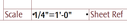
• Choose a manual scale from a list. Leave the field empty to use the drawing's true scale. This is usually correct. To show no scale text, choose 'blank' from the list. You need to set a manual scale for a scanned detail PDF; now you can choose it from a list.
Location: 06 Wood & Plastic / 2D Wood
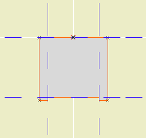
A 2D symbol for plates, blocking, or other non-finish wood. This one replaces Lumber Continuous JAM81 and Lumber Blocking JAM8.
If you Use Standard Sizes, you can select the Board Size from the list. Better, you can stretch the symbol graphically, and it will snap to the standard sizes.
With Use Standard Sizes off, you can use any dimensions and stretch the symbol whichever way.
The Cross can be an X for continuous lumber or a slash for blocking.
There are separate pens for the Outline and the Cross.
The Fill switch turns the symbol opaque white.
Location: 13 Special Construction
Two objects (primarily) for cutting coved recesses into ceilings, using solid element operations. One's a circle, one's a rectangle. Guess which is which. The parameters of each are similar.
The fillet radius must be less than or equal to the height. The resolution of the fillet is controlled by the Fillet Facets parameter. For the disc, the Resol parameter controls the resolution of the circle.
You can turn the objects upside-down with Flip Z. I can't imagine many cases for doing so, but you never know.
In practice, your ceiling slab will be the target, and the object will be the operator.
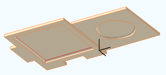
The 11 version of these objects adds the ceiling switch-awareness that we've used previously in Soffit Cutter JM11 and Ceiling Line JM11.
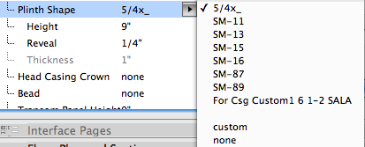
I added all the plinth shapes I could find to the interior door casings. Not all plinths will fit all jamb casings; you need to know what you're doing.
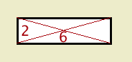
2D symbol for brick walls in large scale sections and details. It will alternate bricks and joints. The height of a brick is controlled by the Brick Triplet Height, which is the height of three bricks. You can directly set the Joint Width and Reveal.
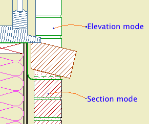
In Section Mode, the width is set by the Brick Width parameter. In Elevation Mode, the width is set by the length parameter of the object. (I'm sorry if this seems a bit weird. The thinking is that in section you will always show a whole brick width, while in elevation you will often shorten the width to fit a window casing, e.g.)
The Mask switch fills the joints with a white fill in Section mode, so the object can cover a vertical wall line beyond. If the distant line is heavy, use the Nudge parameter to make sure the fill covers it. In elevation mode, Mask makes the entire object opaque, including the joints.
The Brick Fill and Mortar Fill should be obvious. The pens are set by the symbol, cut, and cut fill pens of the object's settings.
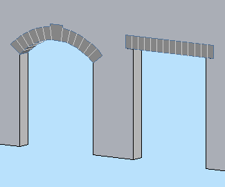
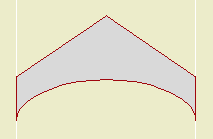
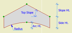
Make it Flat or not. If it's arched, you can set either the Spring Height or the Arch Height, and the other dimension will change to maintain the overall height.
If Flat is on, the arch/lintel can be Segmented (separate arch stones) or Solid (a one-piece lintel). With Flat off, the curved arch must be segmented and the Style parameter is hidden.
A Flat arch/lintel has options for the Bearing dimension and Angle at both ends. Example of angle usgae: A brick jack arch.
A segmented arch, Flat or not, will be made of stones measuring, at most, the Stone Max Width. You can have a Keystone, which can have its own Width. To omit the keystone, set the Keystone Height to 0.
The big new feature in this version is the Squiggly Stone option. This will give a (little) more natural shape to the lintel or arch stones. The squiggly parameters and behavior are different depending on whether the arch/lintel is 'Segmented' or 'Solid'.
In the current version, a segmented arch will only be drawn squiggly at scales less than 1/4" (1/2" scale and larger). This is to conserve resources in 3D/section/elevation, because the squiggly arch uses a lot more polygons. If you want to override the scale control, turn on the Force Nicer Arch parameter. I'm thinking about a way to do low-scale squiggly joint lines, but it's not ready at this time.
Note: A solid squiggly lintel is always squiggly, regardless of scale.
The Joint Pen is used to draw the joint lines on a non-squiggly or low-scale arch. This pen should be 150, the usual surface hatch pen. In addition, squiggly arch stones are modeled using this pen, so they don't stand out so much.
Materials: The visible arch/lintel will use the Arch Material. For a Squiggly, Segmented arch, the visible, squiggly stones are actually thin plates applied to the front of the wall. (You can't tell.) Behind that, within the wall, is a regular lintel, built with none of its edges visible. This is so the arch appears consistently in section. This invisible piece takes the material of the edge of the wall. If you look at the shaded view and see a funny color within the arch, check the wall's edge material. (For stone walls, the edge material should be stone so the masonry reveals look right.)
Jambs of two arches
The overhead lines (Cased Op Lines) can be switched off individually.
Here are some 'recipes' for typical applications:
Precast lintel: Flat on, Solid, Squiggly off, lintel bearing>0.
Stone lintel: Flat on, Solid, Squiggly on, lintel bearing>0.
Flat Stone arch: Flat on, Segmented, Squiggly on.
Stone arch: Flat off, Segmented, Squiggly on.
Brick jack arch: Flat on, Segmented, Squiggly off, lintel angle>0.
Location: Like all markers, the location doesn't matter. Markers are selected directly in the settings dialog or info box.
Place them using the first, single-click geometry method; you don't need to draw a box.
Location: 08b Windows
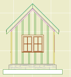
An array of screen window panels.
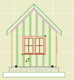
Horizontal Panels: Set it to zero if you want to automatically calculate the number of panels based on the Max Panel Width, or put in a number.
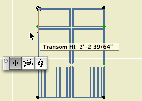
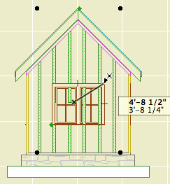
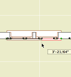
Both the rail transom heights can be edited in 3D and in section using the green nodes.
All the other parameters are identical to those of the single screen window. If the balusters are on, they will only be built in the lowest panels.
I added Rectangular options for the gutter and the downspout.
Location: 08b Windows
A simple screen panel for a screened porch. Not a screen for a window unit.
Frame Width and Thickness: Dimensions of the border trim. There are two frames, one inside and one outside, with the screen in the middle.
Balusters are optional; set the Width and Spacing. The balusters are built within the inside frame. They can have their own pen, which should be thin.
Frame and Screen Material: Obvious.
3D Cut Pen: A window hole is usually outlined with the wall's 3D pen. This parameter lets you use a different pen for the hole.
Location: 06 Wood & Plastic / Shutters
Note: Though the name says 9, it needs 10.
Very basic window shutter(s), perfect for existing conditions.
Single or Pair: If it's a pair, the shutters will be spaced using the object's length setting. This way you can stretch the opening to fit a window.
If it's a pair, you can Fit Pair To Opening, which sets the shutters' width to half of the opening dimension. If Fit is off, or if it's a single shutter, Shutter Width controls the width.
The basic dimensions of the shutter are Frame Thickness, Frame Width, and Panel Thickness.
Panel Type can be Flat, Raised, or Louvers. If it's Raised, you can set the Width of the border and Thickness of the raised part. For louvers, use a fine weight for the Louver Pen.
We don't have infinite panel arrangement options; it's a basic shutter. You can have one or two panels. You can have Equal Panel Heights, or a Square Panel at the top or bottom, or you can set the Bottom Panel Height manually.
Location: 13 Special Construction
A big dull block for subtracting a rectangular hole into a ceiling slab. Why not use a slab for an operator? Why not just draw a conventional hole in the slab? Because while the 3D block is dull, the plan symbol is rather clever, responding intelligently to the new ceiling switch in Model View Options.
To review what the ceiling switch is all about, check the Ceiling Line JM11 post. Like that line object, the soffit cutter has separate attribute settings for plan and RCP. Either set of attributes can match the objects settings, while the other can differ. I like to treat the plan as primary and the RCP as the variation, so I have the object's linetype set to 'Dense Dashed'. In the parameter list, the Plan Linetype is 0 (matches the object settings), and the RCP Linetype is Solid Line. You can also change the pen, but I don't see the need.
The cutting takes place with solid element operations, with the main ceiling as target and this object as operator.
Such an object has peculiar display requirements so the layer is very important. It shows in plan, RCP, and working model/section/elevation (so you can work with it), but is hidden in output sections (where you want to see the effect of the operation but not the operator itself). So in the templates we have a new layer, X Ceiling Cut. Like most cutting layers, it's wireframe. You would need to create this layer in running projects and show/hide/wireframe it as described.
Of course, sadly, for a non-rectangular hole you still need to use a slab, and you still need to trace.
Original here.
You can have a Second Crown above the first one. The Nudge parameter controls the overlap of the two crowns in section. And, a Cap, which is just a block like the base. (Turn all the mouldings off and you have a simple post.) And, a Bead moulding between the panels and the top crown.
Location: 03 Concrete
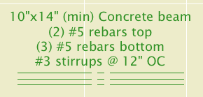
A 3D concrete beam with rebars, and/or a 2D symbol of a concrete beam section.
Placed in...
Model means a 3D beam that will show up in plan and section. Note that the actual placement will very likely take place in the plan window.
2D Detail means a 2D symbol of the section through the beam, suitable for placement in a detail or wall section window. This mode has no 3D part.
Depth is the Z dimension.
Top Width allows you to make the top wider for slab-thickening applications. Zero means keep it rectangular.
Rebar Size: Choose a number.
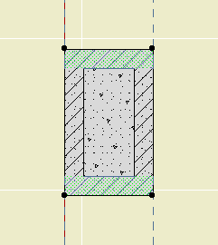
Section through Model beam
Note that the bars are not modeled at scales smaller than 3/4". They will be visible in wall sections, but not building sections.
2D Detail mode with stirrups
Concrete controls the display of the 3D beam itself in Model mode, and the fill pattern in 2D Detail mode. This effectively gives the option of 'bars only' for cases where the concrete is already represented by another element, such as a 'real' beam.
Beam Outline: 2D Detail mode only. Controls the display of the rectangle, independent of the fill.
In Plan
The Label is for calling out the beam in framing plans. By default the label describes the width, depth, rebars, and stirrups. Label Bars Only turns off the dimension part. (min) adds that text after the beam's height dimension. Stirrup Spacing only applies to the label; remember the stirrups are not modeled.
I think the label is pretty intelligent about describing the beam's composition in most cases, but if you push past its limits you can turn on the Custom Label and write whatever you want on the three lines.
ID Tag is the typical circle for referring to the beam's structural calculations.
Tips:
• For a simple opening in a concrete wall, use Model mode, turn the Concrete off, and set the label to Bars Only.
• Modeling the beam is usually preferable. The only thing the modeled beam can't do in section is show the stirrups. You can add a section symbol for the stirrups by using 2D Detail mode, Concrete off, Stirrups on, zero rebars.
Location: 13 Special Construction
For modeling a vaulted ceiling under a flat ceiling or a gable roof.
Heights are editable in 3D and section.
Turn on the Ellipse parameter for an elliptical curve. Other wise it's a simple arc.
With the Model View Options in 'ceiling mode', the object can use the optional ceiling pen, linetype, and cover fill. (Use the layer F Trim Crown, which shows in RCP and section/elevation combinations.)
The Arc Lines option will draw lines with variable spacing to illustrate the curve:
You can use the arc lines as a 2D-only symbol by turning the Model parameter off.
Download (Requires Slope macro)
Electrigon is a free set of symbols for electrical fixtures with the ability to calculate electrical requirements for a project. The new version brings some more geometry options and improved calculations.
Yes, such functionality should ship with Archicad. We do what we can.
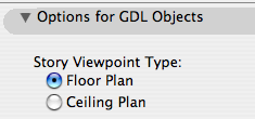
In Model View Options
Among the least heralded new features of Archicad 11, tucked into the bottom of the Model View Options dialog, is the modestly named 'Story Viewpoint Type'. Not heralded at all, in fact; there's no mention of it in the New Features Guide. I understand why they don't want to call it out too loudly. Its impact is rather narrow, and the Archicad library itself makes very limited use of the feature.
Right, what is it. It's the long-awaited (by me) environment switch to put the floor plan window in 'Ceiling Plan' mode. Wouldn't it be nice if things could draw themselves dashed in plan and solid in RCP or vice-versa. Less tracing, less maintenance, more unity. This is a pet issue of mine, so I'm happy to see it, even in its narrow, modest, unheralded current state. I'm calling it the 'ceiling switch' because no one knows what 'Story Viewpoint Type' means.
The switch gives the opportunity to have objects draw themselves one way in plan and another way in RCP. But: Only objects, which includes doors, windows, and lamps. It does not apply to regular modeling elements such as slabs and beams. Keep hope alive.
I've made several objects which take advantage this tech, and I plan to retrofit more as we go.
The first one is, a line! Haha! I know, if things are more unified you should draw... less! It's ironic. But there's more to come and this serves to illustrate the basic idea.
You could do the reverse: Let the RCP use the object settings and customize the plan parameters. Either way.
What's it for? Roof overhangs. You have to draw them anyway, because showing the roofs themselves is a mess. Use this object instead of a line, and get the overhangs in plan and RCP simultaneously. And: Miscellaneous ceiling lines such as those in an attic.
We need a new layer, which is A Ceiling All. This layer shows in plan, RCP, and all the model combinations.
To handle the ceiling switch itself, we need a new Model View Option combination, which is A4 RCP. In previous versions, the RCP used A4/S0/M/P; now that one's just S0/M/P. When migrating a project, you'll need to create this model view combination and assign it to the RCP views.
Location: 04 Masonry / Chimney & Fireplace
It's very hard to describe this object independent of the whole chimney process, but I'm going to try. Once this guy is written up we can look at how it, the firebox, and the flue work together.
This version is superior to the JM9 version in that the flue is better oriented with the firebox. In other words, it's less wrong.
The smoke chamber object makes a void. It is intended as an SEO operator. Like the flue, it's supposed to drill a hole through the chimney material.
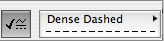
Parameters in plan
The object is wider than its Width by the value in the Firebox Wall Thk parameter.
So that's four parameters that the smoke chamber takes from the firebox.
Likewise, Flue Width and Flue Depth should correspond to whatever you're using for the flue.
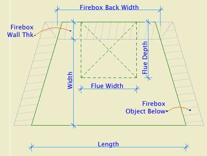
Parameters in section
Throat Height is the dimension of the plumb portion of the front of the object. Damper Height is the height of the sloped portion, which straightens out again at the flue depth.
Shelf Depth is measured down from the Throat Height. It carves out the place where you have to draw in the curved bit of mortar.
Throat Adjustment doesn't make sense until you see how the smoke chamber and firebox subtract from the chimney material. It's there to keep that vertical edge with the firebox wall, so there's no excess wall stuff hanging down.
Place the object on the layer A Flue. Use a non-printing pen (60 is good), and the material you want to see on the inside of the subtracted space (Brick Surface Color is good).
A Flue shows in plan, so the non-print pen hides the object in output. It also hides the weird lines on the surface of the object in section, which would be visible in the targeted chimney material. You can choose to show the smoke chamber's "flue X" by turning on Show Flue.
Location: 01 General / 1 Graphic Symbols
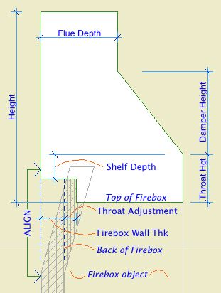
UPDATE 2019-11-12: Replaced the solid fill called by name with the global variable for the first solid fill in the fill list. (This might be 100%, 'Solid Fill', 'Foreground Fill', etc.) Now the mask fill won't fail if the 'Solid Fill' isn't available. This version is for Archicad 22.
UPDATE: Backsaved version for AC9.
Same features as the AC9 version, with a simplified interaction for getting the loop off center.
Location: 06 Wood & Plastic/Trim & Moulding
New version of the main moulding object.
Listen, you will have dozens or hundreds of Crown Tool elements in a project. The object is designed to be used all the time. I.e., it does a lot. Get familiar with what it can do. If it doesn't do something you need, speak up!
This version: There are additional 'shapes' and more parts available. New shapes:
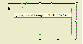
• "J"; like "U" with an independent length for the third segment.
• Rakes, including curved rakes.
• Arch.
New parts:
• Wall Backer 2. Placed behind the Wall Backer.
• Crown Cap. Placed below the crown.
• Soffit. Flat piece placed above the ceiling backer. You will often need this to help the rakes cut the roof edges.
I regret to inform you that I can't continue support the custom interface panel at this time, so we're stuck with the parameter list. Essentially, all this stuff is hard enough to simply get working, and the user interface development tech is painfully disrespectful to time constraints. I have to choose between features and interface and it isn't a hard choice. If this makes you unhappy reread the new features list above and cheer up!
Full documentation below the fold.
Location: 12 Furnishings / Casework
Another tweak to the blob. You can turn the Front Panel off. Why? So you can build the front of the cabinet out of a wall, and place the doors using 12 Furnishings / Casework / Cab Door Door JAM81. You would place that with the door tool, yes. (There's also Cab Door Object JAM81, the object tool implementation of the same thing.)
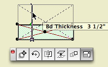
While I was in there I added a parameter for the box Stock Thickness. It defaults to 3/4". So the wall thickness should be 3/4" unless you change that parameter.
In plan, the front line is drawn at the front of the front, whether the object's panel is on or off. Tip: Use the front line as a guide to draw the wall.
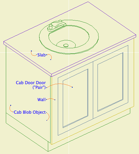
I know, I forgot the handles, sorry
Location: 06 Wood & Plastic/Trim & Moulding
The baseboard tool is for baseboards. That's pretty much it.
Feature Summary Baseboard profile, cap, shoe, and 'second' (lower) base; scale sensitive profiles and fills.
The baseboard tool is similar to the crown tool. The same shapes are available. (Pardon me if you find the term 'coffer' misplaced when considering base.) The miters and returns are the same. The scale sensitivity is the same, including the fills.
Here's the custom interface panel. Some of the options in the 'shape' area will change depending which shape is chosen.
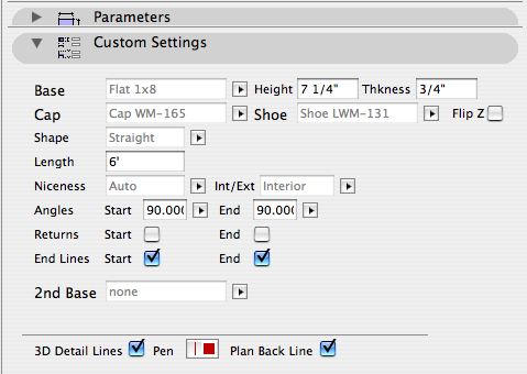
All of the parts are optional except the base itself.
At building section scales, the shoe and cap are not modeled. The base will be shown at the height of the top of the cap.
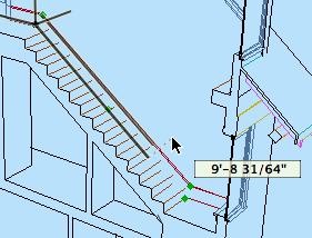
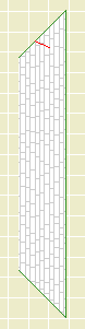
New in 10 version: Slope.
Tip: Copy and paste the angle from the Stair Body object. The high end is the start end and the slope is down. The start end is represented in plan by the red diagonal line.
If the base slopes and meets other base pieces, it's going to need to miter in the other direction. For this we have Start Vert Cut and End Vert Cut. Level pieces can also be cut this way, since they might have to meet a sloped one.
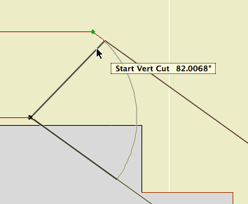
Tip: First over extend the angles so they cross, then you can detect the point where they meet as an intersection.
You will usually need more height on a stair base than the level bases it meets.
Baseboard elements should generally be placed on the layer F Trim Int Lo.
All of Swoop JAM9a still in effect.
Added:
-- Optional Cover fill and all related parameters. You can allow the slope of the object to Distort the fill. No, the distortion doesn't vary as the slope changes. You can move the fill's origin using a hotspot; you have to select the object to see it. The hotspot.
With the cover fill on you should be able to show the swoop in roof plans. Turn the Back Lines off to help the object blend into the roof. (Use the A Roof2 layer in this case.)
-- Gable cuts at either end for fitting the object into a gable end. This is independent of the miter angles, and in fact you can't miter and gable-cut at the same time. (If you set gable cuts the miters turn themselves off.)
Still rough
Incoming update to the main crown object. It's pretty good now but I know there are some problems and there are probably some I don't know about until you find them.
Kindly have a look at this if you get a minute. That doesn't mean use it all over the place all of a sudden; just have a look at it. Remember this is an object you use dozens of times a day and it needs to work. If there's something that's been bugging you about the 9 version, check if it's fixed or remind me to fix it.
Feature-wise, the big change is that the rakes are handled as shapes within the Crown Tool. This object will supersede Rake JM9 and Rake Arc JM9. This is better because the rakes and crowns will have identical settings and options. These shapes should work the same as the current rake objects. I'll document them in full when the object is 'done'.
I also added some 'pieces'. Most important is the Soffit. You need the soffit to get the rake shape to subtract from the roof edge in case the cut is deeper than the mouldings themselves.
And there's Wall Backer 2, which is just an additional backer behind the wall backer.
And there's Crown Cap, a cap moulding directly below the crown moulding. You will almost never use this, but we need it on at least one project at the moment.
UPDATE:
Another shape: Arch. The end cuts are perpendicular. For an arched dormer: Place an arch crown on the front, and a straight crown object on each side. Switch on the returns on the front ends of the sides. Switch off end lines as needed.
Another shape: J. Same as 'U' but you can stretch the third segment independently.
Plus, secret surprise feature that only works in 11.
Thanks in advance for your help.
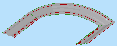
(1) A custom profile for modeling and (2) an object for annotation.
Profile:
In the profile editor
• The horizontal stretch extents are inside the fascia board reveals. This way, when you adjust the overall width the fascia thickness will be unchanged. Similarly, the vertical stretch extents go from the top to the underside of the soffit, leaving out the reveal.
The custom profile tech only allows you to stretch one dimension horizontally and one vertically. You can exempt parts of the profile from stretching, but you can't stretch them independently. If you want a different reveal depth or fascia thickness, you'll need another profile.
• Profiles can stretched bigger, but not smaller. (I call this a bug, but what do I know.) Any profile you intend to use with varying dimensions needs to match or be *smaller* than the smallest case you have.
• The templates have two profiles, Coffer Beam and Coffer Beam Half. Both are 4" x 2" which should be small enough. The half version has the fascia on only one side and is meant to be placed along a wall.
Remember that profiles are attributes, so they're within the project file, so you can edit them without messing up anybody else. And: You can use Attribute Manager to bring profiles into the current project from the templates.
Here is a sample condition at 1/4" scale, no detail added:
At higher scale, we need to add detail:
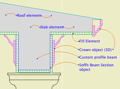
Object: Soffit Beam Section JM10
Location: 06 Wood & Plastic / 2D Wood
The object fits within the profile's perimeter.
• Height and width of the object will match that of the beam itself.
• Parameters for Fascia thickness and reveal.
• Crown Hgt sets the point at which the pen switches from the object's cut pen to the Separator Pen. In practice this height should meet the bottom of a crown object placed against the beam, which will maintain the heavy outline.
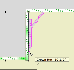
• The Half option uses one fascia board to work with the half version of the profile.
Commentary:
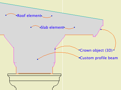
We build one model. We take views of the model and annotate them as needed. We will take views of the model at various scales. Scale is fundamental to architectural documentation: As we look closer, we see more.
Yet Archicad lacks any meaningful automatic scale sensitivity, except that written into objects by people who want it such as me.
In this example, see how the crown objects draw themselves as empty blobby things at 1/4" scale, but they're detailed shapes with proper fills at higher scales. The roof, slab, and beam elements, not so much. (Archicad library objects, not so much either.)
Since we can't get conventional AC elements to detail themselves according to scale (yet, I hope I hope), we need to build a model that can accommodate the detail we need to add. This is the idea behind something like the Stud Wall Detail object. The wall is empty, and we place the object in the viewpoints that need it.
The soffit detail described here has always been tricky. If you approximate the beam with a rectangular model, it's difficult to manage the reveal without masking. It's easier to add 2D detail than to subtract modeling.
A custom profile allows us to handle the cased beam in the "Empty Fill +" fashion we are accustomed to with walls, roofs, and floor decks.
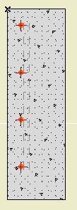
A 2D symbol to draw rebars in concrete structures.
Arrangement: Same as the Multiply command. Spread will place bars across the length of the object using the Spacing OC. Distribute will space the Quantity of bars evenly along the length.
You might use Distribute in a footing detail, where the spec would call for a number of bars, and Spread in a wall detail, where the spec calls for bars at a given spacing.
With the Spread arrangement, the end of the object is represented by a non-printing cross symbol.
Perpendicular Bars draws a pair of dashed lines behind the bar dots, representing the bars going the other way.
Coverage Hotspots places detectable points on the edge of the section dots at both ends. Use these spots to place the rebar object acurately and to dimension the coverage.
Graphic Crosses draws a cross through each bar to help with visibility.
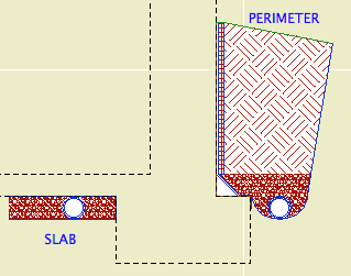
A 2D symbol for foundation perimeter drains and underslab drains in wall sections. In Perimeter mode, it draws the drain tile (pipe), gravel, cant strip, membrane, drainage board, and backfilled earth. In Slab mode, it draws the drain tile and gravel.
Dimensions (Perimeter version):
Height parameter: From the top of the footing to the top of the masonry ledge or grade level, whichever is less. If there's no ledge, the height will go to the grade and no board extension (see below) is needed. If there is a ledge, the height goes there and the extension streches to meet the grade.
Footing Width: Width of the footing beyond the wall, typically 6".
Cant Width: Width of the cant strip, typically 4".
Drain Diameter: Obvious
Drain Board Thickness: Obvious
Membrane Thickness: Needs to be enough to get the membrane/drain board edge clear of the heavy contour line of the wall. This will depend on the scale and line weights, but 5/16" seems to be a minimum. Be sure to check the printed output, not just the true weight on the screen.
Board Extension: In the masonry ledge case, the height added to the top of the object to meet grade level.
The grade line and backfill angles are controlled by the hotspot at the top right corner (left if mirrored).
The gravel depth matches the cant strip height, which is driven by the cant width.
The membrane overlap on the footing matches the radius of the drain.
The gutter is 2.5 times the drain diameter.
Dimensions (Slab version):
The gravel depth is defined by the drain diameter. The length is set by the Length parameter.
There is also a Drain Only mode which draws only the drain. In this mode the Filter atop the pipe can be on or off.
Attributes:
The Fill Pen is used for all the fills. The Outline Pen is used for the interior lines and the non-cut edges. The Cut Pen is used for the edges along the wall. (This way, the wall contour won't appear 'thinned' by the object.) The Grade Pen is used for the top lines. The grade line is usually one click heavier than the typical cut line weight.
The fills should be clear enough. But. In developing this object I realized that the proper fill for backfill earth had somehow slipped out of the templates. It's back now, but you should make sure you have the fill when you use this object. Use Attribute Manager and do the following:
• Go to the fills tab.
• In the right panel, click open and navigate to the 'NewHome10.tpl' in the zTemplate folder.
• In the right panel, scroll down until you see fills number 102 and 103. Highlight both of them.
• Click 'Overwrite' (not 'Append') in the center, then Apply, and confirm the modification.
• Close up the Attribute Manager.
The fill you want is '*Earth Backfill'. BTW, undisturbed earth should use the fill '*Earth'.
Improvement on the AC9 version to interact with the Floor Plan Cut Plane.
Turn on the 'Use Cut Plane' option.
This isn't a FPCP-comprehensive solution as you'd see with a conventional roof. It's still up to you to put the object on the first 'visible' story and show it one story up. On the story above, the object is drawn complete, with no FPCP interaction. Further, I'm not checking if the object is entirely above the FPCP; that's up to you to figure out. If the object is entirely above the plane, then it should be cut n pasted to the next story up. (If it is above the plane, it will be drawn as if uncut.)
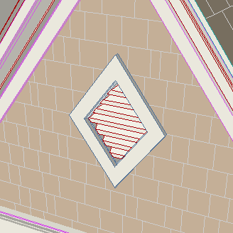
A diamond-shaped louvered gable vent.
It is designed with the assumption that will have the shape of the diamond follow the roof slope in most cases. Like many roof-oriented objects, you can choose the Roof Slope from a list or enter a custom value in Slope Angle. When you change either the height or width, the other dimension will adjust automatically to maintain the angle and thereby the proportions of the shape.
I think the rest of the parameters are self-explaining: Louver Thickness, Spacing, Angle, and Pen; Exterior and Interior Casing Width, Thickness, and Material.
The vent handles a masonry condition by setting itself into the wall by the sill dimension. (Use the 'second' Construction Method button.) The sill is drawn with the Masonry Sill Pen.
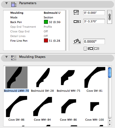
2D Moulding JAM9 is the current standard 2D moulding object. It is part of the whole moulding profile scheme, where I can add a new shape in one place and offer it for use in as many objects as we want. The Crown Tool, baseboard, rake, shed crown, door and window trim, etc., etc., are all hooked together. The 2D object offers all the shapes of all types.
I notice that a lot of people still use the individual shape objects in 06 Wood & Plastic / 2D Smoot. This doesn't hurt anything, but be advised that I don't use them and I don't maintain them, i.e., I don't make new ones. I can think of several reasons to use the old ones though:
• Habit.
• There's a shape in there that you can't find in 2D Moulding JAM9.
• You like seeing the shapes in the object browser.
The first one, you're on your own. The other two I believe I've covered with this revision.
I've gone through the old folder and incorporated all the shapes into 2D Moulding JAM9. I think. You'll let me know of course, just like you would if you needed a shape for the first time.
I made a graphical browser for the shapes.
I also reordered the list a bit. This is just a very cumbersome list. The current scheme is groups of:
• Crowns (including cove, rake, and bedmould)
• Casing (including fluting)
• Base (including cap and shoe)
• Panelmould (including nosing)
I hope it makes your shape choosing all that it should be.
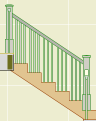
This is our 'stair helper'. As described here, I'm not a fan of all-in-one solutions for stairs or other complicated assemblies. I would rather build from discrete parts, each of which does its own job well. The main structure of a stair consists of slabs for landings and Stair Body objects for the flights. The railings and newels are separate.
The RiserMeter is one piece of the whole stair method complex. It performs several helpful tasks:
Make it Flat or not. If it's arched, you can set either the Spring Height or the Arch Height, and the other dimension will change to maintain the overall height.
You can show Joint Lines representing the stones, and set a Stone Max Width. The lines use the Joint Pen. (The lines on the old arch broke in AC10.)
Turn the keystone off by setting the Keystone Height to zero. The Key Base Width controls the width of the keystone. (At this time, the flat arch can't have a keystone.)
Jambs of two arches
The overhead lines (Cased Op Lines) can be switched off individually.
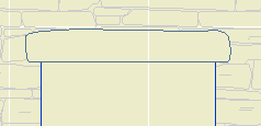
Two mitered blobs
Despite the version number, a minor update to the Cab Blob. Now you can miter it. No, they don't do that in real life; it's a 'blob' remember.
Also, almost unintentionally, this is the first 'important' object I'm no longer maintaining in AC9. There will be more of this going forward as 9 finally goes under for the last time.
Automatic titles are not new to 10, but title objects are new, and now that they are objects, we can use them, which is new.
A drawing title is essentially a marker for a drawing element. Like section markers, detail markers, symbol labels, and door/window markers, you choose the title from a popup menu rather than from an object-type browser.
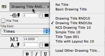
As with all markers, there's no way to restrict the list. It shows all the loaded drawing titles, and it's up to you to pick the right one.
Elevations, sections, site plans, and details should all use automatic titles. Plans are the only drawing which has an object (Plan Title RND10) in the window. PDFs placed for notes ordinarily shouldn't have a title. Scanned details might, it depends.
Since the title and its settings are part of the drawing element's settings, you can change them in groups using the Drawing Manager. (Note: You must have a layout as the frontmost window to do this; otherwise the title tab is grayed out.)
Drawing Title RND10a is very similar to Drawing Title RND9a. There's a couple of 10-specific changes:
• By default, the title uses the name of the drawing (which should come from the name of the view, which should come from the name of the window). You can put in a custom text under the 'Title' tab in the drawing settings dialog.
• Titles don't have a length parameter like a regular object. So the Length parameter controls the length. You would normally adjust this graphically:
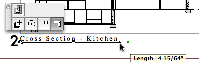
The length still has a minimum equal to the title text length.
Again I have to apologize for issuing a '10a' revision. There was one issue with Drawing Title RND10 that I couldn't fix in place. That title would appear right on the corner by default. The new one appears 3/8" below the corner, which makes it easier to move the title as needed. Note the 'move marker' palette button:
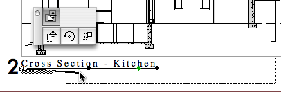
And, full disclosure, I broke the minimum length thing, but now that's fixed.
UPDATE 2007-12-11:
• You can set the Orientation of the title. You can have the title rotate to align with the Drawing (default), the Layout, or a Custom Angle. Use the Layout option to keep the title horizontal when you rotate a drawing. This is optional, and it's not always right. For example, if you rotate a wall section to fit on the sheet, the title should rotate too. I can't think of a purpose for Custom Angle, but it wasn't hard to put in there. If you do ever use it, the angle is graphically editable.
• You can choose a manual scale from a list. Leave the field empty to use the drawing's true scale. This is usually correct. To show no scale text, choose 'blank' from the list. You need to set a manual scale for a scanned detail PDF; now you can choose it from a list.
Location: 01 General / 5 Title & Layout
Very, very simple. A text showing a standard scale, which you can choose from a list. The primary use will be placement in the SK layouts' scale field.
Why? I don't like typing scales. And no, it's not easy to get the scale of the placed drawing automatically, though it should be.
Use it for SK addenda.
Options
A text object for writing the date.
If Auto Update is on, the date will be read from the system. (Tip: turn it on and then off to get today's date while keeping it from updating by itself tomorrow.) The Year, Month, and Day can be set manually using the pulldowns.
There are a lot of Date Format options. I've tried to cover all the conventions that I know of.
Any of the formats with a separator character will use the character given in Date Separator. You can choose from the list or make something up.
Two-Digit Day will zero-pad single digit days.
Day of Week can be on or off. If it's on, it will be read automatically along with the rest of the Auto Update. It will not fix itself for a manually set date. (It doesn't know the 30th is a Tuesday.) The Format of the day of the week can be long or short. Note that the list will always give the short form. The day of the week can be followed by an arbitrary separator, where the default is a comma.
You can add Leading or Trailing Text.
Text Formatting: All the usual suspects. Font, size. (You can choose mm or points to define the units.) Bold, italic, underline. The object can be anchored by any of the nine typical text block spots, using the Horizontal and Vertical Anchor parameters. You can have a Background Pen and the Outline Pen. Setting either one to zero turns it off. Finally, you can set the Padding between the text and the background/outline polygon. (This uses the same units option as the text size.)
Non-locals who would like to try it out can download it here.
Kinda silly, but.
You can turn off the fluting in Fluted Column JM9. You normally wouldn't do this. You would use Tuscan Column JAM8. But that column doesn't have the option of turning off the base. So if you need a smooth column with no base, use a fluted column and turn the base off.
Someday I'll add a base switch to the Tuscan Column, but this was an easier quick fix.
Location: 06 Wood & Plastic / Columns & Pilasters
Original here.
Added the ability to extend the side fill along the ceiling on either side, even at an angle.
The spot at the end stretches the length, and the spot in the middle adjusts the angle.
A rectangular or arched shape for subtracting niches into walls.
If the Arch Height is zero, the top is flat. The Wall Pen draws a heavy line around the back of the niche, to match the weight of the wall's contour.
The side with the center node should go along the edge of the wall. That side is drawn with the object's pen.
The idea is to SEO subtract the object from the wall, as discussed here. You can use a window to cut a niche, but the subtraction gives you better display control.
You would typically place the object on the layer X SEO Show2. This is the layer for SEO operators that show in plan only. (In 3D views, you would see the niche, but not the operator itself.)
You might need to bring the object forward to make sure it masks the wall. The parameter Edge Nudge helps make sure the lighter edge line of the object covers the heavier wall contour line underneath. Turn on True Line Weights to check it, and increase the nudge as needed.
Download (AC10)
A minor tweak of the venerable rod and shelf. If Wall Line is on, you get a line at the back of the object, drawn with a dedicated Pen. This pen should match the pen of the wall. The new parameter is on by default with pen 15.
Why. Because if the shelf's plan fill is on, it tends to obscure the wall's contour. You could correct this by bringing the wall forward, but now you don't have to.
Historical note: As far as I can tell, this was my first object in GDL, with a date of 9 August 1999.
Everything in Stair Body JM9a still applies.
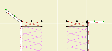
Major feature added: You can choose to have the stair cut by the Floor Plan Cut Plane. Recommended.
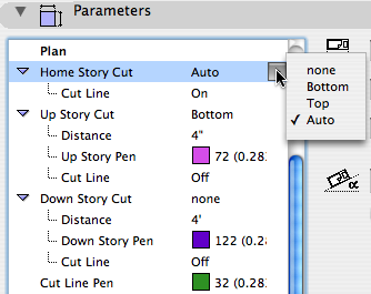
With the 'Auto' cut setting, you can choose to show a Cut Fill instead of the cut line. This will show the true cut thickness of the stair, similar to the roof element behavior.
Minor feature added: Separate cut line switches for the above and below stories.
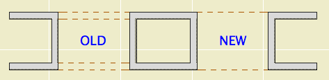
Two parameters added to the 'Plan' options in the Interior JAM9 door, so you can turn off either side of a cased opening. The parameters are 'Cased Op Line (Swing)' and 'Cased Op Line (Opp)'. Both are on by default. (Note: You will only see them in the parameter list, not the interface pages.)
This feature address this condition, where openings in each of two walls are supposed to look like one thick opening:
Swing = the clicked side when the door was placed. Yes, it can be tricky to tell which is the swing side of a cased opening, but there's nothing else to call it. If one switch doesn't do what you want, try the other one.
I'll probably add this feature to all the threshold lines when I next update the doors, which will be after the transition to 10 is complete.
(Again, pardon the 'a'. Some things can't be fixed in place.)
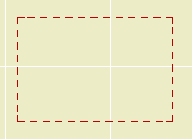
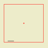
This object represents the available area of a detail sheet grid cell, or group of cells. Use it in your details to plan how the detail will lie in the cell. Very similar to Sheet Area RND10, which is used for plans.
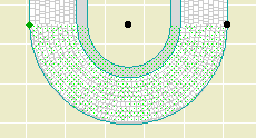
Turn on the Cover Fill to make the pieces opaque (White, pen 91). Useful for roof plans of a pergola. Stories below will not show the fill.
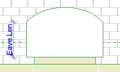
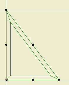
I Added an 'Eave Length' parameter to the plan options. This allows you to show a straight eave before the curve begins:
I also made the plan fill a cover fill, so it will respect the display/model view options.
Location: 01 General / 1 Graphic Symbols
A custom drawing title object for plans only. It's very similar to the old Drawing Title RND 9a.
As you know, in AC10 we use the new automatic drawing title marker objects. All drawings except full size plans should use the automatic titles.
Why do plans still use an object? Because we want the titles to stack through the sheets, and the best way is the multi-story feature of conventional objects. There's no easy way to align elements across layouts.
Since we're sticking with the object for plans, and not using the object for anything else, I decided to optimize the object for plans, so here we are.
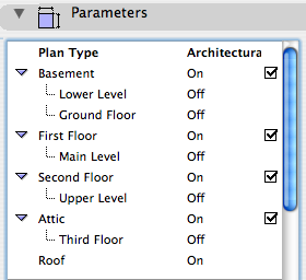
In the templates, there is one of these guys for each plan. In setting up the project, you need to set up the plan titles. For example, turn the attic off if there's no attic. The best way to do this is all at once: Turn all the note layers on, select all the title objects, and change their story setup.
The different names for a given story are all hooked together, so if you turn 'Main Level' on, 'First Floor' will switch off.
Place the object on the lowest story that is in use. If that's the basement, turn 'Basement' on. If not, turn it off and 'First Floor' will take its place. Etc.
Location: 01 General : 1 Graphic Symbols
Replaces Elev Marker JM9. It's been bi-axially flipped around to make it more standard. The circle gadget is on the left, where it belongs, and the description is on the top, where it belongs.
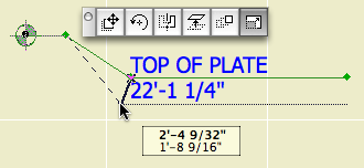
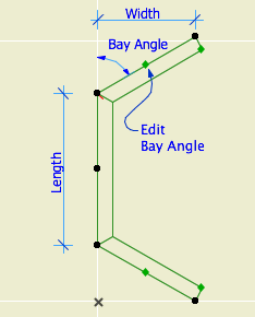
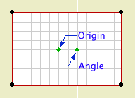
Editing hotspots
First spot: beginning of bend. Second spot: End and depth of bend. End spot: depth of bend and length of object.
The length can be input directly with the Length (Paper) parameter. 2" is standard.
Archicad 10 provides automatic story levels in section, but you'll still need this object to call out other levels.
Location: 01 General / 1 Graphic Symbols
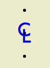
If you're local (in the same room), this won't make much difference to you. I have generalized the old CL symbol so I can offer it for download on the new Archicad Talk Object Depository. This means I'm enabling flexibility which I, and the locals, don't need.
For everyone else. This is your basic CL symbol, since most fonts don't have it. You can change the font and size, and apply bold formatting. Now I'll copy and paste the helpful commenting from the 2D script:
!! The default font is Arial, since that
!! seems to be the default font of the
!! universe. If you have Gill Sans, use
!! that. It looks best IMO. It's the font
!! in the preview image. Full disclosure:
!! I'm not into the faux-hand lettering
!! thing.
!! If you put in a custom font, and you're
!! graphically particular, you might need to
!! adjust the Text Offsets to get the right look.
!! The top & bottom hotspot offset is
!! proportional to the point size. I don't
!! know what happens with very large sizes;
!! you might need to adjust 'spotY' as well.
!! Personally, I never mess with the size; I just
!! put it in for completeness.
!! Why aren't the offsets parameterized?
!! Because you shouldn't change them for
!! specific instances. They should be standards
!! that are invisible in regular use.
Placement tip: Set the object to insert by the top or bottom hotspot, and use the Rotated geometry method of the object tool.
Download (AC9)
Location: 01 General / 1 Graphic Symbols
An improved drawing list object, featuring any number of columns. You can also turn the heading off entirely. I ditched the vertical lines.
Two things you need to know. We are redesigning the standard cover sheet, and we have a couple of projects where the drawing list needs to be three columns in order to fit in its box. And, in 10, we have automatic drawing lists, so you're going to use the object only in unusual situations. (Too bad, it's one of my favorites.) With the auto list, the heading needs to be independent for technical reasons. For compatibility with the auto list, and the new cover sheet, we need to be able to turn the heading off.
All of this will make more sense when you actually start using 10. In the meantime, if you need to spread the drawing list over eight columns, go ahead.
Update: The 10 version is better.
Location: 01 General / 1 Graphic Symbols
(Any non-local people who would like to try it out, it's here.)
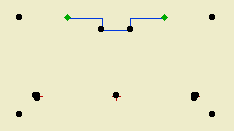
The elusive masking cutline. Then I started adding a bunch of other stuff, hence the strikethroughs in the title. Here's its simplest form:
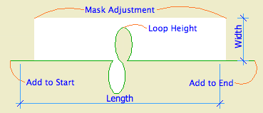
Check out how the arrows don't step on the text.
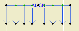
The alignment symbol. Slightly improved from the JAM8 version: You can have more than two arrows, up to a total of eight. That should be enough. For the extras, you can turn on Equal Spacing, or locate each one individually.
Location: 06 Wood & Plastic / Railings & Stairs (I'm thinking about moving it, since it's not really a fine detail-type thing any more. More like a missing tool thing. Not to mention, it could be concrete. I really wish the object browser could handle aliases. As for now, there it lies.)
UPDATE: Stair Body JM9a is exactly like Stair Body JM9, but I added the story-sensitivity behavior from Railing JAM9. See below.
In honor of the story cuts, I also added an integrated cutline. It is simplified, and it still doesn't mask, but I'm working on that.
I also (now how much would you pay) added a Cover Fill Pen parameter, which simply allows the object to be opaque.
All this is identical to the JM9 post otherwise.
(Teaser futuristic update-to-be: I am already mostly done with Stair Body JM10, believe it or not. The big deal there is intelligent interaction with the new Floor Plan Cut Plane. Pretty cool.)
A very basic (in a good way) flight of stairs. An incremental improvement on Stair Stringer JAM8. You can still use it as a stringer; just make it thin. I changed the name because I use it more often for actual stairs.
Sidebar: There's a stair tool (Technically, the StairMaker add-on), which you should never use. Then there's ArchiStair by the very capable and friendly Cigraph, which is like a good StairMaker, only better.
I recently used an ArchiStair spiral stair for which I was very grateful, but generally I am skeptical of full-service add-ons for highly detailed building parts. No matter how many options, configurations, and details are offered, you will soon run into a custom situation where the add-on doesn't quite make it.
I would rather have more, simpler, separate elements. (Well, no, I would rather have one element do everything by magic, but it's not realistic.) If you run into a freaky custom railing, you can focus on that without wrecking the whole stair. And: In design development, you can show just a simple stair, leaving the details for later, where they (the details) belong.
This is consistent with a general principle of Archicad's design, our workflow, and how projects are actually built. Big, chunky stuff comes first: Walls, slabs, roofs, the basic geometry of stairs. Fine detail comes later, and is applied to the big stuff: Trim, finish floors, newels and railings.
So: The Stair Body object is like a slab tool for stairs.
Another major basic-yet-detailed building part is the chimney. See what I mean? End sidebar.
Now we can talk about the object.
I found this 90% finished in the Ice folder, so I wrapped it up. The main difference is that the text expansion is now handled as a real number, consistent with the expansion feature of text in AC. The default expansion factor is 2.0.
Also: All the drawing names default to Title Case instead of ALL CAPS. Listen, all caps is played. It's a holdover from the hand-lettering days, which I barely remember. Nobody else in any print, design, or writing field uses caps all the time just because. It is hard to read. It looks like shouting.
Played.
Also, in the future (I'm optimistic), we will use automatic drawing titles. (Yes, they can be automatic in 9, but they're not parametric, and they don't cut it.) The name of the SE marker will be the name of the drawing. I'm not going to look at a Navigator full of CAPS all day.
Bury all caps, not praise.
This is a placeholder, I'll flesh it out eventually.
Exterior JAM9 is the new all-(most-?)purpose exterior door. It makes obsolete a large number of JAM8 doors, I don't know how many. Most of the 'basic' parameters (single/double, transom, leaf style, etc) which used to have separate door objects, are rolled into this one. Briefly, more later:
• Single or double
• Solid, french, or glazed-paneled leaf
• Side lights on either side, both, or not
• Transoms with various relationships to the door and side lights
The masonry and trim settings are very similar to the old doors, with greatly improved scale sensitivity in the profiles.
The JAM8 doors have been moved to 08a Doors/JAM8 Doors. They will continue to work. You 'shouldn't' need them. If a feature is missing in the new door, or if you encounter other problems, please let me know.
Location: 13 Special Construction
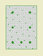
For adding shingle-style swoops to walls and roofs.
UPDATE: It's swoop JAM9a now. The previous version didn't slope right sometimes. Also, the Width parameter now applies to the bottom width, not the overall width.
Location: 03 Concrete
A 2D symbol to lay over a footing rectangle, in wall sections, for example. It can draw the rebars, the notch for the foundation wall, and the lines at the edge of an adjacent slab. It can draw the outline of the footing, as well as the fill, but for most cases it shouldn't be needed. I put it in there for completeness.
The height and width should match the footing.
Rebars: Set the size, quantity, side coverage, and bottom coverage. Hotspots are provided for dimensioning the coverage. Graphic crosses can be turned on to make the bars easier to see. Turn on 'Other Way Bars' to show dashed bars going the other way.
The thickness of the wall and the adjacent slab can be edited graphically.
UPDATE: I added an option for sealant at the slab edge. You can set the thickness and the fill.
Normally there would be, you know, a footing.
2005-03-23
2005-12-06
A window. Location: 12 Furnishings/Casework
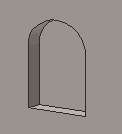
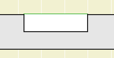
Basically, a niche. I guess you could use it for a wall niche too, with the usual caveats.
But the real idea is to build a bookshelf or cabinet etc from a thick (11"?) wall:
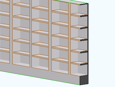
I marquee'd it so you can see the back.
Location: 01 General / 3 Drawing Tools
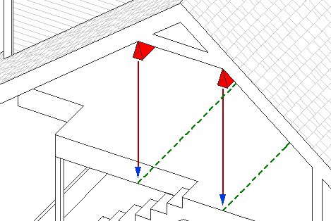
To help locate overhead ceiling lines. This is a little weird but you'll get it.
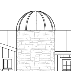
Location: 13 Special Construction
An alternative to Archicad's dismal, so-called vault. Last time I saw so many lines, it was election day in Ohio! Anyway.
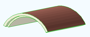
This is the main, simple text label for associated labeling of objects. It has one parameter, "Parameter to List". Put in the variable name of any text parameter in any object. The default is "desList". I'm using this name as a standard in many objects across the library. So you can put in any parameter name, but for many typical cases you can leave it alone.
Some objects will need more complex, customized labels, which we'll develop as we go along.
(To find the variable name of a parameter: Select the object you want to label and press Cmd+Option+O. (File -> GDL Objects -> Open Object) Find the parameter in the parameter list in the master window. The variable name is the first text column. It's an unfriendly-looking (probably) word-like thing.)
Objects that can be labeled using the "desList" parameter:
Wood Beam JAM9
Column Wood JAM9
Column Steel JAM9
Steel W Shape JAM9
Bent W Shape JAM9
Tuscan Column JAM9
RiserMeter JAM9
UPDATE: I added a list to the 'Parameter to List' parameter. In addition to desList, there's 'typeList', the 'Type for List' parameter of the crown tool, where you can put in a description of the crown, such as 'Type 1'. There's also 'crnDes', which is the name of the crown shape in the crown tool. With these parameters, you can label crown elements in the RCP.
You can still use any parameter name, not just the listed ones.
I also added a read-only description of each of the listed parameters.
Original date: 2004-12-15
Location: 06 Wood & Plastic / Trim & Moulding
A sloped crown object for shed roofs. It's similar to the Crown Tool.
Sorry about the 'a'. I found an issue I couldn't fix in place, so I had to make a copy.
Location: 05 Metals
(Old object, new write-up.)
An object for modeling and annotating W shape steel members. It should behave similarly to Wood Beam JAM9. So I can copy and paste a lot of the documentation. Also, that post has screen shots.
Location: 15 Mech-Plumbing
A very simple residential water heater. OK, it's a cylinder.
The reason to use it is it knows an array of standard capacities, and the tank dimensions for each. You can stretch the object in plan or 3D to change the size. You can also enter a custom size and dimensions.
In plan, the circle can be labeled with the capacity, or just 'WH'.
It's a slight improvement on WaterHeater JAM9; note the subtle spelling difference until I move the old one.
Obsolete. Use Stair Body JM9a. instead.
Location: 06 Wood & Plastic / Railings & Stairs (I'm thinking about moving it, since it's not really a fine detail-type thing any more. More like a missing tool thing. Not to mention, it could be concrete. I really wish the object browser could handle aliases. As for now, there it lies.)
A very basic (in a good way) flight of stairs. An incremental improvement on Stair Stringer JAM8. You can still use it as a stringer; just make it thin. I changed the name because I use it more often for actual stairs.
Sidebar: There's a stair tool (Technically, the StairMaker add-on), which you should never use. Then there's ArchiStair by the very capable and friendly Cigraph, which is like a good StairMaker, only better.
I recently used an ArchiStair spiral stair for which I was very grateful, but generally I am skeptical of full-service add-ons for highly detailed building parts. No matter how many options, configurations, and details are offered, you will soon run into a custom situation where the add-on doesn't quite make it.
I would rather have more, simpler, separate elements. (Well, no, I would rather have one element do everything by magic, but it's not realistic.) If you run into a freaky custom railing, you can focus on that without wrecking the whole stair. And: In design development, you can show just a simple stair, leaving the details for later, where they (the details) belong.
This is consistent with a general principle of Archicad's design, our workflow, and how projects are actually built. Big, chunky stuff comes first: Walls, slabs, roofs, the basic geometry of stairs. Fine detail comes later, and is applied to the big stuff: Trim, finish floors, newels and railings.
So: The Stair Body object is like a slab tool for stairs.
Another major basic-yet-detailed building part is the chimney. See what I mean? End sidebar.
Now we can talk about the object.
For cutting a limited chamfer in a corner of something. Or unlimited, but you could do that with a slab. Use it with Solid Elements subtract.
By default, it's vertical, but you can use any Slope between 0º and 90º. If the object isn't vertical, you can also set a Rotation angle. (If it's vertical, you just rotate it in plan.)
Even if the object isn't vertical, the 'length' of the cut is controlled by the height parameter. This is a little awkward, but it's made less so by having the length stretchable at any angle.
For sloped cutters, it is highly recommended to throw them down and fix the placement in section. To do this, you need to temporarily switch the SEO layer to solid in the layer dialog. In wireframe mode, you can't tell where the object is cut by the section, so you don't know where to grab it.
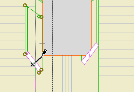
Grab the object by the midpoint, and drag it to the corner.
The thickness of the object is the standard width parameter. Often you will have a dimension for the cut along the face of the element being cut. For this, use the Ortho Cut Length parameter. This parameter and the thickness are hooked together, so you can use either one. The Ortho Length is editable in plan.
Using a bunch of these objects I made this:
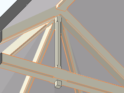
I also used it on the newel module thing.
May 9, 2008 update:
In the image above, the vertical piece was done using four separate objects. To simplify this move in the future, I added a parameter for Multiple Corners. This will arrange up to four cutters in a rectangular pattern defined by the X and Y Dimensions.
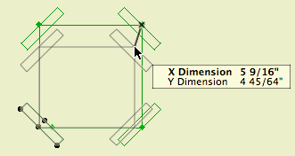
Place one of these and tilt it, and you can chamfer the strut of a bracket:
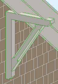
Download (AC11)
Location: 04 Masonry
Put these on the corners for that authentic Potomac builder puffball look. Or maybe you could use it for a nice house, who knows.
Pretty simple; length, width, height, thickness. The Form can be Stack or Stagger. Stagger is the alternating one.
Stack...Stagger...Stack...
If Stack is selected, you can set Symmetrical to on or off. When on, it causes the width to equal the length.
If it were me I would use the layer F Trim Ext Mid. Place one object to cover all the affected stories.
Location: 06 Wood & Plastic/Columns & Pilasters
A decorative column or pilaster, with an optional panel, and mouldings for the top, base, and panel.
Location: 06 Wood & Plastic/Brackets
A bracket that looks like this:
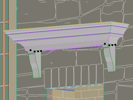
You can set the width (X), thickness (Y), height, height and depth of the nose, and width of the base. That's about it.
(By the way, the arch is slabified.)
Location: 06 Wood & Plastic
One, or many, rafter tails or pergola elements. A huge improvement over Rafter Tails HOOV8.
Location: 01 General / 1 Graphic Symbols
This one has square, rectangle, triangle, circle, ellipse, oval, diamond, and hexagon.
The rectangle, oval, and hexagon will elongate to accommodate the text, if the Stretch for Text parameter is on. The square will turn into a rectangle.
The Height parameter refers to the vertical dimension. The Length Factor parameter is multiplied by the height to get the length of the rectangle, ellipse, and oval shapes. If Stretch for Text is on, the length is overridden by the text length.
The text, by default, is the global ID of the object. You can also choose to enter a custom text.
The size of the text can be set by points, millimeters, or as a fraction of the shape height. All these parameters are hooked together, so when you switch among them the actual height stays the same.
There is a value list for the font, and you can enter any font name. The text can be shown bold, italic, underlined, or any combination.
Update 2007-12-13: The Mask parameter will make the shape opaque white, using the 'Solid' Fill and White Pen parameters.
I'm making this object available for download on Archicad-Talk. (Hence the mm size option.)
Or download here.
Location: 06 Wood & Plastic/Trim & Moulding
This has been deployed for some time, but here's the 'documentation'. It may or may not tell you something you don't know. I have also fixed a couple of minor glitches and finished the custom interface page, finally.
Location: Doesn't matter; window & door markers are selected from the flyout in the info box or the 'dimension marker' tab of the settings dialog.
WindowTag: When the ID doesn't fit in the regular hexagon, the shape elongates to accommodate it.
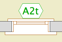
DoorTag: I fixed that upside-down text thing, I'm pretty sure. I took out the Flip Text parameter. If it gives you any trouble let me know.
Update. The AC11 versions have RCP-awareness.
Location: 13 Special Construction
Two objects (primarily) for cutting coved recesses into ceilings, using solid element operations. One's a circle, one's a rectangle. Guess which is which. The parameters of each are similar.
The fillet radius must be less than or equal to the height. The resolution of the fillet is controlled by the Fillet Facets parameter. For the disc, the Resol parameter controls the resolution of the circle.
You can turn the objects upside-down with Flip Z. I can't imagine many cases for doing so, but you never know.
In practice, your ceiling slab will be the target, and the object will be the operator.
Location: 06 Wood & Plastic/Trim & Moulding
Exactly like the other recent panel objects. This one is a parallelogram suitable for going along stairs. It's a window, and should be used with a thin wall.
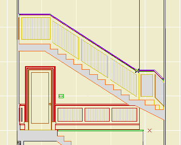
The height is the height of the vertical sides, not the overall height.
The slope can be set either by entering the angle or the rise and run. Note: Stair Stringer JAM8 knows its angle in degrees. You can copy it from the settings and paste it into the panel's settings.
It's one of those things that's easier to edit in a section window. Remember windows and doors can be stretched and copied in section.
It looks slightly different in plan from Trim Panel JM9. The handle lines point in the downward-sloping direction.
Location: 06 Wood & Plastic/Trim & Moulding
Identical to Trim Panel JM9 and Trim Panel Ceiling JM9, except it's a skylight. And since it's a skylight, it can only be rectangular.
(Q: Why don't you give the ceiling version a slope parameter, then we could subtract from roofs and have all the shapes? A: Good idea, but you can only subtract straight down. You would need to subtract in an angled direction. A wish.)
The 'height' is stretchable in 3D. The height is stretchable in plan too, though the plan view is foreshortened. Further, the plan image shows the shape at the bottom of the roof, what you'd want to see in the RCP. But the hole in the roof is displayed as seen from the top; they won't align, don't worry about it.
Location: 06 Wood & Plastic/Trim & Moulding
Identical to Trim Panel JM9, except it's an object instead of a window, and it lays flat.
It's for putting panels in slabs, for ceilings.
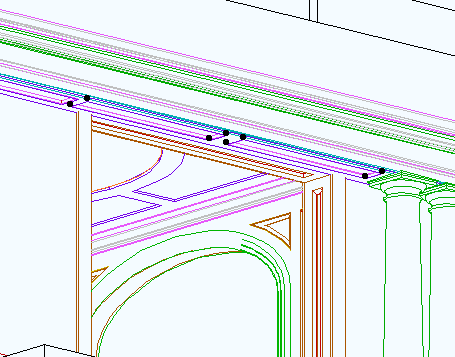
No, it can't actually cut the hole. You have to do that, using SEOs. Target: slab, operator: panel object. Subtract with downwards extrusion. (There is evidence of a SLABHOLE capability in AC, but it is not realized.)
You can choose to show it in the RCP by putting on the layer F Trim Crown.
The 'cut' shapes are editable in plan.
You can show a fill inside the plan polygon.
Location: 06 Wood & Plastic/Trim & Moulding
Actually a window. For placing panels in a thin wall, which would be the casing. Use a 1" thick wall for 5/4x, and 3/4" for 1x.
The object is based on Panel Hole JAM9. The difference is the addition of other shapes. This renders obsolete Panel Hole Int Trapezoid.
Each shape can point up or down (Orientation parameter). The available shapes are:
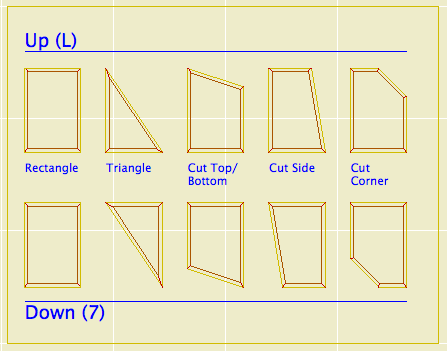
If you want to flip side to side, you need to mirror the window itself.
All these shapes are based on a right angle. If you need irregular triangles, let me know, I would probably do a separate object for those. I am working on an arbitrary-polygon drag-and-drop panel, but it isn't done.
You are encouraged to suggest other shapes. An octagon would be very simple if anyone needs it.
There is a selection of surround mouldings, including 'none'. The panel itself can be modeled or not, and if it is modeled it can have a thickness of zero (like a coat of paint). The panel can be raised or flat.
You can turn off the moulding and the panel and just have an empty opening.
If you choose any of the 'cut' shapes (Top/Bottom, Side, Corner), you can set the cut distance or the cut angle. The angle is useful when placing a panel under a stair or roof. The angles and cuts should intelligently when one or the other is changed.
You can choose to cut the actual hole with the object's pen or the wall's pen (Cut Pen parameter). Panels should have a weight of 2 (22, etc). For interior panels, you can make the wall this weight, and use the 'Wall' pen setting in the panel. On the exterior, the panel wall should be a 3 weight, and the hole should be cut with the object's pen, which should be a 2 weight.
In plan, the window has two red line 'handles' to make it easier to select. You can drag the window by these handles, but unfortunately you can't stretch.
At larger scales (3/4" and bigger), the moulding will show a wood fill in section. Otherwise, it will show the object's main fill. I'm working on getting the scale-sensitive fill thing in all the trim objects.
To these you can add:
Align Symbol JAM8
Drawing Title RND9
Elev Marker JM9
Joist Note JAM9
Note Column JAM9
Footing Stepped JM9
Stud Wall Detail JM9
Gutter JAM8
Insulation Batt MTL8
Rod+Shelf JM9
Railing JM9
All the wood and steel beams
Anything made from the Miter Object Template JAM9
If you see an object that should have detectable edges and doesn't, let me know.
Location: 01 General : 1 Graphic Symbols
An incremental improvement to Elev Marker JAM8, which it replaces. The 'bending' is now handled by editing hotspots.
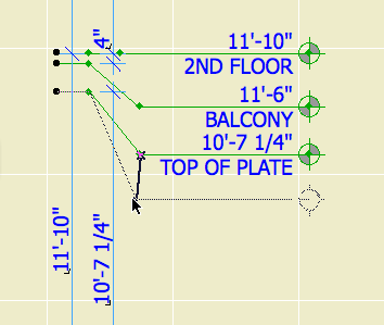
First spot: beginning of bend. Second spot: End and depth of bend. End spot: depth of bend and length of object.
Somewhere along the line I added the ability to display the elevation relative to sea level as well as project zero, without telling anyone, so now I've told you.
Location: 06 Wood & Plastic : 2D Wood
This object makes it easier to fill in stud walls in wall sections. It combines plates, headers, blocking, drywall, sheathing, and insulation, in any combination, for 2x4 or 2x6 walls.
At the top you can have a plate, double plate, or nothing. The bottom has these options plus a header, and an optional anchor bolt for the plate.
You can show batt insulation or not, and show mid-height blocking or not.
Outside the studs on either side you can have a fill for drywall, plywood, or neither. The perimeter line on both sides is optional. If you are placing the object in an existing wall, you usually don't need these lines.
This object is another aid to developing wall sections while keeping them model views. If there's anything it could do that isn't, let me know.
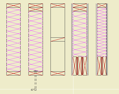
UPDATE 12-22-06: Added the ability to extend the side fill along the ceiling on either side, even at an angle.
The spot at the end stretches the length, and the spot in the middle adjusts the angle.
A label to show the elevation of the top or bottom of a slab.
It works in plan or in section, and changes its form depending on which kind of window it's in. It can give the elevation to project zero or the home story of the slab.
I made it in an attempt to overcome one of the big limitations of the Level Dimension tool: It can't read the bottom of an element. If you can read the bottom of an element, you can show live ceiling height dimensions in the RCP. I'm also attempting to overcome one of the big limitations of the level version of the regular dimension tool in section: It isn't truly associative and doesn't move when the slab does.
In creating this label, I discovered and did mortal combat with several disabilities in Archicad, and especially in the label functionality. In the end, it doesn't do nearly what I want it to, but it's (mostly) not my fault. The section version works well for showing ceiling heights, as long as the slab is on the same story as the room. To use the plan version in RCP, my original primary goal, involves additional layers, or commits me to fussier modeling of ceilings than is otherwise needed, and is tedious to maintain.
(I wrote a mini-white-paper mapping the related Archicad disabilities on Archicad Talk, if you're interested, here it is.)
So even though the plan version has three broken legs, the section version is passable, so here it is.
Use it as an associated label, of course. Choose to label the top or bottom, to project zero or the home story zero.
In plan, you should only use it to label the bottom of a slab; for the top, the level dim is far superior, since it can read hidden elements.
The plan text can moved anywhere, and will flip around depending on what quadrant it's in. Sorry about the separate X & Y editing hotspots, for some reason they can't coincide in labels. I regrouped and got it working; the current version is for AC10 or above.
When placing the label in section, it will always appear at the lower left corner of the slab. If you are dimensioning the top, you need to move the label manually.
Download (AC10)
Location: 01 General : 1 Graphic Symbols
Very similar to SectElevDetail Marker JAM9, with the improved autotext handling discussed here.
Same as with Detail Area JAM9, paste just the gibberish part of the autotext from PlotMaker into the "Paste Autotext Here" field. The drawing name and number will fill in. If you are using the Double Section symbol type, paste the data from the other drawing into the "Paste Autotext 2 Here" field. If the drawings are on the same sheet, as they usually will be for a pair of sections, leave "Same Sheet Number" on. If you turn this off, the second sheet number will be generated from the second pasted text.
Once I put up that screenshot of the detail marker, I noticed that the gibberish components of the two autotexts are the same. The difference lies in the DRAWINGNUMBER_R and LAYOUTNUMBER_R tags at the front.
This means I can have reference markers (section and detail flags) that just need to be told the gibberish segment once, and can build the autotexts themselves. For these objects, instead of copying the entire autotext in PlotMaker, just copy the data within the second pair of angle brackets: "<9BEA5D4E-8700-11D8-8AA9-000A95A7B33A>".
I have added this ability to Detail Area JAM9. In the settings, paste the gibberish into the "Paste Autotext Here" field. In the drawing and layout number fields above, you will see the completed autotext fill in. You can still put non-auto text in these fields; if you delete the "Pasted" data, the fields will empty and unlock, and you can use them however you want.
For labeling doors and windows in section/elevation. This is completely different from the dimension marker used in plan.
It is intended to be used as an associated label.
How about a quick review of associated labels. To place an associated label, select the element, in the window you want the label, and Check 'label Elements' in the Info Box. Which label will be placed? Ah. Each tool has default label settings, which are configured in the Label settings dialog. For each tool you want to label, highlight it in the list at the top and choose the appropriate label from the top right flyout. This is also where you set the pen, layer, and other attributes of the label. Remember that labels can have a different layer than the elements they reference, and they usually will.
For doors and windows, starting today, set the label tool to use Door-Window Label JM9.
It draws a hexagon for windows and an ellipse for doors. It knows the difference! If Auto Size is on, the window tag will be 5/16" and the door tag will be 3/8". If these don't meet you needs, turn Auto Size off.
Once the label is placed, move it where you want it. (A method to control where labels pop up remains elusive.) Place the label on a sash with no divisions, or to the side of the window/door. Try not to obscure the design of the window/door.
See also:
Labels
Location: 06 Wood & Plastic / Structure
An object for modeling and annotating wood structure elements.
Location: 03 Concrete
The main parameters are the height, width, and thickness.
By default, the overlap matches the thickness, and the tread is double the thickness. To change either value, set the parameters to other than zero.
The length of the object cannot be controlled. The idea is to let the object tell how much length is needed to step up the required height. The resulting length is the distance between the adjacent slabs. The length is shown, locked, in the length field.
The object "starts" at the bottom. When the length changes, the top end moves.
The top of the object will match the top elevation of the upper slab footing. The bottom, it depends:
If meeting the lower footing "in line", the bottom elevation should match the top of the lower slab, and the "Bottom Lap Segment" should be on. If meeting the lower slab at a "T", the bottom of the object should match the bottom of the slab, and the lap segment should be off. I think the second case is more typical, and is shown in the image below.
The "length" rectangle is shown with the floor plan pen of the object. The adjacent slabs should meet the ends of this rectangle. The red line indicates the bottom of the object, and the extent of the Bottom Lap Segment, if on. The light pink line shows the physical extent of the object at the top. Both these lines print white. The lines in between represent the elevation changes (steps).
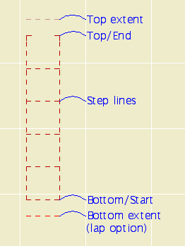
In plan.
Placement: The object should be drawn with a dashed line. I suggest using a different pen from your footing slabs, with the same weight. Use the layer S Footing. Set the bottom elevation first, as described above. Next, set the top elevation. The object will extend to accommodate the needed "treads". Then adjust the upper slab to meet top end of the object. (This end is represented by two small lines instead of a full line, so it doesn't interfere with the end line of the slab.) Whenever you change any parameter of the object, you will need to adjust the top slab too.
Cutting the foundation wall: The wall which sits atop the object should extend to the edge of the top slab. The wall's base should be at the top of the lower footing. Subtract the object from the wall with downward extrusion. Without SEOs, this object wouldn't be possible.
Cutting the wall.
Location: 13 Special Construction
When using a thin wall for casing or paneling, a window for cutting the outside of an arch casing. You can set the height and the width. You can choose to extend the hole on either side of the arch to cut more wall.
Like the Openings in the Archicad library, you can preview the shape of the window in the settings box elevation view.
Here's what it's for. I used an Archicad library arch opening for the inside.
Location: 06 Wood & Plastic : Railings & Stairs
This is essentially the same as Newel STUM8. It has a cap and a plinth. The only thing I added is the ability to have a different pen when shown one story up, so it can match the behavior of Railing JM9. I figured you wouldn't show it on the story below very often.
Location: 01 General : 1 Graphic Symbols
I actually updated this about 3 months ago. The only differences from the previous version are the addition of the Z shape option, and the ability to flip the direction in plan, using the hotspot above (UP) or below (DN) the direction text.
Location: 06 Wood and Plastic / Railings & Stairs
Here's a new railing object. It should be the only (simple) one you need, since it can be interior or exterior, and level or sloped.
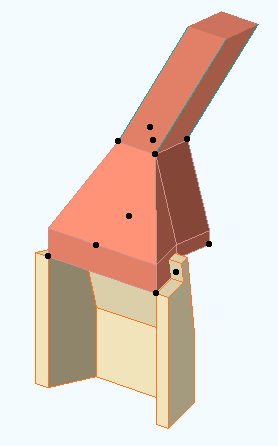
Location: 04 Masonry : Chimney & Fireplace
The missing link between Firebox JM9 and Flue JM9. You could use a mesh and a slab in its place, but why?
The smoke chamber fits on top of the firebox. The width, depth, and firebox Back width should match the Firebox Lining object. The flue width and depth should match the Flue object. The front of the flue lines up with the back of the firebox. You can't change this.
The throat height is the distance from the top of the firebox to the start of the smoke chamber slope. The shelf depth is the distance from the slope start point down to the bottom of the smoke shelf, behind the firebox. The throat adjustment is for hiding the edge of the smoke shelf inside the top of the Firebox Lining. (Very easy to see in section image below the fold.)
The object should be placed on the layer A Flue. Model it with a visible, white-printing pen such as 40. For the material, use the material you want to see inside the flue. The Flue Pen should be a printing pen, to show the start of the flue above.
More images below the fold.
Location: 04 Masonry : Chimney & Fireplace
Just the fire brick part. Looks good in plan, section, and elevation. For a correct section, align the polygon wall of the firebox core with the inside of the Lining object, then subtract the object from the wall.
Images below the fold.
Location: 04 Masonry / Chimney & Fireplace
A round or rectangular tube for modeling chimney flues. The top can be offset for a sloping flue.
Plan Display & Editing
"Show Cut" means a white box with a X. "Show Slant" means the path of the sloping flue, typically shown dashed. Both can turned off, in which case the object will be invisible, but the nodes will remain. The cut polygon can represent the top or bottom. The flue size is stretchable by any corner. The top offset can set by stretching the green node.
3D Editing
The offsets and the height can be edited with the green node in 3D.
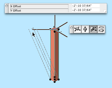
Offset stretch in 3D
General use
The idea is to build the flues out individual segments using the object. Use the layer A Flue. Subtract the flue objects from everything they pass through. When subtracting, use "Inherit attributes of operator".
The layer A Flue should generally be set to wireframe.
I had a thickness parameter in there, to show the flue material itself at large scales, but I had to take it out because of incompatibility with the smoke chamber object.
UPDATE 3-16-05: Round option. Duh.
Location: 01 General : 3 Drawing Tools
Very simple, just two (presumably) vertical lines. It has but one setting, the width of the column on paper. Saves you the hassle of multiplying by the scale to figure out how to space the lines yourself. The lines are detectable; wouldn't be very useful otherwise.
Since we got a new plotter, we need a new title block. Makes sense to me.
Before printing from the new plotter, you must switch to this title block object. When switching, hold down command and option and click on the new object. This is very important so you don't lose your old issue dates. If you try switching and it doesn't work, cancel out of the object settings and try again.
The object looks the same, but I took the opportunity to fix/add a couple things.
The overall size of the object, including the margins, is the same as the paper in the layout. In the previous version, the size matched the printable area. When changing an existing project, make sure the lower left corner of the title block drawing is on the lower left corner of the paper. (The outermost rectangle, if you can see a difference, which for large sheets you won't.)
You can have up to eight dates instead of five. You can limit the number date spaces to four.
If the client name doesn't fit the title block horizontally, you can make the point size smaller (Custom Project Size), or put part of the name on a second line (More Project Name). Note: This parameter is separate from the Book Info. You can still use the Book Info for the other fields. That is, if you want the second line, you have to set it in Archicad.
I turned all the pens black, and lightened the gray on the square a little.
Location: 01 General / 1 Graphic Symbols
Just like Slope Symbol JAM8, except it's a label. Used as associated label on a roof, it will convert the slope to n/12 and draw the triangle correctly. This symbol is typically used in section and elevation, but I could see using it in the roof plan.
Select the roof you want to label and check 'Label Elements' in the Info Box.
(To set the label tool to use this label on roofs, go to the default settings of the label tool, highlight Roof Tool in the top panel, and select Roof Slope JAM9 from the flyout.)
After activating the label, you will have to move it into position. Make sure "Use Symbol Arrow" is checked in the Info Box. This keeps the leader from being drawn.
To label a roof which slopes in the other direction, switch the "Mirror" parameter to On. Conventional mirroring doesn't work.
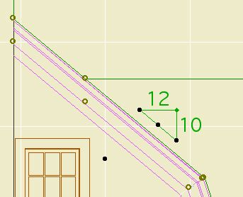
You can stretch the length using the green node.
The hypotenuse is optional for outsiders. In our standards it is on.
See Also: Labels
The label gives the height of a wall. It will typically be used for knee walls. It can be used in section or in plan. It will only work as an associated label; select the wall and check the "Label Elements" box.
The value displayed is the height of the wall in the settings. This means that for trimmed walls, you have to "Set wall height to highest point" when trimming, or manually set the wall height to an appropriate value. Tip: trim the wall using "highest point", then round the height UP to the next 1/4", 1/2", or whole inch.

See Also: Labels
Location - 13 Special Construction
From the Objects We Wouldn't Need If the Tools Worked Right...
The object makes a roof curved around the Z axis. That is, it's not a vault. Here's three of the four that are in use on Vassos.
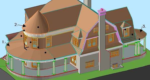
The point is: If you use roof elements, you get a lot of extra lines. With this object you don't. You will still get a line where the object meets a regular roof, but I can't do anything about that. Instead of 16 extra lines, you have two. We do what we can.
The outer radius is controlled by the length parameter. The inner radius, as shown on the porch roof above, is controlled by the "Inner Radius" parameter. If this is zero, you get a point, as shown on the tower.
Naturally you can set the slope and the thickness. Currently the bottom edge is always horizontal; place a slab under it. You can set the three materials separately, as with a conventional roof.
The edge of the roof is detectable in plan, and there are editing hotspots for the arc degrees and the two radii.
The object can show a fill in plan. The fill orients itself to the slope. The fill is a cover fill, so its display will follow the display of the conventional roof fills.
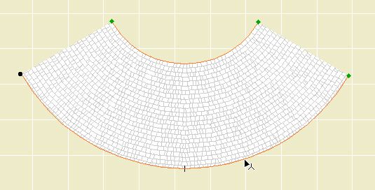
Location: 06 Wood & Plastic : Structure
A 2D symbol for framing in section. It's been around a while, but I added a couple things.
Choose the member type (2x, TJI, LVL) and the spacing. The spacing can be customized.
In building sections (1/4" and 3/16" scales), the label or the joists themselves can be turned off. The label turns itself off when there's not enough room for it. The label can be dragged with in symbol. Turn the joists off when the section cut is parallel to the joists.
In wall sections (3/4" scale and larger), there are some more options. You can show TJIs sideways, which will show the top and bottom flange, along with the rim joist. For cut TJIs, you can choose to show the end joist as a rim joist or not. You can show sheathing on top of the joists. Finally, you can turn on the insulation symbol, so you don't have to draw the insulation separately.
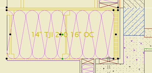
Location: 01 General / 6 Zone Stamps
This is a lot like the JAM8 zone stamp, which was a lot like the room name object.
You can select the room name and the floor finish. The font of the room name comes from the main settings of the stamp. The font of the material has its own setting.
One new feature is the option to show the room number along with, or instead of, the name. The number should generally be shown in the construction documents, in conjunction with the finish schedule. If the number is shown, the floor finish will not be.
The other new feature is the listing parameters for ceiling finish, crown, and baseboard for the finish schedule. These parameters are independent of elements placed in the room.
Location: 05 Metals
This object can take the form of any steel column in the AISC manual. You can set the shape, dimensions and strength. Label it with Description JAM9.
You can choose to model the top bearing plate.
You can display the column dashed below. This is very helpful in developing framing plans: Show the columns overhead to make sure they're all supported.
Location: 03 Concrete
A slab edge, trazezoidal or triangular. Placed under/adjacent to an element of the same fill, it will clean up in section. There was an 8 version of this, but I never wrote it up.
I don't recommend running these everywhere, but a little piece at the section cut helps the section a lot. One less thing to draw.
The goofy thing about this object is I put in a routine where you can edit the section profile in plan. (Turn on "Edit Shape in Plan".) Just an idea.
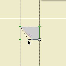
Edit in Plan
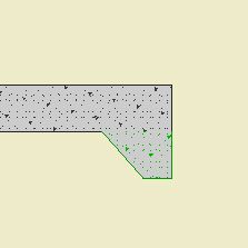
Section
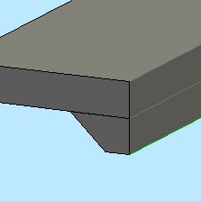
Edit in Plan
These objects have detectable edges.
Cutline JAM9
Cab Blob JAM9
Wood Beam JAM9
Steel W Shape JAM9
Opening Slash JAM9
Stair Arrow JAM9
CenterLine JAM9
All the JAM9 trim objects (Crown, Rake, etc.)
"Labels are text blocks or symbols optionally linked to construction elements and 2D fills. Labels allow you to identify or comment elements or parts of your design." That's from the Archicad 9 Ref Guide page 343, and it's pretty succinct so I'll keep it. Here's more:
"You can use labels in two ways:
• Independent labels manually placed using the Label tool.
• Associative labels can be assigned automatically before the creation of an element or added to them later."
So there's two kinds. Independent labels are like regular objects, in that they do their own thing. There is a simple text label that's basically a text block with a leader, and it works OK as long as you don't go longer than one line. I (used to!) use these to call out structure in the sections and other simple things like that. They are a marginal improvement over plain text with an arc.
Associative labels are attached to elements, and can say intelligent things about them. They remain accurate as the data they represent changes. They can move when the element is moved. They are very cool.
(Why don't we use them yet? Because the underlying design of the label functionality is very poor, making it hard to figure out how they work, especially the differences between the two kinds. Now that I/we have them figured out, the actual making isn't hard.)
Frequently (Probably) Asked Questions follow. I'm focusing on associated labels, since independent labels are simple.
Location: 01 General : 1 Graphic Symbols
A line, with a centerline marker at one or both ends. The line is detectable.
It is superior to a conventional line element since the tags say, "Hey here's a centerline", and an object can be displayed on multiple stories. Same reasoning as the CenterPoint object.
You can use it as a layout element on ! Layout.NP, or you can display it for output by placing it on a note layer. It's sometimes helpful for dimensioning to show centerlines, in which case they should be clearly labeled as such, so here you go.
This object doesn't take the place of the CenterLine Symbol, you still need that to mark dimension ticks. (Did you know? AIA standards say that dimension ticks on centerlines should be drawn as dots rather than slashes. Unfortunately, Archicad doesn't offer this ability.)
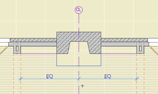
Location: 01 General : 3 Drawing Tools (FYI*)
This is a section tool marker, not a graphic section marker for display in documents. For that, you still use the object SectElevDetail Marker JAM.
It's very simple. The only parameter besides text size is the height of the flag.
Why bother? It's better than the default "basic section" in that it's easier to discern the view direction and the text flips the right way.
You might ask yourself, if we can create section tool markers, why do we still use the object? Because the scripting ability is still limited, and doesn't offer the facility to have the marker differ in shape from the cut.
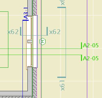
* The location doesn't matter to the user, since you never select the marker from the library. A list of all the loaded section markers appears in the Info Box and Settings Dialog of the section tool. Also true of Details.
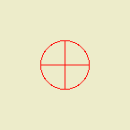
Basically a hotspot. Why not just use a hotspot? Since it's an object, you can show it on all stories, ensuring that the centers stack, and move together.
Also the astronomical symbol for Earth, if you ever need that.
Download (AC9)
NOTE: This is better.
Location: 01 General : 3 Drawing Tools
Two nice changes: There's a 3D version, and the interface for calculating height or quantity is improved.
The defaults for the following parameters the the main title block object have been changed to their respective AutoText tags:
• Project Name
• Type
• Street Address
• City
• State
• Zip
The SK title block uses AutoText tags in the Project Name and Type fields.
That means, new placements of the objects will have these values unless you change them. That means, you need to fill in the book info for the tags to be interpreted correctly (recommended), or edit the settings to display the info the old way. (But why?) Current projects should not be affected, but feel free to set up your book info and use the AutoTexts if you like. If you are going to issue SK sheets, this will make it much easier.
The templates have been updated with the new defaults. The 'Starting a Layout Book' workflow procedure now includes adding the book info.
For new projects, you must set up the book info, or you get this:
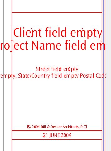
Wow, that makes 'Somebody Residence' look positively elegant.
Location: 01 General/1 Graphic Symbols
An Sheet Size option for 'B 11x17'.
I have updated the templates with an additional detail window to hold the title block at this size. In the layout book templates, I have added a master layout for the 11x17 size.
To use 11x17 sheets in current projects:
Location: 01 General/1 Graphic Symbols/
Description: A mask, frame, and title block for generating SK revision/clarification drawings.
Parameters:
• Sketch Title: Can be entered, or can take the layout name in PM
• Scale: Use Archicad scale, 'no scale', or custom text.
• SK number: May (should) be omitted for automatic generation in PM
• Sheet Reference (optional)
• Project Name
• Issue Date, Past issue dates, and the ability to remember past dates.
Features:
• Interior mask with optional frame, for isolating the drawing part you need. The frame area can be drawn as the object is placed using the Box or Rotated Box methods of the Object tool. The mask can be removed, maxing out the available paper area, by stretching the mask to its maximum size. Note: The masked area will always be centered on the sheet.
• Check the 'Today' box to put today's date in the date fields. If there is a previous issue date, it will be bumped down the list. Or,
• Set the date manually and then check the 'Store Custom Date' box, which also retains the previous dates.
(Note: Both of these checkboxes are designed to uncheck themselves once they have done their work. Don't check them again!)
• The date saving is controlled by the 'Remember Dates' box, and can be turned off.
Use:
• Place in Archicad. Set the SK number to 'Auto in PlotMaker'. Place Hotspots at the corners. Save a view of the sketch area. Import this view into PM, using a layout linked to the 'SK' Master. Print the layout from PM.
• Place in Archicad. Marquee the object, snapping to the corners of the white space. Print, using the 'Marquee Area' option. For this option, you must set the SK number manually. This method is not recommended, since the SK number isn't generated automatically, and the SK isn't saved.
• Scan a hand drawing or other image. Create a layout in PM, using the 'SK Blank + Title' Master.
Place the object and its hotspots on the layer '+Z SK Title'. This layer is hidden and unlocked in all layer combinations. Before placing the object, set the layers/view to one of the output LCs. (E.g., A1) Then either turn on the '+Z SK Title' layer manually, or set the object tool to the layer and click 'show layer' in the 'layer is hidden' dialog box. Save the view with the layers as they are. It isn't a layer combination, but the view won't care. The alternative is to create LCs for every output LC plus the SK Title layer. Too much.
Very Important Note: The object must be brought to front. You might also have to send something back a step to get it hidden. There is no way to automate this. Sorry.
See also:
Sketch Revisions (SKs)
Getting the SK Layout Tools into Current Projects
[Note: This object has been superseded.]
This is the stamp you will use most of the time. Right now it's the only one we have.
It's pretty hard to tell it apart from the Room Name object. There are some differences.
The name list is hooked up to the Room Name parameter of the zone tool, which lets you select from the list in the info box.
The text size of the name is also available in the info box. The size for the material label is only in the settings, though.
There are parameters for the crown type, base type, and ceiling finish, for use in generating a finish schedule. Note: You must enter these. They don't learn from the room automatically, yet.
Location: 04 Masonry
A brick arched wall niche. Duh. Right now it can only do a semicircular arch. It will draw the brick lines on the sides and around the arch. The sill is optional.
In plan, the niche will display correctly. If using the Reflected Ceiling Plan display option, the niche will disappear completely, as if if it was a regular window. Consider using a patch.
Location: 12 Furnishings/Casework
• Obviously, set the number of shelves and the number of vertical divisions. You can also set a maximum height for the shelves and have the quantity calculated. The height of the bottom shelf can be set independently, or not.
• For odd values of horizontal divisions, the width of the center shelves can be set independently.
• There are separate thicknesses for the box, base, shelf, and vertical divider.
• You can choose to start with a shelf or a space (eg, to place on top of a counter).
• For shelves which will be cased like a door, you have the option of using door dimensions for easier alignment.
• All the trim options of a typical door are available, and should behave consistently.
• You can place a 'transom' section on top, which can be divided separately.
• In plan, you can choose a simple rectangle or 'poche' mode, which shows the cut profile of the shelf, including the vertical dividers.
That's all I can think of.
Note: This object is pretty OK, if a bit glitchy, but I'm really enjoying the Cabinet Opening in thick wall method for bookshelves.
All the pocket doors now have a line representing the extent of the void in the wall. Now you know if the door really fits.
Location: 12 Furnishings / Casework
You can miter it, like a trim object. No big deal.
Location: 08a Windows
A window for placing a wall of screen panels at once.
The vertical panels are limited to 3. The rail height and the transom height can be set where these panels are used. These two heights are also graphically editable in 3D, so you can line them up with railings or doors.
You can have any number of horizontal divisions. You can put in the quantity or have it calculated from a maximum width.
Location: 08b Doors
A screen door. Optional screen transom.
Location: 06 Wood & Plastic/Railings & Stairs
Railings and posts in one object. The available settings are the same as 'Rail Level JAM8' and 'Deck Post JAM8'.
The starting and ending posts can be controlled independently of the typical (inside) posts, and of each other, or not. It is possible to build a multi segment rail to allow for posts, and leave the posts themselves out.
Location: 16 Electrical/Elec Symbols.
Replaces 'SwitchMulti JAM8'. Improvements: Bigger 'S'. Any switch can be shown as a dimmer. The extent of the switch plate is shown as a line at the base. This line can be stretched to add or subtract switches. The limit is 6. Probably enough?
It retains the optional 3D. It should be placed on the layer 'E Fixt3' or 'E Fixt2'.
Location: 11 Equipment.
Dishwasher JAM8 is a dishwasher. Fridge UnderCounter JAM8 is an under-counter refrigerator. Pretty simple really.
All the JAM8 windows have a parameter called 'Mode' which allows you to tell the object how to interpret your width and height dimensions. (Then there's schematic mode which draws a glass box. More of a bar stunt than a feature, but it does work.)
The default is for the windows to treat the height and width as the frame size, the outside measurement of the unit. I chose this behavior because it is the most objective overall measurement for a window, when you consider different manufacturers. The other option is 'Jamb', which treats the height and width as the inside dimension of the frame instead of the outside. When measuring an existing window, this is the measurement you'll have.
Both the frame and jamb modes place the window so that the INSIDE of the head is at the head height as given in the settings box, which is the sill added to the height parameter. That is, switching from frame to jamb DOES NOT move the window in Z. The head height in the settings box always reflects the finish head height (above the subfloor, of course).
Reread the preceding paragraph several times.
Window companies are notoriously idiosyncratic about sizes, dimensions, standards, and terminology, to the point that the statement, "I want a 2-8 double-hung" is almost meaningless. Weathershield, for example, refers to its frame size as 'Jamb-to-Jamb', where normal people would think that meant the inside jamb dimension. Not helpful.
You have to develop a knowledge of what the different manufacturers mean by their terms. The only way to do this is to study their details and find the relationships among the various size definitions.
One of my more ambitious goals for the next version of the windows is to teach them the technical differences among the manufacturers, but it might be more trouble than it's worth. In the meantime, as usual, there is no substitute for understanding what you're doing. You might have to put in counterintuitive values to get the windows to behave correctly in a given application. I do it all the time.
BORING!
(Did you know April is national sheet setup month?)
I've modified the drawing area object. Whee! It is simpler, clearer, and just a bit more spacious. It also allows you to disregard the grid in PlotMaker, which allowed me to cut the layout book templates from 5 to 2.
The rectangle is the available drawing area. The ticks on the corners line up with the title block, and set a 3/16" margin around the sheet. Alignment hotspots should be placed on these ticks. The ticks along the edges at each corner are for aligning plan dimensions.
Note: This is superseded in AC10 by Sheet Area RND10.
Note: Superseded in AC10 by this.
Location: 01 General / 3 Drawing Tools
You can't do a detail grid without it. Put in your sheet size. The object knows how big a grid cell is, and how many are on a sheet. Arrow-stretch the object around big details; it will snap to the next size up. At the maximum size it will show the actual grid. This is to place in a master layout to assist drawing the grid in PM.
You must place hotspots at the corners to detect them in PM.
There are guide points for placing the note column, and the note column width can be adjusted. There is an anchor point for the drawing title. The drawing title should extend to the right note margin. Don't adjust the margin or the drawing title elevation unless you have to.
There are detectable points at the midpoint of each side to help with alignment with other details. In addition, there is an editable alignment point with a numeric index of eighths of an inch. Align one detail to a given index, then use that index to align the adjacent ones.
Now that you've fully realized the potential of the current windows and doors, please let me know what you'd like them to do.
This isn't something that will happen overnight; I'm thinking a 6-12 month timeframe, very likely coinciding with Archicad 9. I am only doing the groundwork for the next version, but now is the time to build in big changes. So speak up!
For all JAM8 windows, I have added the ability to extend the masonry sill past the masonry opening. The parameter is called 'Sill Bearing'. The default is zero.
It's about time. I was getting ready to ask what features people want in the next version of the doors and windows (Thinking very far ahead), when I realized there isn't a comprehensive list of the current features, which are extensive. So here.
Location: 09 Finishes
A slate (or whatever) surround with optional moulding. Actually the slate is optional too, you can have just the moulding. You can set the head and jamb widths separately.
PS, right-click on this object in the plan and select 'Go to Info Web Page'. Watch out for recursion!
Location: 01 General : 1 Graphic Symbols.
I have added an option to Opening Slash JAM8 to show an X instead of a single slash, for showing areas open to below. The slash mode is the default.
Location: 06 Wood & Plastic : Structure.
TrusJoist has updated their product line. The TJI model numbers which end in '50' are being phased out. You should stop using them immediately. You should modify the structure plans of any current project not under construction.
I have updated the objects which contain TJI specs with the new model data. The old numbers are still available, but they are moved aside with a reminder to not use them.
I have updated all (I think) the objects for structural beams and such, so that the 3D model can be turned off.
This enables you to put all the beams on the layer S Beam, rather than putting the ones you want to be 2D only on +S Struct Note.
It's neater and more consistent this way.
The effected objects are:
Steel W Shape Beam JAM8
Steel Tube Shape JAM8
Steel Angle JAM8
Wood Beam JAM8
Wood Header JAM8
Hip Valley JAM8
If you run into others that need this treatment let me know.
Location: 05 Metals
A steel pipe column. Pretty simple.
Why use it instead of an actual column? Because columns are evil. Not really. Columns are evil, because they interfere with walls and allow walls to interfere with them. But the reason to use the object is so you can still show the column solid when you set the construction fills' display option to 'Empty'.
Trust me. I'm going to get all this structure plan stuff pulled together real soon.
Location: 06 Wood & Plastic / Trim & Moulding
The shed crown now works better when used as a rake, at the top of a roof. You can turn on the 'Top Skin' to cover the lines at the back of the rake. In doing so it covers the roof itself. Select the skin material accordingly.
The purpose is to improve the appearance in elevation. When creating the roof plan, you should still image the roof itself.
Remember to trim (base) the object to the parent roof, or the top line of the shed will not show.
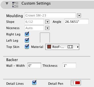
Shed Crown Settings
Location: 01 General : 3 Drawing Tools.
To use in conjunction with grade cutting with SEOs. A U- shaped white stripe which masks the bottom and sides of the mesh in the section. The right end height is the height of the object, and the left-end height is set with an editing hotspot.
Location: 13 Special Construction.
An object for placing a barrel vault ceiling without using roofs.
You can set the radius or the height of the arc, along with the height of the side legs, and the slope of the top surfaces. If the top surface is flat, the side legs will adjust automatically so the arc fits.
Tip: use SEOs to cut the object with the roofs above it, like so:
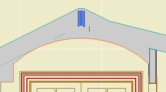
Like so
Like 'Fridge Plain Old JAM8' already can.
Go ahead and replace your titles with Drawing Title JAM81. This object has a new setting, 'Auto Drawing Number'. The default is on. With this setting on, the title in Archicad will appear with 'DRAWINGNUMBER' where the number should be. In PlotMaker, this text will be replaced by a number, which is generated from the position of the drawing in Tree & Subsets view. E.g., If the drawing is listed first, it prints a 1. Move the drawing down in the list, and the number will automatically increase.
This means no more changing numbers in Archicad (Except in weird circumstances; you can turn the setting off and use the ID field as normal).
I have updated the templates with the new object.
UPDATE: More new features.
� Text Sizes: Large, Medium, Small. Presets for text point sizes and expansion. Large is the default, and is the same as the old default. Medium is what I use for wall types and such. Small is really small, I just threw it in. You can also choose 'Custom' and set all the sizes as before.
� Automatic scale in PlotMaker. For typical fraction scales (1/4, 1/8, etc), the scale will come from the frame scale in PM rather than the window scale in Archicad. If you change the frame scale, the title will correct itself. For decimal scales (1"=10.0', etc), the scale is still automatic in Archicad but not in PM: it will not change automatically. (This is because we like the decimal format for these scale, and it can't be set that way.)
� 'Mask': An optional white box behind the entire title, sized automatically. For detail plans, etc. Default: Off
� Automatic minimum length: When the line length is less than the length of the text, the line is automatically extended to the end of the text. The length parameter is represented by a node with a tiny red line, so it's still stretchy.
For calling out wall types and other assemblies. This object is accessed under the detail tool.
Typically you will have the detail drawn before placing this object. In this case, check the 'Link to Detail Drawing' box. (If it's checked by default, uncheck it and check it again. This is the only way to change the reference.) Select the appropriate detail from the list.
The symbol has the tag on the right by default. To flip it, go to settings and check the 'flip' box. Detail markers cannot be mirrored. (?!)
The wall thickness can be set in the settings or graphically edited. The wall should be contained between the two triangles. The tail end and the tag end of the marker are also stretchable with the arrow tool.
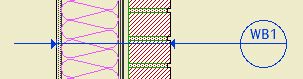
The subject
The unique ID of the detail will display in the top half of the tag. (Use the same info for the 'number' in the drawing title object within the detail.) In Archicad, the bottom half is blank. If 'Auto Sheet Number in PM' is checked in the settings, the sheet number of the drawing will be displayed in PlotMaker automatically.
Location: 08b Windows.
The Benton/Van Dusen juggernaut has rolled over my puny defenses and forced the manufacture of Garage Door Arch JAM8, French Casement JAM8, and < strong >Ext Fr Dbl ArchTran JAM8, which, pardon the shorthand, is a double french door with an arched transom.
The moral of the story: If you need something, ask!
But that's not all. I can also offer Arch Window JAM8b1, located at 2 Project LIB : Stevens. The 'b1' means beta. Which means it's not perfect. You're welcome to it, but there's definitely room for improvement. At least the interface and features are consistent with the other windows.
Location: 2 Project LIB : Stevens.
An arched cased opening.
If the wall is thick enough, you can opt for panels on the jambs. I have also added this functionality to the regular Cased Opening JAM8.
Location: 06 Wood & Plastic : Columns & Pilasters.
Tuscan Column JAM8 replaces < strong >Column Classic from the Smart Parts library, and < strong >Column Classic SP8, derived therefrom.
This column is a lot better.
Location: < strong >13 Special Construction.
This is so cool.
Using Solid Elements Operations and this object, you can cleanly slope the top of a curving wall. Handy for landscaping.
Location: 04 Masonry / 2D Masonry.
Shows bricks and mortar joints for large scale section details. The fills and dimensions are parametric, and it can be stretched to any length and it will end properly in the middle of a brick or joint.
I am working on a lot of brick-related stuff for the Stevens project, including more detail objects and standard details. Stay tuned.
I have updated the object Title Block JAM8. You can choose to have the print date automatically set itself to the current day. Check the 'Today' checkbox, and the year, month, and day fields will update. The checkbox will then uncheck itself; this is intentional. If the checkbox were left on, the date would change every time you opened the settings, which, no.
I have updated the version 8 doors and windows with an option to build a masonry jamb.
I have updated the object Gutter JAM8. Again. There is now a gutterboard option, with thickness, height, and vertical offset.
This is a howto for a simple bracket object made from a slab. This technique is sometimes called 'slabify'. Keep in mind that anything you can make in Archicad can be saved as an object.
Location: 15 Mech-Plumbing.
A 2D symbol for HVAC supply, return, or exhaust fan. There is an optional label for the size, generated automatically from the height and width. The height and width snap to whole inches.
I have updated the object Elev Marker JAM8. You can automatically display the elevation to Sea Level, as well as Project Zero. There is also an option for a break point when the symbol needs to bend.
In order to use Sea Level, select it in the Reference Level parameter. You must have your '1st Reference Level' set properly in Options -> Preferences -> Working Units and Levels.
To show a bend in the symbol, set the Break Point parameter to greater than 0. The height of the bend comes from the Height parameter. When Break Point=0, the Height is ignored.
I have updated the object Gutter JAM8. You can display the position of the downspouts on any/all of the three stories below, at heights you specify.
The primary purpose of this is to show slab penetrations.