Location: 06 Wood and Plastic / Railings & Stairs
Here's a new railing object. It should be the only (simple) one you need, since it can be interior or exterior, and level or sloped.

Location: 06 Wood and Plastic / Railings & Stairs
Here's a new railing object. It should be the only (simple) one you need, since it can be interior or exterior, and level or sloped.
Location: 04 Masonry : Chimney & Fireplace
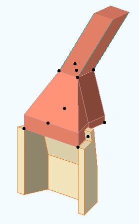
The missing link between Firebox JM9 and Flue JM9. You could use a mesh and a slab in its place, but why?
The smoke chamber fits on top of the firebox. The width, depth, and firebox Back width should match the Firebox Lining object. The flue width and depth should match the Flue object. The front of the flue lines up with the back of the firebox. You can't change this.
The throat height is the distance from the top of the firebox to the start of the smoke chamber slope. The shelf depth is the distance from the slope start point down to the bottom of the smoke shelf, behind the firebox. The throat adjustment is for hiding the edge of the smoke shelf inside the top of the Firebox Lining. (Very easy to see in section image below the fold.)
The object should be placed on the layer A Flue. Model it with a visible, white-printing pen such as 40. For the material, use the material you want to see inside the flue. The Flue Pen should be a printing pen, to show the start of the flue above.
More images below the fold.
Location: 04 Masonry : Chimney & Fireplace
Just the fire brick part. Looks good in plan, section, and elevation. For a correct section, align the polygon wall of the firebox core with the inside of the Lining object, then subtract the object from the wall.
Images below the fold.
Location: 04 Masonry / Chimney & Fireplace
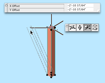
A round or rectangular tube for modeling chimney flues. The top can be offset for a sloping flue.
Plan Display & Editing
"Show Cut" means a white box with a X. "Show Slant" means the path of the sloping flue, typically shown dashed. Both can turned off, in which case the object will be invisible, but the nodes will remain. The cut polygon can represent the top or bottom. The flue size is stretchable by any corner. The top offset can set by stretching the green node.
3D Editing
The offsets and the height can be edited with the green node in 3D.
General use
The idea is to build the flues out individual segments using the object. Use the layer A Flue. Subtract the flue objects from everything they pass through. When subtracting, use "Inherit attributes of operator".
The layer A Flue should generally be set to wireframe.
I had a thickness parameter in there, to show the flue material itself at large scales, but I had to take it out because of incompatibility with the smoke chamber object.
UPDATE 3-16-05: Round option. Duh.
Location: 01 General : 3 Drawing Tools
Very simple, just two (presumably) vertical lines. It has but one setting, the width of the column on paper. Saves you the hassle of multiplying by the scale to figure out how to space the lines yourself. The lines are detectable; wouldn't be very useful otherwise.
Since we got a new plotter, we need a new title block. Makes sense to me.
Before printing from the new plotter, you must switch to this title block object. When switching, hold down command and option and click on the new object. This is very important so you don't lose your old issue dates. If you try switching and it doesn't work, cancel out of the object settings and try again.
The object looks the same, but I took the opportunity to fix/add a couple things.
The overall size of the object, including the margins, is the same as the paper in the layout. In the previous version, the size matched the printable area. When changing an existing project, make sure the lower left corner of the title block drawing is on the lower left corner of the paper. (The outermost rectangle, if you can see a difference, which for large sheets you won't.)
You can have up to eight dates instead of five. You can limit the number date spaces to four.
If the client name doesn't fit the title block horizontally, you can make the point size smaller (Custom Project Size), or put part of the name on a second line (More Project Name). Note: This parameter is separate from the Book Info. You can still use the Book Info for the other fields. That is, if you want the second line, you have to set it in Archicad.
I turned all the pens black, and lightened the gray on the square a little.
Location: 01 General / 1 Graphic Symbols
Just like Slope Symbol JAM8, except it's a label. Used as associated label on a roof, it will convert the slope to n/12 and draw the triangle correctly. This symbol is typically used in section and elevation, but I could see using it in the roof plan.
Select the roof you want to label and check 'Label Elements' in the Info Box.
(To set the label tool to use this label on roofs, go to the default settings of the label tool, highlight Roof Tool in the top panel, and select Roof Slope JAM9 from the flyout.)
After activating the label, you will have to move it into position. Make sure "Use Symbol Arrow" is checked in the Info Box. This keeps the leader from being drawn.
To label a roof which slopes in the other direction, switch the "Mirror" parameter to On. Conventional mirroring doesn't work.
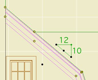
You can stretch the length using the green node.
The hypotenuse is optional for outsiders. In our standards it is on.
See Also: Labels
The label gives the height of a wall. It will typically be used for knee walls. It can be used in section or in plan. It will only work as an associated label; select the wall and check the "Label Elements" box.
The value displayed is the height of the wall in the settings. This means that for trimmed walls, you have to "Set wall height to highest point" when trimming, or manually set the wall height to an appropriate value. Tip: trim the wall using "highest point", then round the height UP to the next 1/4", 1/2", or whole inch.

See Also: Labels
Location - 13 Special Construction
From the Objects We Wouldn't Need If the Tools Worked Right...
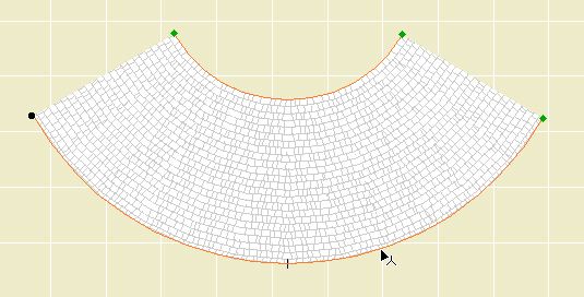
The object makes a roof curved around the Z axis. That is, it's not a vault. Here's three of the four that are in use on Vassos.
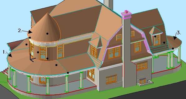
The point is: If you use roof elements, you get a lot of extra lines. With this object you don't. You will still get a line where the object meets a regular roof, but I can't do anything about that. Instead of 16 extra lines, you have two. We do what we can.
The outer radius is controlled by the length parameter. The inner radius, as shown on the porch roof above, is controlled by the "Inner Radius" parameter. If this is zero, you get a point, as shown on the tower.
Naturally you can set the slope and the thickness. Currently the bottom edge is always horizontal; place a slab under it. You can set the three materials separately, as with a conventional roof.
The edge of the roof is detectable in plan, and there are editing hotspots for the arc degrees and the two radii.
The object can show a fill in plan. The fill orients itself to the slope. The fill is a cover fill, so its display will follow the display of the conventional roof fills.
Location: 06 Wood & Plastic : Structure
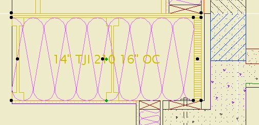
A 2D symbol for framing in section. It's been around a while, but I added a couple things.
Choose the member type (2x, TJI, LVL) and the spacing. The spacing can be customized.
In building sections (1/4" and 3/16" scales), the label or the joists themselves can be turned off. The label turns itself off when there's not enough room for it. The label can be dragged with in symbol. Turn the joists off when the section cut is parallel to the joists.
In wall sections (3/4" scale and larger), there are some more options. You can show TJIs sideways, which will show the top and bottom flange, along with the rim joist. For cut TJIs, you can choose to show the end joist as a rim joist or not. You can show sheathing on top of the joists. Finally, you can turn on the insulation symbol, so you don't have to draw the insulation separately.
Location: 01 General / 6 Zone Stamps
This is a lot like the JAM8 zone stamp, which was a lot like the room name object.
You can select the room name and the floor finish. The font of the room name comes from the main settings of the stamp. The font of the material has its own setting.
One new feature is the option to show the room number along with, or instead of, the name. The number should generally be shown in the construction documents, in conjunction with the finish schedule. If the number is shown, the floor finish will not be.
The other new feature is the listing parameters for ceiling finish, crown, and baseboard for the finish schedule. These parameters are independent of elements placed in the room.
Location: 05 Metals
This object can take the form of any steel column in the AISC manual. You can set the shape, dimensions and strength. Label it with Description JAM9.
You can choose to model the top bearing plate.
You can display the column dashed below. This is very helpful in developing framing plans: Show the columns overhead to make sure they're all supported.
« Newer | All Entries | 1 | 2 | 3 | 4 | 5 | 6 | 7 | 8 | 9 | 10 | 11 | 12 | 13 | 14 | 15 | 16 | Older »