On Land

Environment Information
At Rill Architects we run ArchiCAD on macOS. If you work at Rill, this is your stuff. If you don't, but you work in ArchiCAD, you may find something interesting. Anybody else, I don't know.
RSS
Objects Archive

« Newer | All Entries | 1 | 2 | 3 | 4 | 5 | 6 | 7 | 8 | 9 | 10 | 11 | 12 | 13 | 14 | 15 | 16 | Older »

To these you can add:

Align Symbol JAM8
Drawing Title RND9
Elev Marker JM9
Joist Note JAM9
Note Column JAM9
Footing Stepped JM9
Stud Wall Detail JM9
Gutter JAM8
Insulation Batt MTL8
Rod+Shelf JM9
Railing JM9
All the wood and steel beams
Anything made from the Miter Object Template JAM9

If you see an object that should have detectable edges and doesn't, let me know.

Obsolete in AC10.

Location: 01 General : 1 Graphic Symbols

An incremental improvement to Elev Marker JAM8, which it replaces. The 'bending' is now handled by editing hotspots.


First spot: beginning of bend. Second spot: End and depth of bend. End spot: depth of bend and length of object.

Somewhere along the line I added the ability to display the elevation relative to sea level as well as project zero, without telling anyone, so now I've told you.

Location: 06 Wood & Plastic : 2D Wood

This object makes it easier to fill in stud walls in wall sections. It combines plates, headers, blocking, drywall, sheathing, and insulation, in any combination, for 2x4 or 2x6 walls.

At the top you can have a plate, double plate, or nothing. The bottom has these options plus a header, and an optional anchor bolt for the plate.

You can show batt insulation or not, and show mid-height blocking or not.

Outside the studs on either side you can have a fill for drywall, plywood, or neither. The perimeter line on both sides is optional. If you are placing the object in an existing wall, you usually don't need these lines.

This object is another aid to developing wall sections while keeping them model views. If there's anything it could do that isn't, let me know.


UPDATE 12-22-06: Added the ability to extend the side fill along the ceiling on either side, even at an angle.


The spot at the end stretches the length, and the spot in the middle adjusts the angle.

A label to show the elevation of the top or bottom of a slab.

It works in plan or in section, and changes its form depending on which kind of window it's in. It can give the elevation to project zero or the home story of the slab.

I made it in an attempt to overcome one of the big limitations of the Level Dimension tool: It can't read the bottom of an element. If you can read the bottom of an element, you can show live ceiling height dimensions in the RCP. I'm also attempting to overcome one of the big limitations of the level version of the regular dimension tool in section: It isn't truly associative and doesn't move when the slab does.

In creating this label, I discovered and did mortal combat with several disabilities in Archicad, and especially in the label functionality. In the end, it doesn't do nearly what I want it to, but it's (mostly) not my fault. The section version works well for showing ceiling heights, as long as the slab is on the same story as the room. To use the plan version in RCP, my original primary goal, involves additional layers, or commits me to fussier modeling of ceilings than is otherwise needed, and is tedious to maintain.

(I wrote a mini-white-paper mapping the related Archicad disabilities on Archicad Talk, if you're interested, here it is.)

So even though the plan version has three broken legs, the section version is passable, so here it is.

Use it as an associated label, of course. Choose to label the top or bottom, to project zero or the home story zero.

In plan, you should only use it to label the bottom of a slab; for the top, the level dim is far superior, since it can read hidden elements.

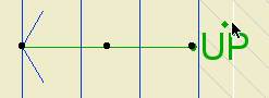
The plan text can moved anywhere, and will flip around depending on what quadrant it's in. Sorry about the separate X & Y editing hotspots, for some reason they can't coincide in labels. I regrouped and got it working; the current version is for AC10 or above.

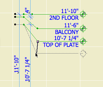
When placing the label in section, it will always appear at the lower left corner of the slab. If you are dimensioning the top, you need to move the label manually.

Download (AC10)

Location: 01 General : 1 Graphic Symbols

Very similar to SectElevDetail Marker JAM9, with the improved autotext handling discussed here.

Same as with Detail Area JAM9, paste just the gibberish part of the autotext from PlotMaker into the "Paste Autotext Here" field. The drawing name and number will fill in. If you are using the Double Section symbol type, paste the data from the other drawing into the "Paste Autotext 2 Here" field. If the drawings are on the same sheet, as they usually will be for a pair of sections, leave "Same Sheet Number" on. If you turn this off, the second sheet number will be generated from the second pasted text.

Once I put up that screenshot of the detail marker, I noticed that the gibberish components of the two autotexts are the same. The difference lies in the DRAWINGNUMBER_R and LAYOUTNUMBER_R tags at the front.

This means I can have reference markers (section and detail flags) that just need to be told the gibberish segment once, and can build the autotexts themselves. For these objects, instead of copying the entire autotext in PlotMaker, just copy the data within the second pair of angle brackets: "<9BEA5D4E-8700-11D8-8AA9-000A95A7B33A>".

I have added this ability to Detail Area JAM9. In the settings, paste the gibberish into the "Paste Autotext Here" field. In the drawing and layout number fields above, you will see the completed autotext fill in. You can still put non-auto text in these fields; if you delete the "Pasted" data, the fields will empty and unlock, and you can use them however you want.

For labeling doors and windows in section/elevation. This is completely different from the dimension marker used in plan.

It is intended to be used as an associated label.

How about a quick review of associated labels. To place an associated label, select the element, in the window you want the label, and Check 'label Elements' in the Info Box. Which label will be placed? Ah. Each tool has default label settings, which are configured in the Label settings dialog. For each tool you want to label, highlight it in the list at the top and choose the appropriate label from the top right flyout. This is also where you set the pen, layer, and other attributes of the label. Remember that labels can have a different layer than the elements they reference, and they usually will.

For doors and windows, starting today, set the label tool to use Door-Window Label JM9.

It draws a hexagon for windows and an ellipse for doors. It knows the difference! If Auto Size is on, the window tag will be 5/16" and the door tag will be 3/8". If these don't meet you needs, turn Auto Size off.

Once the label is placed, move it where you want it. (A method to control where labels pop up remains elusive.) Place the label on a sash with no divisions, or to the side of the window/door. Try not to obscure the design of the window/door.

See also:
Labels

Location: 06 Wood & Plastic / Structure

An object for modeling and annotating wood structure elements.

More»

Location: 03 Concrete

The main parameters are the height, width, and thickness.

By default, the overlap matches the thickness, and the tread is double the thickness. To change either value, set the parameters to other than zero.

The length of the object cannot be controlled. The idea is to let the object tell how much length is needed to step up the required height. The resulting length is the distance between the adjacent slabs. The length is shown, locked, in the length field.

The object "starts" at the bottom. When the length changes, the top end moves.

The top of the object will match the top elevation of the upper slab footing. The bottom, it depends:

If meeting the lower footing "in line", the bottom elevation should match the top of the lower slab, and the "Bottom Lap Segment" should be on. If meeting the lower slab at a "T", the bottom of the object should match the bottom of the slab, and the lap segment should be off. I think the second case is more typical, and is shown in the image below.

The "length" rectangle is shown with the floor plan pen of the object. The adjacent slabs should meet the ends of this rectangle. The red line indicates the bottom of the object, and the extent of the Bottom Lap Segment, if on. The light pink line shows the physical extent of the object at the top. Both these lines print white. The lines in between represent the elevation changes (steps).


In plan.

Placement: The object should be drawn with a dashed line. I suggest using a different pen from your footing slabs, with the same weight. Use the layer S Footing. Set the bottom elevation first, as described above. Next, set the top elevation. The object will extend to accommodate the needed "treads". Then adjust the upper slab to meet top end of the object. (This end is represented by two small lines instead of a full line, so it doesn't interfere with the end line of the slab.) Whenever you change any parameter of the object, you will need to adjust the top slab too.

Cutting the foundation wall: The wall which sits atop the object should extend to the edge of the top slab. The wall's base should be at the top of the lower footing. Subtract the object from the wall with downward extrusion. Without SEOs, this object wouldn't be possible.


Cutting the wall.

Location: 13 Special Construction

When using a thin wall for casing or paneling, a window for cutting the outside of an arch casing. You can set the height and the width. You can choose to extend the hole on either side of the arch to cut more wall.

Like the Openings in the Archicad library, you can preview the shape of the window in the settings box elevation view.

Here's what it's for. I used an Archicad library arch opening for the inside.


Location: 06 Wood & Plastic : Railings & Stairs

This is essentially the same as Newel STUM8. It has a cap and a plinth. The only thing I added is the ability to have a different pen when shown one story up, so it can match the behavior of Railing JM9. I figured you wouldn't show it on the story below very often.

Location: 01 General : 1 Graphic Symbols

I actually updated this about 3 months ago. The only differences from the previous version are the addition of the Z shape option, and the ability to flip the direction in plan, using the hotspot above (UP) or below (DN) the direction text.


« Newer | All Entries | 1 | 2 | 3 | 4 | 5 | 6 | 7 | 8 | 9 | 10 | 11 | 12 | 13 | 14 | 15 | 16 | Older »