On Land

Environment Information
At Rill Architects we run ArchiCAD on macOS. If you work at Rill, this is your stuff. If you don't, but you work in ArchiCAD, you may find something interesting. Anybody else, I don't know.
RSS
Objects Archive

« Newer | All Entries | 1 | 2 | 3 | 4 | 5 | 6 | 7 | 8 | 9 | 10 | 11 | 12 | 13 | 14 | 15 | 16 | Older »

Location: 08b Windows

A simple screen panel for a screened porch. Not a screen for a window unit.

Frame Width and Thickness: Dimensions of the border trim. There are two frames, one inside and one outside, with the screen in the middle.

Balusters are optional; set the Width and Spacing. The balusters are built within the inside frame. They can have their own pen, which should be thin.

Frame and Screen Material: Obvious.

3D Cut Pen: A window hole is usually outlined with the wall's 3D pen. This parameter lets you use a different pen for the hole.

X
X in Section: Draws an 'X' inside the frames at scales greater than 3/4".

Location: 06 Wood & Plastic / Shutters

Note: Though the name says 9, it needs 10.

Very basic window shutter(s), perfect for existing conditions.

Single or Pair: If it's a pair, the shutters will be spaced using the object's length setting. This way you can stretch the opening to fit a window.

If it's a pair, you can Fit Pair To Opening, which sets the shutters' width to half of the opening dimension. If Fit is off, or if it's a single shutter, Shutter Width controls the width.

The basic dimensions of the shutter are Frame Thickness, Frame Width, and Panel Thickness.

Panel Type can be Flat, Raised, or Louvers. If it's Raised, you can set the Width of the border and Thickness of the raised part. For louvers, use a fine weight for the Louver Pen.

We don't have infinite panel arrangement options; it's a basic shutter. You can have one or two panels. You can have Equal Panel Heights, or a Square Panel at the top or bottom, or you can set the Bottom Panel Height manually.

Location: 13 Special Construction

A big dull block for subtracting a rectangular hole into a ceiling slab. Why not use a slab for an operator? Why not just draw a conventional hole in the slab? Because while the 3D block is dull, the plan symbol is rather clever, responding intelligently to the new ceiling switch in Model View Options.

Dashed in Plan

To review what the ceiling switch is all about, check the Ceiling Line JM11 post. Like that line object, the soffit cutter has separate attribute settings for plan and RCP. Either set of attributes can match the objects settings, while the other can differ. I like to treat the plan as primary and the RCP as the variation, so I have the object's linetype set to 'Dense Dashed'. In the parameter list, the Plan Linetype is 0 (matches the object settings), and the RCP Linetype is Solid Line. You can also change the pen, but I don't see the need.

RCP fill editing
There are also settings for an optional RCP Fill, with the typical Fill and Pen settings. If you turn on the Fill Origin, you get two editing nodes for moving the fill origin and rotating the pattern, like a regular fill. No handle, just pay attention.

The cutting takes place with solid element operations, with the main ceiling as target and this object as operator.

Such an object has peculiar display requirements so the layer is very important. It shows in plan, RCP, and working model/section/elevation (so you can work with it), but is hidden in output sections (where you want to see the effect of the operation but not the operator itself). So in the templates we have a new layer, X Ceiling Cut. Like most cutting layers, it's wireframe. You would need to create this layer in running projects and show/hide/wireframe it as described.

Of course, sadly, for a non-rectangular hole you still need to use a slab, and you still need to trace.

Original here.

You can have a Second Crown above the first one. The Nudge parameter controls the overlap of the two crowns in section. And, a Cap, which is just a block like the base. (Turn all the mouldings off and you have a simple post.) And, a Bead moulding between the panels and the top crown.

Location: 03 Concrete

A 3D concrete beam with rebars, and/or a 2D symbol of a concrete beam section.

Placed in...

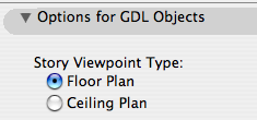
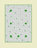
Model means a 3D beam that will show up in plan and section. Note that the actual placement will very likely take place in the plan window.

2D Detail means a 2D symbol of the section through the beam, suitable for placement in a detail or wall section window. This mode has no 3D part.

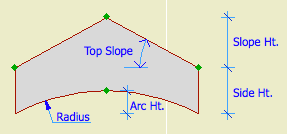
Depth is the Z dimension.

Top Width allows you to make the top wider for slab-thickening applications. Zero means keep it rectangular.

Rebar Size: Choose a number.

Model Beam Section
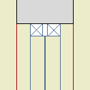
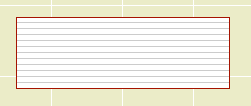
Section through Model beam
Put in the number of Top Bars and Bottom Bars. Zero is OK for either one. Bar Coverage refers to the minimum dimension between the bars and the outside. Within the coverage, bars are evenly spaced. Mid-Height Bars puts a bar at the midpoint on the right and left.

Note that the bars are not modeled at scales smaller than 3/4". They will be visible in wall sections, but not building sections.

2D Detail
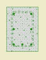
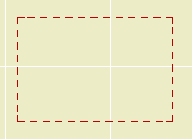
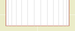
2D Detail mode with stirrups
Stirrup Size: Choose a number. Zero means no stirrups. Be advised that the stirrups are not modeled in any case. They will be shown dashed in the 2D Detail mode, and called out in the label of the plan symbol.

Concrete controls the display of the 3D beam itself in Model mode, and the fill pattern in 2D Detail mode. This effectively gives the option of 'bars only' for cases where the concrete is already represented by another element, such as a 'real' beam.

Beam Outline: 2D Detail mode only. Controls the display of the rectangle, independent of the fill.
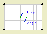
Model Beam Section
In Plan
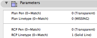
Plan Symbol: Model mode only. 'Rectangle' draws the top view of the beam. 'Single Line' draws one broken line. 'Multi-Line' draws one broken line for each bottom bar.

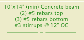
The Label is for calling out the beam in framing plans. By default the label describes the width, depth, rebars, and stirrups. Label Bars Only turns off the dimension part. (min) adds that text after the beam's height dimension. Stirrup Spacing only applies to the label; remember the stirrups are not modeled.

I think the label is pretty intelligent about describing the beam's composition in most cases, but if you push past its limits you can turn on the Custom Label and write whatever you want on the three lines.

ID Tag is the typical circle for referring to the beam's structural calculations.

Tips:

• For a simple opening in a concrete wall, use Model mode, turn the Concrete off, and set the label to Bars Only.

• Modeling the beam is usually preferable. The only thing the modeled beam can't do in section is show the stirrups. You can add a section symbol for the stirrups by using 2D Detail mode, Concrete off, Stirrups on, zero rebars.

Location: 08a Doors

The interior door.

More»

Location: 13 Special Construction

For modeling a vaulted ceiling under a flat ceiling or a gable roof.

Barrel ceiling section
Heights are editable in 3D and section.

Turn on the Ellipse parameter for an elliptical curve. Other wise it's a simple arc.

With the Model View Options in 'ceiling mode', the object can use the optional ceiling pen, linetype, and cover fill. (Use the layer F Trim Crown, which shows in RCP and section/elevation combinations.)

Barrel ceiling in RCP

The Arc Lines option will draw lines with variable spacing to illustrate the curve:

Barrel ceiling arc lines

You can use the arc lines as a 2D-only symbol by turning the Model parameter off.

Download (Requires Slope macro)

Electrigon is a free set of symbols for electrical fixtures with the ability to calculate electrical requirements for a project. The new version brings some more geometry options and improved calculations.

Yes, such functionality should ship with Archicad. We do what we can.

Ceiling Switch
In Model View Options
Location: 01 General / 2 Drawing Tools

Among the least heralded new features of Archicad 11, tucked into the bottom of the Model View Options dialog, is the modestly named 'Story Viewpoint Type'. Not heralded at all, in fact; there's no mention of it in the New Features Guide. I understand why they don't want to call it out too loudly. Its impact is rather narrow, and the Archicad library itself makes very limited use of the feature.

Right, what is it. It's the long-awaited (by me) environment switch to put the floor plan window in 'Ceiling Plan' mode. Wouldn't it be nice if things could draw themselves dashed in plan and solid in RCP or vice-versa. Less tracing, less maintenance, more unity. This is a pet issue of mine, so I'm happy to see it, even in its narrow, modest, unheralded current state. I'm calling it the 'ceiling switch' because no one knows what 'Story Viewpoint Type' means.

The switch gives the opportunity to have objects draw themselves one way in plan and another way in RCP. But: Only objects, which includes doors, windows, and lamps. It does not apply to regular modeling elements such as slabs and beams. Keep hope alive.

I've made several objects which take advantage this tech, and I plan to retrofit more as we go.

Ceiling Line JM11

The first one is, a line! Haha! I know, if things are more unified you should draw... less! It's ironic. But there's more to come and this serves to illustrate the basic idea.

Ceiling Line parameters
There are four parameters; a pen and linetype for plan, and a pen and linetype for RCP. Any of the parameters can be set to "0", which means the line will be drawn using the object's settings (the pen and linetype shown in the Info Box). You would either have the plan use the object settings and customize the RCP, or the other way around. (Don't pay attention to all that 'Missing' and 'Transparent' stuff. It's just how AC interprets the zeroes.)

Linetype tile
Using the default settings as an example, the object is set to use the 'Dense Dashed linetype, and the Plan Linetype is set to "0", so the line will be drawn with 'Dense Dashed' in plan. The RCP Linetype is set to 1 (Solid Line), so in ceiling mode it's drawn solid.

You could do the reverse: Let the RCP use the object settings and customize the plan parameters. Either way.

What's it for? Roof overhangs. You have to draw them anyway, because showing the roofs themselves is a mess. Use this object instead of a line, and get the overhangs in plan and RCP simultaneously. And: Miscellaneous ceiling lines such as those in an attic.

Template Changes

We need a new layer, which is A Ceiling All. This layer shows in plan, RCP, and all the model combinations.

To handle the ceiling switch itself, we need a new Model View Option combination, which is A4 RCP. In previous versions, the RCP used A4/S0/M/P; now that one's just S0/M/P. When migrating a project, you'll need to create this model view combination and assign it to the RCP views.

Location: 04 Masonry / Chimney & Fireplace

It's very hard to describe this object independent of the whole chimney process, but I'm going to try. Once this guy is written up we can look at how it, the firebox, and the flue work together.

This version is superior to the JM9 version in that the flue is better oriented with the firebox. In other words, it's less wrong.

The smoke chamber object makes a void. It is intended as an SEO operator. Like the flue, it's supposed to drill a hole through the chimney material.

Smoke Chamber plan
Parameters in plan
The Length matches the width of the firebox opening. The Width matches the firebox depth. Firebox Back Width matches the back width of the firebox. The back width is editable in plan.

The object is wider than its Width by the value in the Firebox Wall Thk parameter.

So that's four parameters that the smoke chamber takes from the firebox.

Likewise, Flue Width and Flue Depth should correspond to whatever you're using for the flue.

Smoke Chamber section
Parameters in section
Height is simply the overall height. The bottom elevation of the smoke chamber should match the top of the firebox.

Throat Height is the dimension of the plumb portion of the front of the object. Damper Height is the height of the sloped portion, which straightens out again at the flue depth.

Shelf Depth is measured down from the Throat Height. It carves out the place where you have to draw in the curved bit of mortar.

Throat Adjustment doesn't make sense until you see how the smoke chamber and firebox subtract from the chimney material. It's there to keep that vertical edge with the firebox wall, so there's no excess wall stuff hanging down.


Place the object on the layer A Flue. Use a non-printing pen (60 is good), and the material you want to see on the inside of the subtracted space (Brick Surface Color is good).

A Flue shows in plan, so the non-print pen hides the object in output. It also hides the weird lines on the surface of the object in section, which would be visible in the targeted chimney material. You can choose to show the smoke chamber's "flue X" by turning on Show Flue.

Location: 01 General / 1 Graphic Symbols

UPDATE 2019-11-12: Replaced the solid fill called by name with the global variable for the first solid fill in the fill list. (This might be 100%, 'Solid Fill', 'Foreground Fill', etc.) Now the mask fill won't fail if the 'Solid Fill' isn't available. This version is for Archicad 22.

UPDATE: Backsaved version for AC9.

Same features as the AC9 version, with a simplified interaction for getting the loop off center.

Cutline JM10

More»

Location: 06 Wood & Plastic/Trim & Moulding

New version of the main moulding object.

Listen, you will have dozens or hundreds of Crown Tool elements in a project. The object is designed to be used all the time. I.e., it does a lot. Get familiar with what it can do. If it doesn't do something you need, speak up!

This version: There are additional 'shapes' and more parts available. New shapes:

• "J"; like "U" with an independent length for the third segment.

• Rakes, including curved rakes.

• Arch.

New parts:

• Wall Backer 2. Placed behind the Wall Backer.

• Crown Cap. Placed below the crown.

• Soffit. Flat piece placed above the ceiling backer. You will often need this to help the rakes cut the roof edges.

I regret to inform you that I can't continue support the custom interface panel at this time, so we're stuck with the parameter list. Essentially, all this stuff is hard enough to simply get working, and the user interface development tech is painfully disrespectful to time constraints. I have to choose between features and interface and it isn't a hard choice. If this makes you unhappy reread the new features list above and cheer up!

Full documentation below the fold.

More»

« Newer | All Entries | 1 | 2 | 3 | 4 | 5 | 6 | 7 | 8 | 9 | 10 | 11 | 12 | 13 | 14 | 15 | 16 | Older »