Location: 06 Wood & Plastic/Columns & Pilasters
A decorative column or pilaster, with an optional panel, and mouldings for the top, base, and panel.

Location: 06 Wood & Plastic/Columns & Pilasters
A decorative column or pilaster, with an optional panel, and mouldings for the top, base, and panel.
Location: 06 Wood & Plastic/Brackets
A bracket that looks like this:
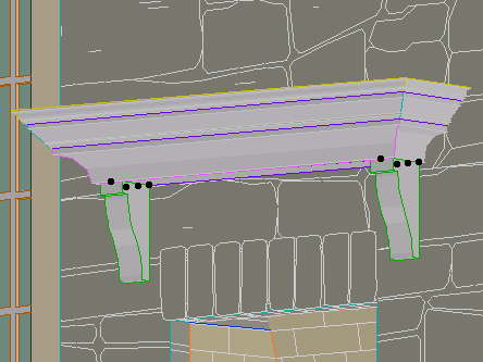
You can set the width (X), thickness (Y), height, height and depth of the nose, and width of the base. That's about it.
(By the way, the arch is slabified.)
Location: 06 Wood & Plastic
One, or many, rafter tails or pergola elements. A huge improvement over Rafter Tails HOOV8.
Location: 01 General / 1 Graphic Symbols

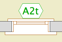
This one has square, rectangle, triangle, circle, ellipse, oval, diamond, and hexagon.
The rectangle, oval, and hexagon will elongate to accommodate the text, if the Stretch for Text parameter is on. The square will turn into a rectangle.
The Height parameter refers to the vertical dimension. The Length Factor parameter is multiplied by the height to get the length of the rectangle, ellipse, and oval shapes. If Stretch for Text is on, the length is overridden by the text length.
The text, by default, is the global ID of the object. You can also choose to enter a custom text.
The size of the text can be set by points, millimeters, or as a fraction of the shape height. All these parameters are hooked together, so when you switch among them the actual height stays the same.
There is a value list for the font, and you can enter any font name. The text can be shown bold, italic, underlined, or any combination.
Update 2007-12-13: The Mask parameter will make the shape opaque white, using the 'Solid' Fill and White Pen parameters.
I'm making this object available for download on Archicad-Talk. (Hence the mm size option.)
Or download here.
Location: 06 Wood & Plastic/Trim & Moulding
This has been deployed for some time, but here's the 'documentation'. It may or may not tell you something you don't know. I have also fixed a couple of minor glitches and finished the custom interface page, finally.
Location: Doesn't matter; window & door markers are selected from the flyout in the info box or the 'dimension marker' tab of the settings dialog.
WindowTag: When the ID doesn't fit in the regular hexagon, the shape elongates to accommodate it.
DoorTag: I fixed that upside-down text thing, I'm pretty sure. I took out the Flip Text parameter. If it gives you any trouble let me know.
Update. The AC11 versions have RCP-awareness.
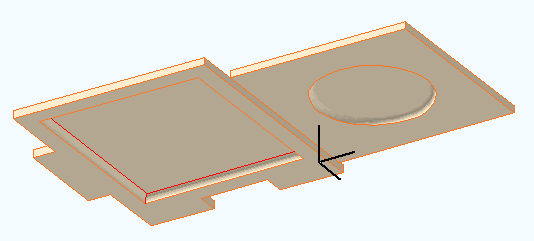
Location: 13 Special Construction
Two objects (primarily) for cutting coved recesses into ceilings, using solid element operations. One's a circle, one's a rectangle. Guess which is which. The parameters of each are similar.
The fillet radius must be less than or equal to the height. The resolution of the fillet is controlled by the Fillet Facets parameter. For the disc, the Resol parameter controls the resolution of the circle.
You can turn the objects upside-down with Flip Z. I can't imagine many cases for doing so, but you never know.
In practice, your ceiling slab will be the target, and the object will be the operator.
Location: 06 Wood & Plastic/Trim & Moulding
Exactly like the other recent panel objects. This one is a parallelogram suitable for going along stairs. It's a window, and should be used with a thin wall.
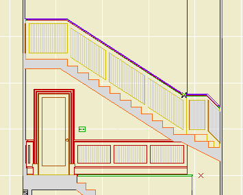
The height is the height of the vertical sides, not the overall height.
The slope can be set either by entering the angle or the rise and run. Note: Stair Stringer JAM8 knows its angle in degrees. You can copy it from the settings and paste it into the panel's settings.
It's one of those things that's easier to edit in a section window. Remember windows and doors can be stretched and copied in section.
It looks slightly different in plan from Trim Panel JM9. The handle lines point in the downward-sloping direction.
Location: 06 Wood & Plastic/Trim & Moulding
Identical to Trim Panel JM9 and Trim Panel Ceiling JM9, except it's a skylight. And since it's a skylight, it can only be rectangular.
(Q: Why don't you give the ceiling version a slope parameter, then we could subtract from roofs and have all the shapes? A: Good idea, but you can only subtract straight down. You would need to subtract in an angled direction. A wish.)
The 'height' is stretchable in 3D. The height is stretchable in plan too, though the plan view is foreshortened. Further, the plan image shows the shape at the bottom of the roof, what you'd want to see in the RCP. But the hole in the roof is displayed as seen from the top; they won't align, don't worry about it.
Location: 06 Wood & Plastic/Trim & Moulding
Identical to Trim Panel JM9, except it's an object instead of a window, and it lays flat.
It's for putting panels in slabs, for ceilings.
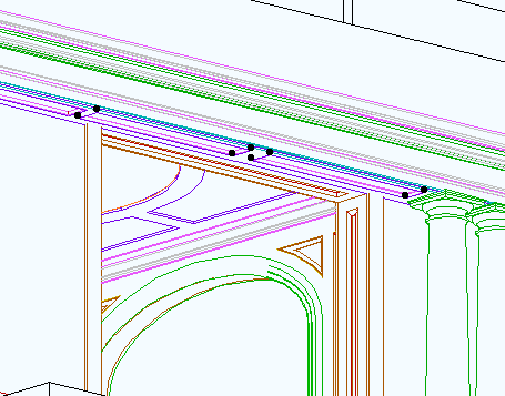
No, it can't actually cut the hole. You have to do that, using SEOs. Target: slab, operator: panel object. Subtract with downwards extrusion. (There is evidence of a SLABHOLE capability in AC, but it is not realized.)
You can choose to show it in the RCP by putting on the layer F Trim Crown.
The 'cut' shapes are editable in plan.
You can show a fill inside the plan polygon.
Location: 06 Wood & Plastic/Trim & Moulding
Actually a window. For placing panels in a thin wall, which would be the casing. Use a 1" thick wall for 5/4x, and 3/4" for 1x.
The object is based on Panel Hole JAM9. The difference is the addition of other shapes. This renders obsolete Panel Hole Int Trapezoid.
Each shape can point up or down (Orientation parameter). The available shapes are:
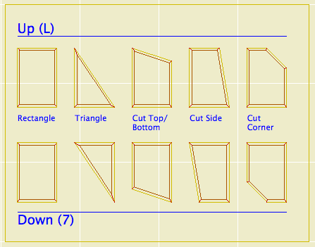
All these shapes are based on a right angle. If you need irregular triangles, let me know, I would probably do a separate object for those. I am working on an arbitrary-polygon drag-and-drop panel, but it isn't done.
You are encouraged to suggest other shapes. An octagon would be very simple if anyone needs it.
There is a selection of surround mouldings, including 'none'. The panel itself can be modeled or not, and if it is modeled it can have a thickness of zero (like a coat of paint). The panel can be raised or flat.
You can turn off the moulding and the panel and just have an empty opening.
If you choose any of the 'cut' shapes (Top/Bottom, Side, Corner), you can set the cut distance or the cut angle. The angle is useful when placing a panel under a stair or roof. The angles and cuts should intelligently when one or the other is changed.
You can choose to cut the actual hole with the object's pen or the wall's pen (Cut Pen parameter). Panels should have a weight of 2 (22, etc). For interior panels, you can make the wall this weight, and use the 'Wall' pen setting in the panel. On the exterior, the panel wall should be a 3 weight, and the hole should be cut with the object's pen, which should be a 2 weight.
In plan, the window has two red line 'handles' to make it easier to select. You can drag the window by these handles, but unfortunately you can't stretch.
At larger scales (3/4" and bigger), the moulding will show a wood fill in section. Otherwise, it will show the object's main fill. I'm working on getting the scale-sensitive fill thing in all the trim objects.
« Newer | All Entries | 1 | 2 | 3 | 4 | 5 | 6 | 7 | 8 | 9 | 10 | 11 | 12 | 13 | 14 | 15 | 16 | Older »