On Land

Environment Information
At Rill Architects we run ArchiCAD on macOS. If you work at Rill, this is your stuff. If you don't, but you work in ArchiCAD, you may find something interesting. Anybody else, I don't know.
RSS
Objects Archive

« Newer | All Entries | 1 | 2 | 3 | 4 | 5 | 6 | 7 | 8 | 9 | 10 | 11 | 12 | 13 | 14 | 15 | 16 | Older »

Location: 12 Furnishings / Casework

Another tweak to the blob. You can turn the Front Panel off. Why? So you can build the front of the cabinet out of a wall, and place the doors using 12 Furnishings / Casework / Cab Door Door JAM81. You would place that with the door tool, yes. (There's also Cab Door Object JAM81, the object tool implementation of the same thing.)

While I was in there I added a parameter for the box Stock Thickness. It defaults to 3/4". So the wall thickness should be 3/4" unless you change that parameter.

In plan, the front line is drawn at the front of the front, whether the object's panel is on or off. Tip: Use the front line as a guide to draw the wall.

Cabinet Axon
I know, I forgot the handles, sorry

Location: 06 Wood & Plastic/Trim & Moulding

The baseboard tool is for baseboards. That's pretty much it.

Feature Summary Baseboard profile, cap, shoe, and 'second' (lower) base; scale sensitive profiles and fills.

The baseboard tool is similar to the crown tool. The same shapes are available. (Pardon me if you find the term 'coffer' misplaced when considering base.) The miters and returns are the same. The scale sensitivity is the same, including the fills.

Here's the custom interface panel. Some of the options in the 'shape' area will change depending which shape is chosen.


All of the parts are optional except the base itself.

At building section scales, the shoe and cap are not modeled. The base will be shown at the height of the top of the cap.

New in 10 version: Slope.

Tip: Copy and paste the angle from the Stair Body object. The high end is the start end and the slope is down. The start end is represented in plan by the red diagonal line.

If the base slopes and meets other base pieces, it's going to need to miter in the other direction. For this we have Start Vert Cut and End Vert Cut. Level pieces can also be cut this way, since they might have to meet a sloped one.

Slope base edit
The vertical cuts are editable in 3D, but you will find it more practical to edit them in section/elevation.

Tip: First over extend the angles so they cross, then you can detect the point where they meet as an intersection.

You will usually need more height on a stair base than the level bases it meets.

Slope base edit
The sloped object length is directly editable, as is the slope angle itself using the middle 3D hotspot.

Baseboard elements should generally be placed on the layer F Trim Int Lo.

Swoop 10 Plan
Location: 13 Special Construction

All of Swoop JAM9a still in effect.

Added:

-- Optional Cover fill and all related parameters. You can allow the slope of the object to Distort the fill. No, the distortion doesn't vary as the slope changes. You can move the fill's origin using a hotspot; you have to select the object to see it. The hotspot.

With the cover fill on you should be able to show the swoop in roof plans. Turn the Back Lines off to help the object blend into the roof. (Use the A Roof2 layer in this case.)

-- Gable cuts at either end for fitting the object into a gable end. This is independent of the miter angles, and in fact you can't miter and gable-cut at the same time. (If you set gable cuts the miters turn themselves off.)

Crown 10 Sketch
Still rough
Location: Beta

Incoming update to the main crown object. It's pretty good now but I know there are some problems and there are probably some I don't know about until you find them.

Kindly have a look at this if you get a minute. That doesn't mean use it all over the place all of a sudden; just have a look at it. Remember this is an object you use dozens of times a day and it needs to work. If there's something that's been bugging you about the 9 version, check if it's fixed or remind me to fix it.

Feature-wise, the big change is that the rakes are handled as shapes within the Crown Tool. This object will supersede Rake JM9 and Rake Arc JM9. This is better because the rakes and crowns will have identical settings and options. These shapes should work the same as the current rake objects. I'll document them in full when the object is 'done'.

I also added some 'pieces'. Most important is the Soffit. You need the soffit to get the rake shape to subtract from the roof edge in case the cut is deeper than the mouldings themselves.

And there's Wall Backer 2, which is just an additional backer behind the wall backer.

And there's Crown Cap, a cap moulding directly below the crown moulding. You will almost never use this, but we need it on at least one project at the moment.

UPDATE:

Another shape: Arch. The end cuts are perpendicular. For an arched dormer: Place an arch crown on the front, and a straight crown object on each side. Switch on the returns on the front ends of the sides. Switch off end lines as needed.

Arch Crown

Another shape: J. Same as 'U' but you can stretch the third segment independently.

J Crown

Plus, secret surprise feature that only works in 11.

Thanks in advance for your help.

(1) A custom profile for modeling and (2) an object for annotation.

Profile:

Soffit profile
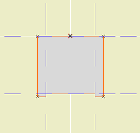
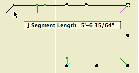
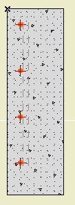
In the profile editor
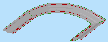
• The shape is that of two fascia boards with a reveal of 1/4" below the soffit board.

• The horizontal stretch extents are inside the fascia board reveals. This way, when you adjust the overall width the fascia thickness will be unchanged. Similarly, the vertical stretch extents go from the top to the underside of the soffit, leaving out the reveal.

The custom profile tech only allows you to stretch one dimension horizontally and one vertically. You can exempt parts of the profile from stretching, but you can't stretch them independently. If you want a different reveal depth or fascia thickness, you'll need another profile.

• Profiles can stretched bigger, but not smaller. (I call this a bug, but what do I know.) Any profile you intend to use with varying dimensions needs to match or be *smaller* than the smallest case you have.

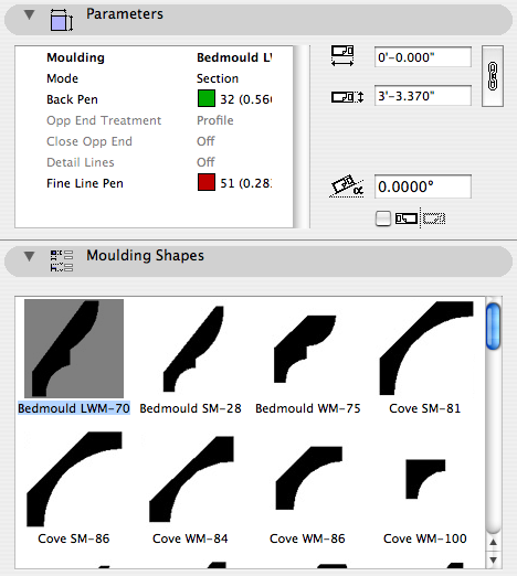
• The templates have two profiles, Coffer Beam and Coffer Beam Half. Both are 4" x 2" which should be small enough. The half version has the fascia on only one side and is meant to be placed along a wall.

Remember that profiles are attributes, so they're within the project file, so you can edit them without messing up anybody else. And: You can use Attribute Manager to bring profiles into the current project from the templates.

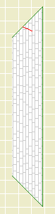
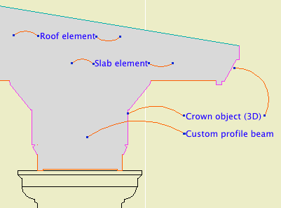
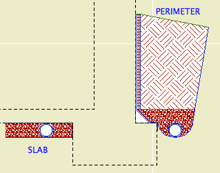
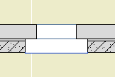
Here is a sample condition at 1/4" scale, no detail added:

1/4 scale soffit

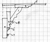
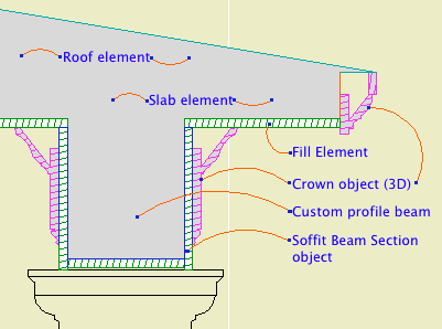
At higher scale, we need to add detail:

3/4 scale soffit

Object: Soffit Beam Section JM10

Location: 06 Wood & Plastic / 2D Wood

The object fits within the profile's perimeter.

Height and width of the object will match that of the beam itself.

• Parameters for Fascia thickness and reveal.
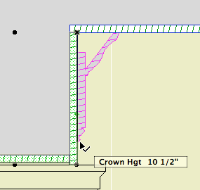
Crown Hgt sets the point at which the pen switches from the object's cut pen to the Separator Pen. In practice this height should meet the bottom of a crown object placed against the beam, which will maintain the heavy outline.

Crown height stretch

• The Half option uses one fascia board to work with the half version of the profile.

Commentary:

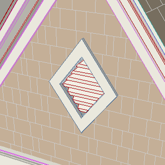
We build one model. We take views of the model and annotate them as needed. We will take views of the model at various scales. Scale is fundamental to architectural documentation: As we look closer, we see more.

Yet Archicad lacks any meaningful automatic scale sensitivity, except that written into objects by people who want it such as me.

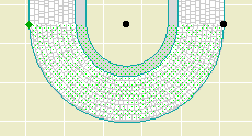
In this example, see how the crown objects draw themselves as empty blobby things at 1/4" scale, but they're detailed shapes with proper fills at higher scales. The roof, slab, and beam elements, not so much. (Archicad library objects, not so much either.)

Since we can't get conventional AC elements to detail themselves according to scale (yet, I hope I hope), we need to build a model that can accommodate the detail we need to add. This is the idea behind something like the Stud Wall Detail object. The wall is empty, and we place the object in the viewpoints that need it.

The soffit detail described here has always been tricky. If you approximate the beam with a rectangular model, it's difficult to manage the reveal without masking. It's easier to add 2D detail than to subtract modeling.

A custom profile allows us to handle the cased beam in the "Empty Fill +" fashion we are accustomed to with walls, roofs, and floor decks.

Rebar Section
Location: 05 Metals / 2D Steel

A 2D symbol to draw rebars in concrete structures.

Arrangement: Same as the Multiply command. Spread will place bars across the length of the object using the Spacing OC. Distribute will space the Quantity of bars evenly along the length.

You might use Distribute in a footing detail, where the spec would call for a number of bars, and Spread in a wall detail, where the spec calls for bars at a given spacing.

With the Spread arrangement, the end of the object is represented by a non-printing cross symbol.

Perpendicular Bars draws a pair of dashed lines behind the bar dots, representing the bars going the other way.

Coverage Hotspots places detectable points on the edge of the section dots at both ends. Use these spots to place the rebar object acurately and to dimension the coverage.

Graphic Crosses draws a cross through each bar to help with visibility.

Foundation Drains
Location: 07 Thermal & Moisture

A 2D symbol for foundation perimeter drains and underslab drains in wall sections. In Perimeter mode, it draws the drain tile (pipe), gravel, cant strip, membrane, drainage board, and backfilled earth. In Slab mode, it draws the drain tile and gravel.

Dimensions (Perimeter version):

Height parameter: From the top of the footing to the top of the masonry ledge or grade level, whichever is less. If there's no ledge, the height will go to the grade and no board extension (see below) is needed. If there is a ledge, the height goes there and the extension streches to meet the grade.

Footing Width: Width of the footing beyond the wall, typically 6".

Cant Width: Width of the cant strip, typically 4".

Drain Diameter: Obvious

Drain Board Thickness: Obvious

Membrane Thickness: Needs to be enough to get the membrane/drain board edge clear of the heavy contour line of the wall. This will depend on the scale and line weights, but 5/16" seems to be a minimum. Be sure to check the printed output, not just the true weight on the screen.

Board Extension: In the masonry ledge case, the height added to the top of the object to meet grade level.

The grade line and backfill angles are controlled by the hotspot at the top right corner (left if mirrored).

The gravel depth matches the cant strip height, which is driven by the cant width.

The membrane overlap on the footing matches the radius of the drain.

The gutter is 2.5 times the drain diameter.

Dimensions (Slab version):

The gravel depth is defined by the drain diameter. The length is set by the Length parameter.

There is also a Drain Only mode which draws only the drain. In this mode the Filter atop the pipe can be on or off.

Attributes:

The Fill Pen is used for all the fills. The Outline Pen is used for the interior lines and the non-cut edges. The Cut Pen is used for the edges along the wall. (This way, the wall contour won't appear 'thinned' by the object.) The Grade Pen is used for the top lines. The grade line is usually one click heavier than the typical cut line weight.

The fills should be clear enough. But. In developing this object I realized that the proper fill for backfill earth had somehow slipped out of the templates. It's back now, but you should make sure you have the fill when you use this object. Use Attribute Manager and do the following:

• Go to the fills tab.

• In the right panel, click open and navigate to the 'NewHome10.tpl' in the zTemplate folder.

• In the right panel, scroll down until you see fills number 102 and 103. Highlight both of them.

• Click 'Overwrite' (not 'Append') in the center, then Apply, and confirm the modification.

• Close up the Attribute Manager.

The fill you want is '*Earth Backfill'. BTW, undisturbed earth should use the fill '*Earth'.

Curved Roof Cut

Improvement on the AC9 version to interact with the Floor Plan Cut Plane.

Turn on the 'Use Cut Plane' option.

This isn't a FPCP-comprehensive solution as you'd see with a conventional roof. It's still up to you to put the object on the first 'visible' story and show it one story up. On the story above, the object is drawn complete, with no FPCP interaction. Further, I'm not checking if the object is entirely above the FPCP; that's up to you to figure out. If the object is entirely above the plane, then it should be cut n pasted to the next story up. (If it is above the plane, it will be drawn as if uncut.)

Rafter Ends
Rafter Ends
Location: 06 Wood & Plastic

Further improvement on this. The 9 library is clinging to life at this point.

More»

Diamond Vent
Location: 08a Windows / Vents

A diamond-shaped louvered gable vent.

It is designed with the assumption that will have the shape of the diamond follow the roof slope in most cases. Like many roof-oriented objects, you can choose the Roof Slope from a list or enter a custom value in Slope Angle. When you change either the height or width, the other dimension will adjust automatically to maintain the angle and thereby the proportions of the shape.

I think the rest of the parameters are self-explaining: Louver Thickness, Spacing, Angle, and Pen; Exterior and Interior Casing Width, Thickness, and Material.

The vent handles a masonry condition by setting itself into the wall by the sill dimension. (Use the 'second' Construction Method button.) The sill is drawn with the Masonry Sill Pen.

Vent MO in plan
Moulding settings
Location: 06 Wood & Plastic / Trim & Moulding

2D Moulding JAM9 is the current standard 2D moulding object. It is part of the whole moulding profile scheme, where I can add a new shape in one place and offer it for use in as many objects as we want. The Crown Tool, baseboard, rake, shed crown, door and window trim, etc., etc., are all hooked together. The 2D object offers all the shapes of all types.

I notice that a lot of people still use the individual shape objects in 06 Wood & Plastic / 2D Smoot. This doesn't hurt anything, but be advised that I don't use them and I don't maintain them, i.e., I don't make new ones. I can think of several reasons to use the old ones though:

• Habit.

• There's a shape in there that you can't find in 2D Moulding JAM9.

• You like seeing the shapes in the object browser.

The first one, you're on your own. The other two I believe I've covered with this revision.

I've gone through the old folder and incorporated all the shapes into 2D Moulding JAM9. I think. You'll let me know of course, just like you would if you needed a shape for the first time.

I made a graphical browser for the shapes.

I also reordered the list a bit. This is just a very cumbersome list. The current scheme is groups of:

• Crowns (including cove, rake, and bedmould)

• Casing (including fluting)

• Base (including cap and shoe)

• Panelmould (including nosing)

I hope it makes your shape choosing all that it should be.

Preview
Location: 01 General / 1 Graphic Symbols (The old one was in Drawing Tools.)

This is our 'stair helper'. As described here, I'm not a fan of all-in-one solutions for stairs or other complicated assemblies. I would rather build from discrete parts, each of which does its own job well. The main structure of a stair consists of slabs for landings and Stair Body objects for the flights. The railings and newels are separate.

The RiserMeter is one piece of the whole stair method complex. It performs several helpful tasks:

More»

« Newer | All Entries | 1 | 2 | 3 | 4 | 5 | 6 | 7 | 8 | 9 | 10 | 11 | 12 | 13 | 14 | 15 | 16 | Older »