Updated for Archicad 25.

All the common layouts (that we can think of) are blocked up in the project templates. These guidelines apply no matter when a layout is first needed.
Alphabetical by name of thing. Please suggest improvements and additions. Many things have changed, many have stayed the same. Layer theory hasn't changed much. Current as of Archicad 20, which prompted some layer changes.
Big table below the fold.
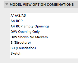
Beginning with Archicad 20, the fills division of Model View Options is obsolete and fills are handled by Graphic Overrides. This enables us to eliminate several combinations that were needed in Archicad 19.
Updated for Archicad 19.
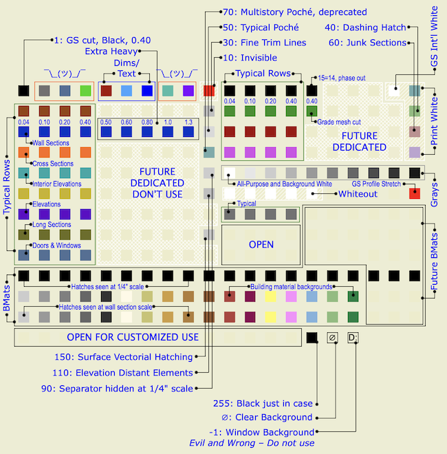
Pen sets let you change the appearance of output at the very last moment - when the drawing, based on the view, is headed out the door. The colors you see while working on the model can be completely different from the published output, and they should be.
Standard pens updated for Archicad 19.
The only substantive change since 2007 is that we've dropped pen 170 for structural posts on the story below. This was an ugly hack that's no longer needed since we can use Library Globals to control display of those elements.
That's a very small change, but I wanted it to be clear that these standards are still current. I updated the graphic. I have strong opinions about pen -1.
Sloppy modeling leads to sloppy documentation. That wall that's supposed to be 7'-0" long, but you built it 7'-0 5/64", so it dimensions at 7'-0 1/8", and the published output looks ridiculous.
Sloppy modeling doesn't clean up right in plan, section, elevation. (It looks fine in OpenGL with contours off. Great.) That means extraneous lines that either mislead the viewer or have to manually managed by you. Not everything cleans up, but everything that can, should. And sloppy modeling does not.
Once you have sloppy elements placed, you will likely refer to them to place other elements, and the slop spreads like a virus.
Sloppy modeling is not easier. This is how you model precisely:
• Use direct entry of distances. This means: Start placement, type 'R' (Hello world: Archicad default is 'D'), enter the distance and strike return.
• To place elements a set distance from a known point, move the origin (Opt+Shift) and use direct entry of X and Y by typing 'X' and 'Y'.
• If you are placing something 'roughly', it's still better to pick a number. Start the wall, e.g., and when it's 'about right', look at the R field (Distance in Tracker) and mentally round off the ugly number there. Then type 'R', enter your rounded distance, and strike return.
• Place the model with a sensible relationship to the global origin. A centerline, a corner, etc. You can reset the user origin to the global origin and 'feel around' with the cursor to see which end of Mr. 7'-0 5/64" is the bad end.
• If you're trying to center something, just center it. Draw any linear element from side to side, find the midpoint, and put something there. I would use a Center Line object because it is distinctive. Lesser but acceptable solutions include hotspots and non-printing lines. (Graphisoft wants you to use the new permanent guide lines, but I'm not a fan.) Whatever the thing, consider locking it. You can also use snap guides in AC19+ to find midpoints, or the old snap points constraint on the Control Box.
• Use a Center Point object to mark the center of curves, to make sure concentric elements are truly concentric. Show on all stories as needed. Lock it.
• Our plan-scale dimension standard is set to 1/8" precision. We only want to see output dimensions of 1/4" precision. (Unless there is an angle involved.) When you expect to see 7'-0" and see 7'-0 1/8" instead, that is your warning that something is off. Track down the 5/64" and fix it.
If any of these things is harder than clicking kinda wherever, I'm not seeing it.
Precise modeling is essential to Archicad success.
In the old days, things were different. How different depends on how old the days are. It's hard to anticipate every issue you might encounter in an old project. The first question is, what do you need from the project? Do you need drawings, a detail, or are we actually resuming work on the project?
Leads and pending projects should be placed in 1 Projects / zPending.
These are projects which have no modeling or design data with them. They might be just a proposal.
When a pending project actually begins, create the project folder as normal. Drag any documents in the pending folder to the new project folder. The proposal belongs in '3 Contract & Correspondence / Proposal'. Trash the project's 'pending' folder.
If a project does not go forward, we will move it to 5 Past Projects as part of our quarterly project cleanup.
When dimensioning, strive for stunning, perfect, complete, beautiful clarity. I'm serious.
This is everything I can think of about libraries management. There have been a lot of changes over the years.